
More Related Content
What's hot
What's hot (20)
Similar to Handouts dc machines
Similar to Handouts dc machines (20)
Recently uploaded
Recently uploaded (20)
Handouts dc machines
- 1. DC MACHINES A DC Machine is an electro-mechanical energy conversion device. There are two types of DC machines; one is DC generator, and another one is known as DC motor. A DC generator converts mechanical power (ωT) into DC electrical power (EI), whereas, a DC motor converts d.c electrical power into mechanical power. The AC motor is invariably applied in the industry for conversion of electrical power into mechanical power, but at the places where the wide range of speeds and good speed regulation is required, like in electric traction system, a DC motor is used. The construction of dc motor and generator is nearly same. The generator is employed in a very protected way. Hence there is open construction type. But the motor is used in the location where they are exposed to dust and moisture, and hence it requires enclosures for example dirt proof, fire proof, etc. according to requirement. Although the battery is an important source of DC electric power, it can only supply limited power to any machines. There are some applications where large quantities of DC power are required, such as electroplating, electrolysis, etc. Hence, at such places, DC generators are used to deliver power. BasicStructureofElectricalMachines The rotating electrical or DC machine has mainly two parts; one is Stator, and another one is Rotor. The stator and rotor are separated from each other by an air gap. The stator is the outer frame of the machine and is immovable. The rotor is free to move and is the inner part of the machine. Both the stator and the rotor are made of ferromagnetic materials. Slots are cut on the inner periphery of the stator and the outer periphery of the rotor. Conductors are placed in the slots of the stator or rotor. They are interconnected to form windings. The windings in which voltage is induced is called the Armature windings. The winding through which a current is passed to produce the main flux is called the Field windings. To provide main flux in some of the machine permanent magnets is also used. Construction of a DC machine: Note:A DC generator can be used as a DC motor without any constructional changes and vice versa is also possible. Thus, a DC generator or a DC motor can be broadly termed as a DC machine. These basic constructional details are also valid for the construction of a DC motor.
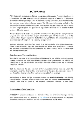
- 2. The above figure shows constructional details of a simple 4-pole DC machine. A DC machine consists of two basic parts; stator and rotor. Basic constructional parts of a DC machine are described below. 1. Yoke: The outer frame of a dc machine is called as yoke. It is made up of cast iron or steel. It not only provides mechanical strength to the whole assembly but also carries the magnetic flux produced by the field winding. 2. Poles and pole shoes: Poles are joined to the yoke with the help of bolts or welding. They carry field winding and pole shoes are fastened to them. Pole shoes serve two purposes; (i) they support field coils and (ii) spread out the flux in air gap uniformly. 3. Field winding: They are usually made of copper. Field coils are former wound and placed on each pole and are connected in series. They are wound in such a way that, when energized, they form alternate North and South poles. 4. Armature core: Armature core is the rotor of a dc machine. It is cylindrical in shape with slots to carry armature winding. The armature is built up of thin laminated circular steel disks for reducing eddy current losses. It may be provided with air ducts for the axial air flow for cooling purposes. Armature is keyed to the shaft. 5. Armature winding: It is usually a former wound copper coil which rests in armature slots. The armature conductors are insulated from each other and also from the armature core. Armature winding can be wound by one of the two methods; lap winding or wave winding. Double layer lap or wave windings are generally used. A double layer winding means that each armature slot will carry two different coils. 6. Commutator and brushes: Physical connection to the armature winding is made through a commutator-brush arrangement. The function of a commutator, in a dc
- 3. generator, is to collect the current generated in armature conductors. Whereas, in case of a dc motor, commutator helps in providing current to the armature conductors. A commutator consists of a set of copper segments which are insulated from each other. The number of segments is equal to the number of armature coils. Each segment is connected to an armature coil and the commutator is keyed to the shaft. Brushes are usually made from carbon or graphite. They rest on commutator segments and slide on the segments when the commutator rotates keeping the physical contact to collect or supply the current. Working principle of a DC generator: According to Faraday’s laws of electromagnetic induction, whenever a conductor is placed in a varying magnetic field (OR a conductor is moved in a magnetic field), an emf (electromotive force) gets induced in the conductor. The magnitude of induced emf can be calculated from the emf equation of dc generator. If the conductor is provided with a closed path, the induced current will circulate within the path. In a DC generator, field coils produce an electromagnetic field and the armature conductors are rotated into the field. Thus, an electromagnetically induced emf is generated in the armature conductors. The direction of induced current is given by Fleming’s right hand rule. Need of a Split ring commutator: According to Fleming’s right hand rule, the direction of induced current changes whenever the direction of motion of the conductor changes. Let’s consider an armature rotating clockwise and a conductor at the left is moving upward. When the armature completes a half rotation, the direction of motion of that particular conductor will be reversed to downward. Hence, the direction of current in every armature conductor will be alternating. If you look at the above figure, you will know how the direction of the induced current is alternating in an armature conductor. But with a split ring commutator, connections of the
- 4. armature conductors also gets reversed when the current reversal occurs. And therefore, we get unidirectional current at the terminals. EquivalentCircuitofaDCMachineArmature The armature of a DC generator can be represented by an equivalent electrical circuit. It can be represented by three series-connected elements E, Ra and Vb. The equivalent circuit of the armature of a DC generator is shown below in the figure. The equivalent circuit of the armature of a DC Motor is shown below in the figure.
- 5. The element E in the equivalent circuit diagrams is the generated voltage, Ra is the armature resistance, and Vb is the brush contact voltage drop. Types of Armature Winding Generally, the armature winding in dc machine is wound by using two techniques and these are also known as types of an armature winding such as Lap Winding and Wave Winding. a). Lap Winding In this type of winding, the connection of the conductors is done in such a way that their parallel poles & lanes are similar. The last part of every armature coil can be connected toward the nearby section on the commutator. The digit of brushes in this winding can be similar toward the digit of parallel lanes, & these brushes are separated evenly into positive as well as negative polarity winding. The applications of lap winding mainly include high- current, low voltage machines. lap windings are classified into three types which include the following. Lap Winding • Simplex Type Lap Winding • Duplex Type Lap Winding • Triplex Type Lap Winding 1). Simplex Type Lap Winding In this kind of winding, the ending of one coil is connected to the commutator section as well as the beginning end of the secondary coil can be arranged under a similar pole, and also the digit of parallel lanes is equal to the digit of poles of the windings.
- 6. 2). Duplex Type Lap Winding In this type of winding, the digit of parallel lanes among the pole is double the digit of poles. The applications of lap winding mainly involve in huge current applications. Such kind of winding is obtained by arranging the two same windings on the similar armature as well as linking the even number commutator bars toward the primary winding & the off number to the secondary winding. 3). Triplex Type Lap Winding In this type of winding, the windings are associated with the 1/3rd of the bars of the commutator. This lap winding has several lanes as well as therefore the applications of triplex type lap winding mainly involve in huge current applications. the main drawback of this winding is that it uses several conductors which will enhance the winding cost. b).Wave Winding In this kind of wave winding, there are only two parallel lanes among the positive as well as negative brushes. The final end of the first armature coil is linked with the beginning end of the second armature coil commutator segment at some distance. In this kind of winding, the conductors are associated with the two parallel lanes of the machine poles. The digit of parallel ports is equivalent to the digit of brushes. This kind of winding is applicable for low-current, high-voltage machines. Once it passing one round, then the armature winding drops into a slot toward the left side of its beginning point. So this type of winding is named as retrogressive windings. Similarly, once the windings of an armature drop on one slot toward the right then it is named as progressive winding. Suppose the two winding layers & that the AB conductor must be at the higher layer semi of the slot on the right or left. Assume that the YF and YB are front and back pitches. The
- 7. amounts of these pitches are nearly the same to the winding pole pitch. The the following equation gives the winding average pitch. The following equation provides the winding’s standard pitch. YA =YB + YF/2 If the whole no. of the conductor is ZA, then the normal pitch can be defined by the following equation YA =Z+2/p or YA =Z-2/p In the above equation, the number of poles can be denoted with ‘P’, and it is always even, so Z is always measured like an even digit Z = PYA ± 2. Here, both the signs like + and – are used for progressive winding as well as retrogressive windings. EmfEquationofaDCGenerator As the armature rotates, a voltage is generated in its coils. In the case of a generator, the emf of rotation is called the Generated emf or Armature emf and is denoted as Er = Eg. In the case of a motor, the emf of rotation is known as Back emf or Counter emf and represented as Er = Eb. The expression for emf is same for both the operations. I.e., for Generator as well as for Motor. Let, • P – Number of poles of the machine • ϕ – Flux per pole in Weber. • Z – Total number of armature conductors. • N – Speed of armature in revolution per minute (r.p.m). • A – Number of parallel paths in the armature winding. In one revolution of the armature, the flux cut by one conductor is given as Time taken to complete one revolution is given as
- 8. Therefore, the average induced e.m.f in one conductor will be Putting the value of (t) from Equation (2) in the equation (3) we will get The number of conductors connected in series in each parallel path = Z/A. Therefore, the average induced e.m.f across each parallel path or the armature terminals is given by the equation shown below. Where n is the speed in revolution per second (r.p.s) and given as For a given machine, the number of poles and the number of conductors per parallel path (Z/A) are constant. Hence, the equation (5) can be written as Where, K is a constant and given as
- 9. Thus, it is clear that the induced emf is directly proportional to the speed and flux per pole. The polarity of induced emf depends upon the direction of the magnetic field and the direction of rotation. If either of the two is reverse the polarity changes, but if two are reversed the polarity remains unchanged. If the machine DC Machine is working as a Generator, the induced emf is given by the equation shown below. Where Eg is the Generated Emf If the machine DC Machine is working as a Motor, the induced emf is given by the equation shown below. In a motor, the induced emf is called Back Emf (Eb) because it acts opposite to the supply voltage. Armature Reaction in DC machines In a DC machine, two kinds of magnetic fluxes are present; 'armature flux' and 'main field flux'. The effect of armature flux on the main field flux is called as armature reaction. MNA and GNA EMF is induced in the armature conductors when they cut the magnetic field lines. There is an axis (or, you may say, a plane) along which armature conductors move parallel to the flux lines and, hence, they do not cut the flux lines while on that plane. MNA (Magnetic Neutral Axis) may be defined as the axis along which no emf is generated in the armature conductors as they move parallel to the flux lines. Brushes are always placed along the MNA because reversal of current in the armature conductors takes place along this axis.
- 10. GNA (Geometrical Neutral Axis) may be defined as the axis which is perpendicular to the stator field axis. The effect of armature reaction is well illustrated in the figure below. Consider, no current is flowing in the armature conductors and only the field winding is energized (as shown in the first figure of the above image). In this case, magnetic flux lines of the field poles are uniform and symmetrical to the polar axis. The 'Magnetic Neutral Axis' (M.N.A.) coincides with the 'Geometric Neutral Axis' (G.N.A.). The second figure in the above image shows armature flux lines due to the armature current. Field poles are de-energised. Now, when a DC machine is running, both the fluxes (flux due to the armature conductors and flux due to the field winding) will be present at a time. The armature flux superimposes with the main field flux and, hence, disturbs the main field flux (as shown in third figure the of above image). This effect is called as armature reaction in DC machines.
- 11. The adverse effects of armature reaction: 1. Armature reaction weakens the main flux. In case of a dc generator, weakening of the main flux reduces the generated voltage. 2. Armature reaction distorts the main flux, hence the position of M.N.A. gets shifted (M.N.A. is perpendicular to the flux lines of main field flux). Brushes should be placed on the M.N.A., otherwise, it will lead to sparking at the surface of brushes. So, due to armature reaction, it is hard to determine the exact position of the MNA For a loaded dc generator, MNA will be shifted in the direction of the rotation. On the other hand, for a loaded dc motor, MNA will be shifted in the direction opposite to that of the rotation. To reduce armature reaction Compensating winding: Now we know that the armature reaction is due to the presence of armature flux. Armature flux is produced due to the current flowing in armature conductors. Now, if we place another winding in close proximity of the armature winding and if it carries the same current but in the opposite direction as that of the armature current, then this will nullify the armature field. Such an additional winding is called as compensating winding and it is placed on the pole faces. Compensating winding is connected in series with the armature winding in such a way that it carries the current in opposite direction. Interpoles: Interpoles are the small auxiliary poles placed between the main field poles. Winding on the interpoles is connected in series with the armature. Each interpole is wound in such a way that its magnetic polarity is same as that of the main pole ahead of it. Interpoles nullify the quadrature axis armature flux. CommutationinDCMachine The currents induced in the armature conductors of a DC generator are alternating in nature. The change from a generated alternating current to the direct current applied involves the process of Commutation. When the conductors of the armature are under the north pole, the current which is induced flows in one direction The current flows in the opposite direction when they are under south pole. As the conductor passes through the influence of the north pole and enters the south pole, the current in them is reversed. The reversal of current take place along the MNA or brush
- 12. axis. When the brush span has two commutator segments, the winding element connected to those segments is short-circuited. The term Commutation means the change that takes place in a winding element during the period of a short circuit by a brush. Let us understand Commutation more clearly by considering a simple ring windings shown below in Figure A. In the position shown in Figure A, the current I flowing towards the brush from the left-hand side passes round the coil in a clockwise direction. Now consider the other figure B shown below.
- 13. In the above figure, the position of the coil shows that the same amount of current is carried by all the coils, and the direction of the current is also similar, but the coil is too short- circuited by the brush. In the Figure C shown below the brush makes contact with bars a and b, thereby short- circuiting coil 1. The current is still I from the left-hand side and I from the right-hand side. It is seen that these two currents can reach the brush without passing through coil 1. In the figure D shown below, the bar (b) has just left the brush, and the short circuit of coil one has ended. It is now necessary for the current I reaching the brush from the right-hand side in the anticlockwise direction.
- 14. From all the above discussion, it is seen that during the period of the short circuit of an armature coil by a brush the current in the coil must be reversed and also brought up to its full value in the reversed direction. The time of the short circuit is called the period of commutation. The figure shown below shows how the current in the short-circuited coil varies during the brief interval of the short circuit. Curve b shows that the current changes from +I to –I linearly in the commutation period. Such a commutation is called Ideal Commutation or Straight-line Commutation. If the current through the coil 1 has not reached its full value in the position in figure D, then, since the coil 2 carrying full current, the difference between the currents through elements 2 and 1 has to jump from commutator bar to the brush in the form of a spark. Thus, the cause of sparking at the commutator is the failure of the current in the short- circuited elements to reach the full value in the reverse direction by the end of the short circuit.This is known as under commutation or delayed commutation. The curve of current against time in such a case is shown in figure E by the curve A. In ideal commutation curve B, the current of the commutating coils changes linearly from +I to –I during the commutation period.
- 15. In actual practice, the current in the short-circuited coil after commutation period does not reach its full value. This is due to the fact that the short-circuited coil offers self-inductance in addition to the resistance. The rate of change of current is so high that the self- inductance of the coil sets up a back EMF, which opposes the reversal. Since the current in the coil has to change from +I to –I, the total change is 2I. If tc is the time of short circuit and L is the inductance of the coil (= self-inductance of the short- circuited coil + mutual inductances of the neighbouring coils), then the average value of the self-induced voltage is This is called the reactance voltage. The large voltage appearing between commutator segments to which the coil is connected causes sparking at the brushes of the machine. The sparking of the commutator is much harmful, and it will damage both commutator surface and brushes. Its effect is cumulative which may lead to a short circuit of the machine with an arc round the commutator from brush to brush. MethodsofImprovingCommutation There are three main methods of Improving Commutation or obtaining sparkles Commutation is Resistance and Voltage Commutation and Compensating Winding. Further, the voltage commutation consists of another two methods which are used to produce the injected voltage, named as Commutating poles or Interpoles and Brush Shift.
- 16. Resistance Commutation The Resistance Commutation method uses Carbon brushes for improving commutation. The use of Carbon brushes makes the contact resistance between commutator segments and brushes high. This high contact resistance has the tendency to force the current in the short- circuited coil to change according to the commutation requirements. Voltage Commutation In the Voltage Commutation method, the arrangement is made to induce a voltage in the coil undergoing the commutation process, which will neutralize the reactance voltage. This injected voltage is in opposition to the reactance voltage. If the value of the injected voltage is made equal to the reactance voltage, there will be a quick reversal of current in the short- circuited coil and as a result, there will be sparkles Commutation. The two methods used to produce the injected voltage in opposition to the reactance voltage are as follows. 1.Brush Shift The effect of armature reaction is to shift the magnetic neutral axis (MNA) in the direction of rotation for the generator and against the direction of rotation for the motor. Armature reaction establishes a flux in the neutral zone. A small voltage is induced in the commutating coil since it is cutting the flux. 2.Commutating Poles or Interpoles Interpoles are narrow poles placed in between the main poles and are attached to the stator Interpoles are also called commutating poles or Campoles. The interpoles windings are connected in series with the armature because the interpoles must produce fluxes that are directly proportional to the armature current. The armature and the interpoles mmfs are affected simultaneously by the same armature current. Consequently, the armature flux in the commutating zone, which tends to shift the magnetic neutral axis, is neutralized by an appropriate component of interpole flux. The interpoles must induce a voltage in the conductors undergoing commutation that is opposite to the voltage caused by the neutral plane shift and reactance voltage. In case of a generator: The neutral plane shifts are in the direction of rotation. Thus, the conductor undergoing the commutation, the polarity of the interpole must be the same i.e. similar to the next main pole in the direction of rotation. To oppose this voltage, the interpoles must have the opposite flux, which is the flux of the main pole ahead according to the direction of rotation. In case of a motor:
- 17. For a motor, the neutral plane shifts opposite to the direction of rotation, and the conductors undergoing commutation have the same flux as the main pole. For opposing this voltage, the interpole must have the same polarity as the previous main pole. The polarity of an interpole and main pole is opposite in the direction of rotation. The polarity of interpoles is shown in the figure below. The Interpoles serve only to provide sufficient flux to assure good commutation. They do not overcome the distortion of the flux resulting from cross-magnetizing mmf of the armature. During severe overloads or rapidly changing loads, the voltage between adjacent commutator segments may become very high. This ionizes the air around the commutator to the extent that it becomes sufficiently conductive. An arc is established from brush to brush. This phenomenon is known as Flashover. This arc is sufficiently hot to melt the commutator segments. It should be extinguished quickly. To prevent flashover, compensating windings are used. Compensating Windings The most efficient method of eliminating the problem of armature reaction and flashover by balancing the armature mmf is the compensating windings. The windings are placed in the slots provided in pole faces parallel to the rotor conductors. These windings are connected in series with the armature windings. The direction of currents in the compensating winding must be opposite to that in the armature winding just below the pole faces. Thus, compensating winding produces mmf that is equal and opposite to the armature MMF. The compensating winding demagnetizes
- 18. or neutralizes the armature flux produced by the armature conductors. The flux per pole is then undisturbed by the armature flux regardless of the load conditions. The major drawback with the compensating windings is that they are very costly. The primary use of the compensating winding is in particular cases, as given below • In large machine subject to heavy overloads or plugging. • In small motors subject to sudden reversal and high acceleration. TypesofDCGenerator–SeparatelyExcitedandSelfExcited The DC generator converts the electrical power into electrical power. The magnetic flux in a DC machine is produced by the field coils carrying current. The circulating current in the field windings produces a magnetic flux, and the phenomenon is known as Excitation. DC Generator is classified according to the methods of their field excitation. By excitation, the DC Generators are classified as Separately excited DC Generators and Self- excited DC Generators. There is also Permanent magnet type DC generators. The self- excited DC Generators are further classified as Shunt wound DC generators; Series wound DC generators and Compound wound DC generators. The Compound Wound DC generators are further divided as long shunt wound DC generators, and short shunt wound DC generators. The field pole of the DC generator are stationary, and the armature conductor rotates. The voltage generated in the armature conductor is of alternating nature, and this voltage is converted into the direct voltage at the brushes with the help of the commutator. Permanent Magnet type DC Generator In this type of DC generator, there is no field winding is placed around the poles. The field produced by the poles of these machines remains constant. Although these machines are very compact but are used only in small sizes like dynamos in motorcycles, etc. The main disadvantage of these machines is that the flux produced by the magnets deteriorates with the passage of time which changes the characteristics of the machine. Separately Excited DC Generator A DC generators whose field winding or coil is energised by a separate or external DC source is called a separately excited DC Generator. The flux produced by the poles depends upon the field current with the unsaturated region of magnetic material of the poles. i.e. flux is directly proportional to the field current. But in the saturated region, the flux remains constant. Self excited: In this type, field coils are energized from the current produced by the generator itself. Initial emf generation is due to residual magnetism in field poles. The generated emf causes a part of current to flow in the field coils, thus strengthening the field
- 19. flux and thereby increasing emf generation. Self excited dc generators can further be divided into three types - (a) Series wound - field winding in series with armature winding (b) Shunt wound - field winding in parallel with armature winding (c) Compound wound - combination of series and shunt winding
- 20. WorkingPrincipleofaDCMotor The DC motor is the device which converts the direct current into the mechanical work. It works on the principle of Lorentz Law, which states that “the current carrying conductor placed in a magnetic and electric field experience a force”. And that force is called the Lorentz force. The Fleming left-hand rule gives the direction of the force. Fleming Left Hand Rule If the thumb, middle finger and the index finger of the left hand are displaced from each other by an angle of 90°, the middle finger represents the direction of the magnetic field. The index finger represents the direction of the current, and the thumb shows the direction of forces acting on the conductor. The formula calculates the magnitude of the force, BackEMFinDCMotor When the current carrying conductor placed in a magnetic field, the torque induces on the conductor. The torque rotates the conductor which cuts the flux of the magnetic field. According to the Electromagnetic Induction Phenomenon “when the conductor cuts the
- 21. magnetic field, EMF induces in the conductor”. The Fleming right-hand rule determines the direction of the induced EMF. The magnitude of the back emf is given by the same expression shown below. Where Eb is the induced emf of the motor known as Back EMF, A is the number of parallel paths through the armature between the brushes of opposite polarity. P is the number of poles, N is the speed, Z is the total number of conductors in the armature and ϕ is the useful flux per pole. A simple conventional circuit diagram of the machine working as a motor is shown in the diagram below. In this case, the magnitude of the back emf is always less than the applied voltage. The difference between the two is nearly equal when the motor runs under normal conditions. The current induces on the motor because of the main supply. The relation between the main supply, back emf and armature current is given as Eb = V – IaRa.
- 22. Advantages of Back Emf in DC Motor 1. The back emf opposes the supply voltage. The supply voltage induces the current in the coil which rotates the armature. The electrical work required by the motor for causing the current against the back emf is converted into the mechanical energy. And that energy is induced in the armature of the motor. Thus, we can say that energy conversion in DC motor is possible only because of the back emf. The mechanical energy induced in the motor is the product of the back emf and the armature current, i.e., EbIa. 2. The back emf makes the DC motor self-regulating machine, i.e., the back emf develops the armature current according to the need of the motor. The armature current of the motor is calculated as TorqueEquationofaDCMotor When a DC machine is loaded either as a motor or as a generator, the rotor conductors carry current. These conductors lie in the magnetic field of the air gap. Thus, each conductor experiences a force. The conductors lie near the surface of the rotor at a common radius from its centre. Hence, a torque is produced around the circumference of the rotor, and the rotor starts rotating. When the machine operates as a generator at a constant speed, this torque is equal and opposite to that provided by the prime mover. When the machine is operating as a motor, the torque is transferred to the shaft of the rotor and drives the mechanical load. The expression is same for the generator and motor. When the current carrying current is placed in the magnetic field, a force is exerted or it which exerts turning moment or torque F x r. This torque is produced due to the electromagnetic effect, hence is called Electromagnetic torque. The torque which is produced in the armature is not fully used at the shaft for doing the useful work. Some part of it where lost due to mechanical losses. The torque which is used for doing useful work in known as the shaft torque. Since, Multiplying the equation (1) by Ia we get
- 23. Where, VIa is the electrical power input to the armature. I2aRa is the copper loss in the armature. We know that, Total electrical power supplied to the armature = Mechanical power developed by the armature + losses due to armature resistance Now, the mechanical power developed by the armature is Pm. Also, the mechanical power rotating armature can be given regarding torque T and speed n. Where n is in revolution per seconds (rps) and T is in Newton-Meter. Hence, But, Where N is the speed in revolution per minute (rpm) and
- 24. Where, n is the speed in (rps). Therefore, So, the torque equation is given as For a particular DC Motor, the number of poles (P) and the number of conductors per parallel path (Z/A) are constant. Where, Thus, from the above equation (5) it is clear that the torque produced in the armature is directly proportional to the flux per pole and the armature current. Moreover, the direction of electromagnetic torque developed in the armature depends upon the current in armature conductors. If either of the two is reversed the direction of torque produced is reversed and hence the direction of rotation. But when both are reversed, and direction of torque does not change.
- 25. ElectricalBrakingofDCMotor Electrical Braking is usually employed in applications to stop a unit driven by motors in an exact position or to have the speed of the driven unit suitably controlled during its deceleration. Electrical braking is used in applications where frequent, quick, accurate or emergency stops are required. Electrical Braking allows smooth stops without any inconvenience to passengers. Whenaloadedhoistislowered,electricbrakingkeepsthespeedwithinsafelimits.Otherwise,themachine ordrivespeedwillreachthedangerousvalues.When atraingoesdownasteep gradient,electricbrakingis employedtoholdthetrainspeedwithintheprescribedsafelimits.ElectricalBrakingismorecommonlyused whereactiveloadsareapplicable.Inspiteofelectricbraking,thebrakingforcecanalsobeobtainedbyusing mechanicalbrakes. DisadvantagesofMechanicalBraking ThemaindisadvantagesoftheMechanicalBrakingareasfollows:- • Itrequiresfrequentmaintenanceandreplacementofbrakeshoes. • Brakingpoweriswastedintheformofheat. Inspiteofhavingsomedisadvantagesofmechanicalbraking,itisalsousedalongwiththeelectricbrakingto ensurereliableoperationofthedrive.Itisalsousedtoholdthedriveatthestandstillbecausemanybraking methodsdonotproducetorqueatstandstillcondition. TypesofElectricalBraking There are three types of Electric Braking in a DC motor. They are Regenerative Braking, Dynamic or RheostaticBrakingandPluggingorReverseCurrentBraking RegenerativeBraking In Regenerative Braking, the power or energy of the driven machinery which is in kinetic form is returned back to the power supply mains. This type of braking is possible when the driven load or machinery forces the motor to run at a speed higher than no load speed with a constant excitation. Under this condition, the back emf Eb of the motor is greater than the supply voltage V, which reverses the direction of motor armature current. The machine now begins to
- 26. operate as a generator and the energy generated is supplied to the source. Regenerative braking can also be performed at very low speeds if the motor is connected as a separately excited generator. The excitation of the motor is increased as the speed is reduced so that the two equations shown below are satisfied. The motor does not enter into saturation on increasing excitation. Regenerative braking is possible with shunt and separately excited motors. In compound motors, braking is possible only with weak series compounding. Applications of Regenerative Braking •Regenerative braking is used especially where frequent braking and slowing of drives is required. •It is most useful in holding a descending load of high potential energy at a constant speed. •Regenerative braking is used to control the speed of motors driving loads such as in electric locomotives, elevators, cranes and hoists. •Regenerative braking cannot be used for stopping the motor. It is used for controlling the speed above the no-load speed of the motor driving. The necessary condition for regeneration is that the back EMF Eb should be greater than the supply voltage so that the armature current is reversed and the mode of operation changes from motoring to generating. Regenerative Braking in DC Shunt Motors Under normal operating conditions the armature current is given by the equation shown below When the load is lowered by a crane, hoist or lift causes the motor speed to be greater than the no-load speed. The back EMF becomes greater than the supply voltage. Consequently, armature current Ia becomes negative. The machines now begin to operate as a generator. Regenerative Braking in DC Series Motors
- 27. In case of DC Series Motor an increase in speed is followed by a decrease in the armature current and field flux. The back EMF Eb cannot be greater than the supply voltage. Regeneration is possible in DC Series Motor since the field current cannot be made greater than the armature current. Regeneration is required where DC Series Motor is used extensively such as in traction, elevator hoists etc. For example – In an Electro-locomotive moving down the gradient, a constant speed may be necessary. In hoist drives the speed is to be limited whenever it becomes dangerously high. One commonly used method of regenerative braking of DC Series Motor is to connect it as a shunt motor. Since the resistance of the field winding is low, a series resistance is connected in the field circuit to limit the current within the safe value. PluggingorReverseCurrentBraking In Plugging or Reverse Current Braking the armature terminals or the supply polarity of a separately excited or shunt motor when running are reversed. Therefore, in Plugging the supply voltage V and the induced voltage Eb which is also called back EMF will act in the same direction. Thus, during plugging the effective voltage across the armature will be (V + Eb) which is almost twice the supply voltage. The armature current is reversed, and a high braking torque is produced. An external current limiting resistor is connected in series with the armature to limit the armature current to a safe value. The connection diagram of DC separately excited motor and its characteristics is shown in the figure below. Where, • V is the supply voltage • Rb is the external resistance
- 28. • Ia is the armature current • If is the field current. Similarly, the connection diagram and the characteristic of the series motor in plugging mode is shown in the figure below. For braking, a series motor either the armature terminals or field terminals are reversed. But both armature and field terminals are not reversed together. Reversing of both the terminals will give only normal working operation. At the zero speed, the braking torque is not zero. The motor must be disconnected from the supply at or near zero speed when the motor is used for stopping a load. If the motor is not disconnected from the supply mains, the motor will speed up in the reverse direction. For disconnecting the supply centrifugal switches are used. The method of braking, known as Plugging or Reverse Current Braking is a highly insufficient method because, in addition to the power supplied by the load, power supplied by the source is also wasted in resistance. Applications of Plugging The Plugging is commonly used for the following purposes listed below. • In controlling elevators • Rolling Mills • Printing Presses • Machine tools, etc. DynamicBrakingorRheostaticBrakingofDCMotor
- 29. In Dynamic Braking, a braking resistor Rb is connected across the armature as soon as the DC motor is disconnected from the supply mains. The motor now works as a generator, producing the braking torque.For the braking operation in Dynamic Braking, the motor is connected in two ways. Firstly the separately excited or shunt motor can be connected either as a separately excited generator, where the flux is kept constant. The second way is that it can be connected to a self-excited shunt generator, with the field winding in parallel with the armature. The connection diagram of Dynamic Braking of separately excited DC motor is shown below. When the machine works in the motoring mode. The connection diagram is shown below when braking with separate excitation is done.
- 30. The connection diagram is shown below when braking with self-excitation is performed. This method is also known as Rheostatic Braking because an external braking resistance Rb is connected across the armature terminals for electric braking. During an electric braking, the kinetic energy stored in the rotating parts of the machine and the connected load is converted into electric energy, when the motor is working as a generator. The energy is dissipated as heat in the braking resistance Rb and armature circuit resistance Ra. The connection diagram of Dynamic Braking of DC Shunt Motor is shown below.
- 31. When the machine is working in the motoring mode. The connection diagram of shunt motor Braking with self and separate excitation is shown in the figure below. For Dynamic Braking, the series motor is disconnected from the supply. A variable resistance Rb as shown in the figure below is connected in series, and the connections of the field windings are reversed.
- 32. The field connections are reversed so that the current through the field winding flows in the same direction as before i.e. from S1 to S2 so that the back EMF produces the residual flux. The machine now starts working as a self-excited series generator. In self-excitation, the braking operation is slow. Hence, when a quick braking is required, the machine is
- 33. connected in self-excitation mode. A suitable resistance is connected in series with the field to limit the current to a safe value. The Dynamic or Rheostatic Braking is an insufficient method of braking because all the energy which is generated is dissipated in the form of heat in the resistance. Speed Regulation of DC Motor Definition: The speed regulation of a DC Motor is defined as the change in speed from no load to full load. It is expressed as a fraction or a percentage of the full load speed. Per unit speed regulation can also be defined as the ratio of the difference between no load to full load with respect to the full load. It is given by the equation shown below Where, • Nnlisthenoloadspeed • Nflisthefullloadspeed Amotorwhichhasnearly,aconstantspeedorthedifferencebetweennoloadandfullloadisverylessissaid tohaveagoodspeedregulation. SpeedControlofDCMotor: The dc motor converts the mechanical power into dc electrical power. One of the most important features of the dc motor is that their speed can easily be control according to the requirement by using simple methods. Such type of control is impossible in an AC motor. The concept of the speed regulation is different from the speed control. In speed regulation, the speed of the motor changes naturally whereas in dc motor the speed of the motor changes manually by the operator or by some automatic control device. The speed of the DC Motor is given by the relation shown below.
- 34. The equation (1) that the speed is dependent upon the supply voltage V, the armature circuit resistance Ra and the field flux ϕ, which is produced by the field current. For controlling the speed of DC Motor, the variation in voltage, armature resistance and field flux is taken into consideration. There are three general methods of speed control of a DC Motor. They are as follows. • Variation of resistance in the armature circuit. This method is called Armature Resistance or Rheostatic control. • Variation in field flux This method is known as Field Flux Control. • Variation in applied voltage This method is also known as Armature Voltage Control. Armature Resistance Control of DC Motor Shunt Motor The connection diagram of a shunt motor of the armature resistance control method is shown below. In this method, a variable resistor Re is put in the armature circuit. The variation in the variable resistance does not effect the flux as the field is directly connected to the supply mains.
- 35. The speed current characteristic of the shunt motor is shown below. Now connection diagram of speed control of the DC Series motor by the armature resistance control method.
- 36. By varying the armature circuit resistance, the current and flux both are affected. The voltage drop in the variable resistance reduces the applied voltage to the armature, and as a result, the speed of the motor is reduced. The speed–current characteristic of a series motor is shown in the figure below. When the value of variable resistance Re is increased, the motor runs at a lower speed. Since the variable resistance carries full armature current, it must be designed to carry continuously the full armature current.
- 37. Disadvantages of Armature Resistance Control Method • A large amount of power is wasted in the external resistance Re. • Armature resistance control is restricted to keep the speed below the normal speed of the motor and increase in the speed above normal level is not possible by this method. • For a given value of variable resistance, the speed reduction is not constant but varies with the motor load. • This speed control method is used only for small motors. Field Flux Control Method of DC Motor Flux is produced by the field current. Thus, the speed control by this method is achieved by control of the field current. Shunt Motor In a Shunt Motor, the variable resistor RC is connected in series with the shunt field windings as shown in the figure below. This resistor RC is known as a Shunt Field Regulator. The shunt field current is given by the equation shown below. The connection of RC in the field reduces the field current, and hence the flux is also reduced. This reduction in flux increases the speed, and thus, the motor runs at speed higher than the normal speed. Therefore, this method is used to give motor speed above normal or to correct the fall of speed because of the load. The speed-torque curve for shunt motor is shown below.
- 38. Series Motor In a series motor, the variation in field current is done by any one method, i.e. either by a diverter or by a tapped field control. By Using a Diverter A variable resistance Rd is connected in parallel with the series field windings as shown in the figure below. The parallel resistor is called a Diverter. A portion of the main current is diverted through a variable resistance Rd. Thus, the function of a diverter is to reduce the current flowing
- 39. through the field winding. The reduction in field current reduces the amount of flux and as a result the speed of the motor increases. Tapped Field Control The second method used in a series motor for the variation in field current is by tapped field control. The connection diagram is shown below. Here the ampere turns are varied by varying the number of field turns. This type of arrangement is used in an electric traction system. The speed of the motor is controlled by the variation of the field flux. The speed-torque characteristic of a series motor is shown below. AdvantagesofFieldFluxControl Thefollowingaretheadvantagesofthefieldfluxcontrolmethod. Thismethodiseasyandconvenient. Astheshuntfieldisverysmall,thepowerlossintheshuntfieldisalsosmall. The flux cannot usually be increased beyond its normal values because of the saturation of the iron. Therefore,speedcontrolbyfluxislimitedtotheweakeningofthefield,whichgivesanincreaseinspeed.This methodisapplicableoveronlytoalimitedrangebecauseifthefieldisweakenedtoomuch,thereisalossof stability. ArmatureVoltageControlofDCMotor In armature voltage control method the speed control is achieved by varying the applied voltage in the armaturewindingofthemotor.ThisspeedcontrolmethodisalsoknownasWardLeonardMethod,whichis discussedindetailunderthetopicWardLeonardMethodorArmatureVoltageControl.
- 40. Advantages of Field Flux Control The following are the advantages of the field flux control method. • This method is easy and convenient. • As the shunt field is very small, the power loss in the shunt field is also small. The flux cannot usually be increased beyond its normal values because of the saturation of the iron. Therefore, speed control by flux is limited to the weakening of the field, which gives an increase in speed. This method is applicable over only to a limited range because if the field is weakened too much, there is a loss of stability. Armature Voltage Control of DC Motor In armature voltage control method the speed control is achieved by varying the applied voltage in the armature winding of the motor. This speed control method is also known as Ward Leonard Method, which is discussed in detail under the topic Ward Leonard Method or Armature Voltage Control. Ward Leonard Method of Speed Control Ward Leonard control system is introduced by Henry Ward Leonard in 1891. Ward Leonard method of speed control is used for controlling the speed of a DC motor. It is a basic
- 41. armature control method. This control system is consisting of a DC motor M1 and powered by a DC generator G. In this method the speed of the DC motor (M1) is controlled by applying variable voltage across its armature. This variable voltage is obtained using a motor-generator set which consists of a motor M2 (either AC or DC motor) directly coupled with the generator G. It is a very widely used method of speed control of DC motor. Principle of Ward Leonard Method Basic connection diagram of the Ward Leonard speed control system is shown in the figure below. The speed of motor M1 is to be controlled which is powered by the generator G. The shunt field of the motor M1 is connected across the DC supply lines. Now, generator G is driven by the motor M2. The speed of the motor M2 is constant. When the output voltage of the generator is fed to the motor M1 then the motor starts to rotate. When the output voltage of the generator varies then the speed of the motor also varies. Now controlling the output voltage of the generator the speed of motor can also be controlled. For this purpose of controlling the output voltage, a field regulator is connected across the generator with the DC supply lines to control the field excitation. The direction of rotation of the motor M1 can be reversed by excitation current of the generator and it can be done with the help of the reversing switch R.S. But the motor-generator set must run in the same direction. Advantages of Ward Leonard System 1. It is a very smooth speed control system over a very wide range (from zero to normal speed of the motor). 2. The speed can be controlled in both the direction of rotation of the motor easily. 3. The motor can run with a uniform acceleration. 4. Speed regulation of DC motor in this Ward Leonard system is very good. 5. It has inherent regenerative braking property. Disadvantages of Ward Leonard System
- 42. 1. The system is very costly because two extra machines (motor-generator set) are required. 2. Overall efficiency of the system is not sufficient especially if it is lightly loaded. 3. Larger size and weight. Requires more floor area. 4. Frequent maintenance. 5. The drive produces more noise. Application of Ward Leonard System This Ward Leonard method of speed control system is used where a very wide and very sensitive speed control is of a DC motor in both the direction of rotation is required. This speed control system is mainly used in colliery winders, cranes, electric excavators, mine hoists, elevators, steel rolling mills, paper machines, diesel-locomotives, etc 3PointStarter 3 Point Starter is a device whose main function is starting and maintaining the speed of the DC shunt motor. The 3 point starter connects the resistance in series with the circuit which reduces the high starting current and hence protects the machines from damage. Mainly there are three main points or terminals in 3 point starter of DC motor. They are as follows • L is known as Line terminal, which is connected to the positive supply. • A is known as the armature terminal and is connected to the armature windings. • F is known as the field terminal and is connected to the field terminal windings. The 3 Point DC Shunt Motor Starter is shown in the figure below.
- 43. It consists of a graded resistance R to limit the starting current. The handle H is kept in the OFF position by a spring S. The handle H is manually moved, for starting the motor and when it makes contact with resistance stud one the motor is said to be in the START position. In this initial start position, the field winding of the motor receives the full supply voltage, and the armature current is limited to a certain safe value by the resistance (R = R1 + R2 + R3 + R4). Working of 3 Point Starter The starter handle is now moved from stud to stud, and this builds up the speed of the motor until it reaches the RUN position. The Studs are the contact point of the resistance. In the RUN position, three main points are considered. They are as follows. • The motor attains the full speed. • The supply is direct across both the windings of the motor. • The resistance R is completely cut out. The handle H is held in RUN position by an electromagnet energised by a no volt trip coil (NVC). This no volt trip coil is connected in series with the field winding of the motor. In the event of switching OFF, or when the supply voltage falls below a predetermined value, or the complete failure of supply while the motor is running, NVC is energised. The handle is released and pulled back to the OFF position by the action of the spring. The current to the motor is cut off, and the motor is not restarted without a resistance R in the armature circuit. The no voltage coil also provides protection against an open circuit in the field windings. The No Voltage Coil (NVC) is called NO-VOLT or UNDERVOLTAGE protection of the motor. Without this protection, the supply voltage might be restored with the handle in the RUN position. The full line voltage is directly applied to the armature. As a result, a large amount of current is generated. The other protective device incorporated in the starter is the overload protection. The Over Load Trip Coil (OLC) and the No Voltage Coil (NVC) provide the overload protection of the motor. The overload coil is made up of a small electromagnet, which carries the armature current. The magnetic pull of the Overload trip coil is insufficient to attract the strip P, for the normal values of the armature current When the motor is overloaded, that is the armature current exceeds the normal rated value, P is attracted by the electromagnet of the OLC and closes the contact aa thus, the No Voltage Coil is short-circuited, shown in the figure of 3 Point Starter. As a result, the handle H is released, which returns to the OFF position, and the motor supply is cut off. To stop the motor, the starter handle should never be pulled back as this would result in burning the starter contacts. Thus, to stop the motor, the main switch of the motor should be opened.
- 44. Drawbacks of a 3 Point Starter The following drawbacks of a 3 point starter are as follows:- • The 3 point starter suffers from a serious drawback for motors with a large variation of speed by adjustment of the field rheostat. • To increase the speed of the motor, the field resistance should be increased. Therefore, the current through the shunt field is reduced. • The field current may become very low because of the addition of high resistance to obtain a high speed. • A very low field current will make the holding electromagnet too weak to overcome the force exerted by the spring. • The holding magnet may release the arm of the starter during the normal operation of the motor and thus, disconnect the motor from the line. This is not a desirable action. Hence, to overcome this difficulty, the 4 Point Starter is used. 4 Point Starter A 4 Point Starter is almost similar in functional characteristics like 3 Point Starter. In the absence of back EMF, the 4 Point Starter acts as a current limiting device while starting of the DC motor. 4 Point Starter also acts a protecting device. The basic difference in 4 Point Starter as compared to 3 Point Starter is that in this a holding coil is removed from the shunt field circuit. This coil after removing is connected across the line in series with a current limiting resistance R. The studs are the contact points of the
- 45. resistance represented by 1, 2, 3, 4, 5 in the figure below. The schematic connection diagram of a 4 Point Starter is shown below.The above arrangement forms three parallel circuits. They are as follows:- • Armature, starting the resistance and the shunt field winding. • A variable resistance and the shunt field winding. • Holding coil and the current limiting resistance. With the above three arrangements of the circuit, there will be no effect on the current through the holding coil if there is any variation in speed of the motor or any change in field current of the motor. This is because the two circuits are independent of each other. The only limitation or the drawback of the 4 point starter is that it cannot limit or control the high current speed of the motor. If the field winding of the motor gets opened under the running condition, the field current automatically reduces to zero. But as some of the residual flux is still present in the motor, and we know that the flux is directly proportional to the speed of the motor. Therefore, the speed of the motor increases drastically, which is dangerous and thus protection is not possible. This sudden increase in the speed of the motor is known as High-Speed Action of the Motor. Nowadays automatic push button starters are also used. In the automatic starters, the ON push button is pressed to connect the current limiting starting resistors in series with the armature circuit. As soon as the full line voltage is available to the armature circuit, this resistor is gradually disconnected by an automatic controlling arrangement. The circuit is disconnected when the OFF button is pressed. Automatic starter circuits have been developed using electromagnetic contactors and time delay relays. The main advantage of the automatic starter is that it enables even the inexperienced operator to start and stop the motor without any difficulty. The motor is said to be at good regulation if they maintain the constant speed at variable load. The range of the speed regulation of permanent dc motor is from 10% to 15% . If the range is less than 10% then the motor has poor dc regulation. For compound dc motor the regulation range is 25% and for differential compound motor it is 5%. Thus to understand the speed regulation first we should know the speed of the DC Motor. ApplicationsofDCMachines In the present day world, the electrical energy is generated in bulk in the form of an alternating current. Hence, the use of DC machines, i.e., DC generators and motors are very limited. They are mainly used in supplying excitation of small and medium range alternators. The Industrial Applications of DC are in Electrolytic Processes, Welding processes and Variable speed motor drives.Now a days, the alternating current is generated first and then it is
- 46. converted into DC by the rectifiers. Thus, DC generator has generally been suppressed by a rectified AC supplyformanyapplications.Directcurrentmotorsareverycommonlyusedasvariablespeeddrivesandin applicationswhereseveretorquevariationsoccur. Themainapplicationsofthethreetypesofdirectcurrentmotorsaregivenbelow. SeriesMotors:TheseriesDCmotorsareusedwherehighstartingtorqueisrequired,andvariationsinspeed arepossible.Forexample–theseriesmotorsareusedinTractionsystem,Cranes,aircompressors,Vaccum Cleaner,Sewingmachine,etc. ShuntMotors:Theshuntmotorsareusedwhereconstantspeedisrequiredandstartingconditionsarenot severe.ThevariousapplicationsofDCshuntmotorareinLatheMachines,CentrifugalPumps,Fans,Blowers, Conveyors,Lifts,WeavingMachine,Spinningmachines,etc. CompoundMotors:Thecompoundmotorsareusedwherehigherstartingtorqueandfairlyconstantspeed isrequired.TheexamplesofusageofcompoundmotorsareinPresses,Shears,Conveyors,Elevators,Rolling Mills,HeavyPlanners,etc. The small DC machines whose ratings are in fractional kilowatt are mainly used as control device such in TechnogeneratorsforspeedsensingandinServomotorsforpositioningandtracking. ApplicationsofDCGenerators TheapplicationsofthevarioustypesofDCGeneratorsareasfollows:- SeparatelyExcitedDCGenerators • Separately excited DC Generators are used in laboratories for testing as they have a wide range of voltageoutput. • UsedasasupplysourceofDCmotors. ShuntwoundGenerators • DCshuntwoundgeneratorsareusedforlightingpurposes. • Usedtochargethebattery. • Providingexcitationtothealternators. SeriesWoundGenerators
- 47. • DCserieswoundgeneratorsareusedinDClocomotivesforregenerativebrakingforprovidingfield excitationcurrent. • Usedasaboosterindistributionnetworks. • Overcompoundedcumulativegeneratorsareusedinlightingandheavypowersupply. • Flatcompoundedgeneratorsareusedinoffices,hotels,homes,schools,etc. • Differentiallycompoundedgeneratorsaremainlyusedforarcweldingpurpose. LossesinDCMachine The losses that occur in a DC Machine is divided into five basic categories. The various losses are Electrical or Copper losses (I2 R losses), Core losses or Iron losses, Brush losses, Mechanical losses, Stray load losses. These losses are explained below in detail. Electrical or Copper Losses in dc machine These losses are also known as Winding losses as the copper loss occurs because of the resistance of the windings. The ohmic loss is produced by the current flowing in the windings. The windings that are present in addition to the armature windings are the field windings, interpoles and compensating windings. Armature copper losses = Ia2Ra where Ia is armature current, and Ra is the armature resistance. These losses are about 30 percent of the total full load losses.
- 48. In shunt machine, the Copper loss in the shunt field is I2shRsh, where Ish is the current in the shunt field, and Rsh is the resistance of the shunt field windings. The shunt regulating resistance is included in Rsh. In a series machine, the copper loss in the series windings is I2seRse, where, Ise is the current through the series field windings, and Rse is the resistance of the series field windings. In a Compound machine, both the shunt and the series field losses occur. These losses are almost 20 percent of the full load losses. Copper losses in the interpole windings are written as Ia2Ri where Ri is the resistance of the interpole windings. Copper loss in the compensating windings if any is Ia2Rc where Rc is the resistance of compensating windings. Magnetic Losses or Core Losses or Iron Losses in dc machine The core losses are the hysteresis and eddy current losses. These losses are considered almost constant as the machines are usually operated at constant flux density and constant speed. These losses are about 20 percent of the full load losses. Brush Losses in dc machine Brush losses are the losses taking place between the commutator and the carbon brushes. It is the power loss at the brush contact point. The brush drop depends upon the brush contact voltage drop and the armature current Ia. It is given by the equation shown below. The voltage drop occurring over a large range of armature currents, across a set of brushes is approximately constant If the value of brush voltage drop is not given than it is usually assumed to be about 2 volts. Thus, the brush drop loss is taken as 2Ia. Mechanical Losses in dc machine The losses that take place because of the mechanical effects of the machines are known as mechanical losses. Mechanical losses are divided into bearing friction loss and windage loss. The losses occurring in the moving parts of the machine and the air present in the machine is known as Windage losses. These losses are very small.
- 49. Stray Losses in dc machine These losses are the miscellaneous type of losses. The following factors are considered in stray load losses. • The distortion of flux because of armature reaction. • Short circuit currents in the coil, undergoing commutation. These losses are very difficult to determine. Therefore, it is necessary to assign the reasonable value of the stray loss. For most machines, stray losses are taken by convention to be one percent of the full load output power. Swinburne’sTest Swinburne’s Test is an indirect method of testing of DC machines. In this method the losses are measured separately and the efficiency at any desired load is predetermined. Machines are tested for finding out losses, efficiency and temperature rise. For small machines direct loading test is performed. For large shunt machines, indirect methods are used like Swinburne’s or Hopkinson’s test. The machine is running as a motor at rated voltage and speed. The connection diagram for DC shunt machine is shown in the figure below. Let V be the supply voltage I0 is the no-load current Ish is the shunt field current Therefore, no load armature current is given by the equation shown below.
- 50. No-load input = VI0 The no-load power input to the machine supplies the following, as given below. • Iron loss in the core • Friction losses in the bearings and commutators. • Windage loss • Armature copper loss at no load. When the machine is loaded, the temperature of the armature winding and the field winding increases due to I2R losses. For calculating I2R losses hot resistances should be used. A stationary measurement of resistances at room temperature of t degree Celsius is made by passing current through the armature and then field from a low voltage DC supply. Then the heated resistance, allowing a temperature rise of 50⁰C is found. The equations are as follows:- Where, α0 is the temperature coefficient of resistance at 0⁰C Therefore, Stray loss = iron loss + friction loss + windage loss = input at no load – field copper loss – no load armature copper loss Also, constant losses
- 51. If the constant losses of the machine are known, its efficiency at any other load can be determined as follows. Let I be the load current at which efficiency is required. Efficiency when the machine is running as a Motor. Therefore, total losses is given as The efficiency of the motor is given below. Efficiency when the machine is running as a Generator.
- 52. Therefore, total losses is given as The efficiency of the generator is given below. Advantages of Swinburne’s Test The main advantages of the Swinburne’s test are as follows:- • The power required to test a large machine is small. Thus, this method is an economical and convenient method of testing of DC machines. • As the constant loss is known the efficiency can be predetermined at any load. Disadvantages of Swinburne’s Test • Change in iron loss is not considered at full load from no load. Due to armature reaction flux is distorted at full load and, as a result, iron loss is increased. • As the Swinburne’s test is performed at no load. Commutation on full load cannot be determined whether it is satisfactory or not and whether the temperature rise is within the specified limits or not. Limitations of Swinburne’s Test
- 53. • Machines having a constant flux are only eligible for Swinburne’s test. For examples – shunt machines and level compound generators. • Series machines cannot run on light loads, and the value of speed and flux varies greatly. Thus, the Swinburne’s Test are not applicable for series machines