Downloaded 192 times
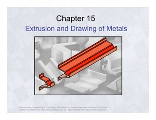
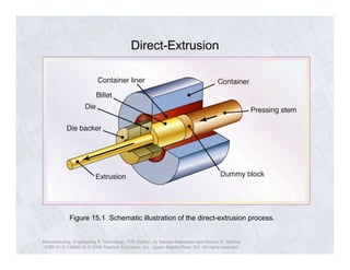
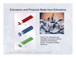


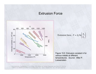
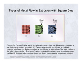

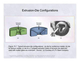
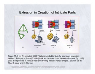


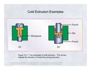
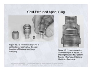
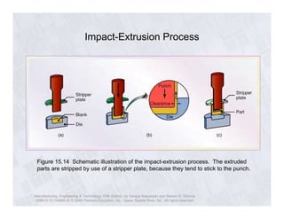
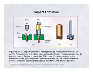
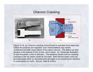
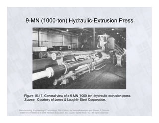
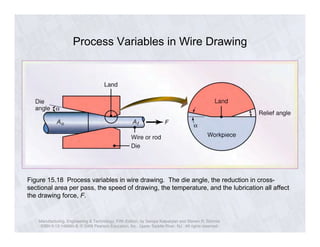
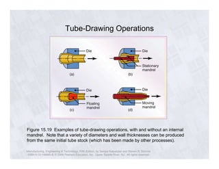
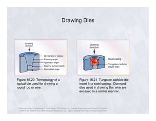
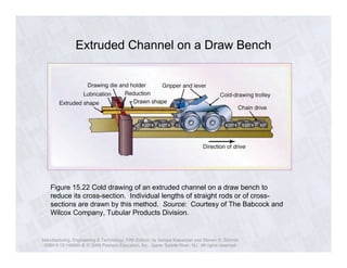

The document discusses various metal forming processes including extrusion and drawing. It describes different types of extrusion such as direct, indirect, and hydrostatic extrusion. Extrusion is used to produce a variety of shapes from metals like aluminum. The document highlights important process variables that affect extrusion pressure and force such as die angle, temperature, and lubrication. It also covers related metal forming techniques such as wire drawing and discusses how process parameters impact drawing force. Diagrams illustrate example applications of extrusion and drawing in manufacturing parts.