Download as PDF, PPTX
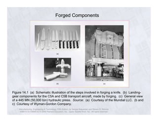


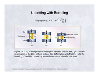
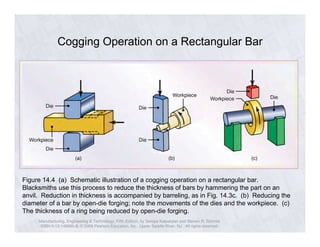


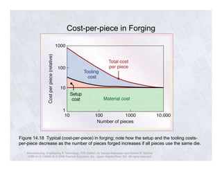


The document discusses the process of forging metals. It describes how forging involves shaping metals using dies or molds by applying compressive forces. It can produce complex shapes and achieve a dense grain structure. Forging is often used to make components that require high strength, such as landing gear or connecting rods. The document outlines various forging techniques including impression die forging, cogging, upsetting, and swaging and discusses how they influence the microstructure and properties of forged parts.


![Forging Process. [Workshop Practices]](https://cdn.slidesharecdn.com/ss_thumbnails/forging-metal-131007035538-phpapp01-thumbnail.jpg?width=640&height=640&fit=bounds)


![Attack surfaces and attack tress[inform]](https://cdn.slidesharecdn.com/ss_thumbnails/lecture03-260108015941-a4dee53b-thumbnail.jpg?width=640&height=640&fit=bounds)


