Download as PDF, PPTX

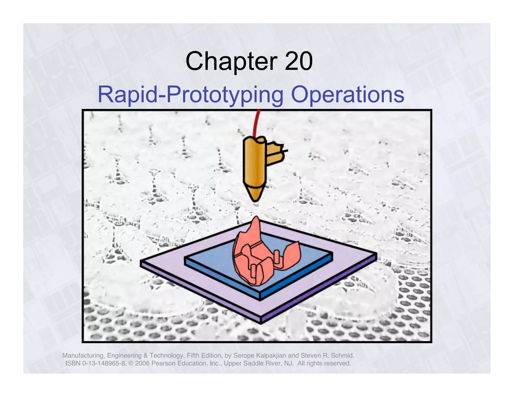
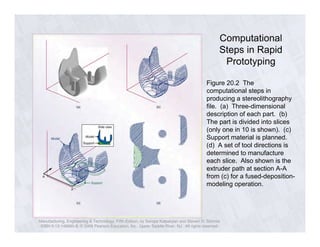
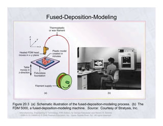
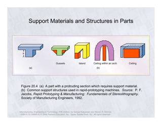
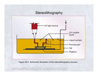


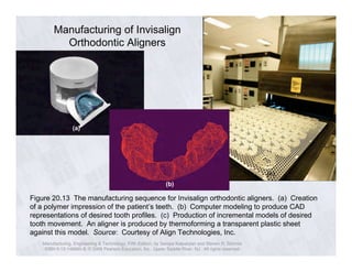
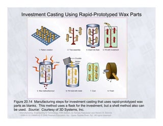
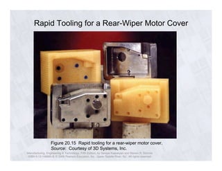

The document discusses rapid prototyping technologies and processes. It describes several additive manufacturing techniques like fused deposition modeling, stereolithography, selective laser sintering, and 3D printing that can be used to quickly create prototype parts directly from 3D CAD files without part-specific tooling. The document also discusses how rapid prototyping can be used to create molds and dies for processes like investment casting and injection molding to enable rapid manufacturing of final parts.


![3D_Printing_Economics_CA[1].ppt](https://cdn.slidesharecdn.com/ss_thumbnails/3dprintingeconomicsca1-231202051828-06e108e9-thumbnail.jpg?width=640&height=640&fit=bounds)


