Download as PDF, PPTX

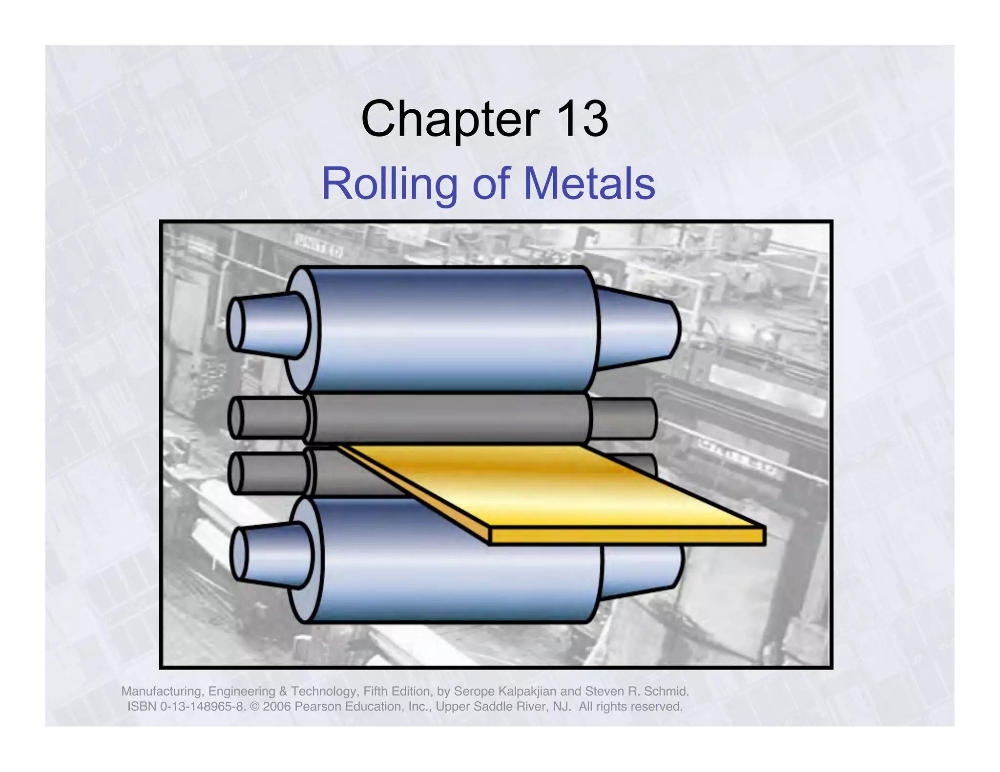
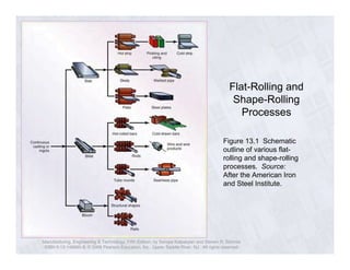
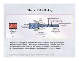
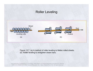

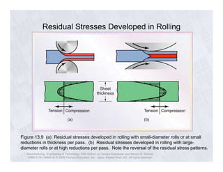
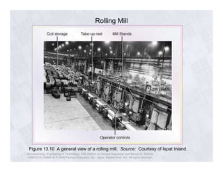
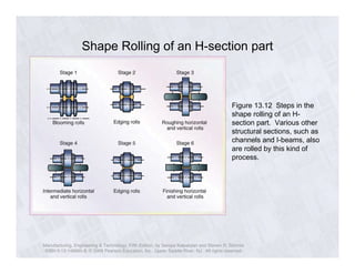
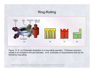
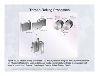
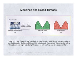
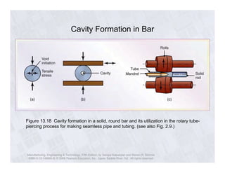
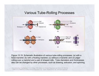
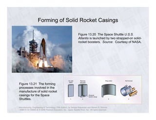

This chapter discusses various metal rolling processes used to shape and form metals. It describes common flat rolling processes which involve passing metal stock through pairs of rolls to reduce thickness. It also covers shape rolling processes used to form structural sections like I-beams. Additional rolling techniques covered include thread rolling, tube rolling, ring rolling, and specialized processes like rocket motor casing forming. The chapter contains diagrams illustrating key aspects of different rolling processes and their use in manufacturing metal parts and products.