Downloaded 199 times
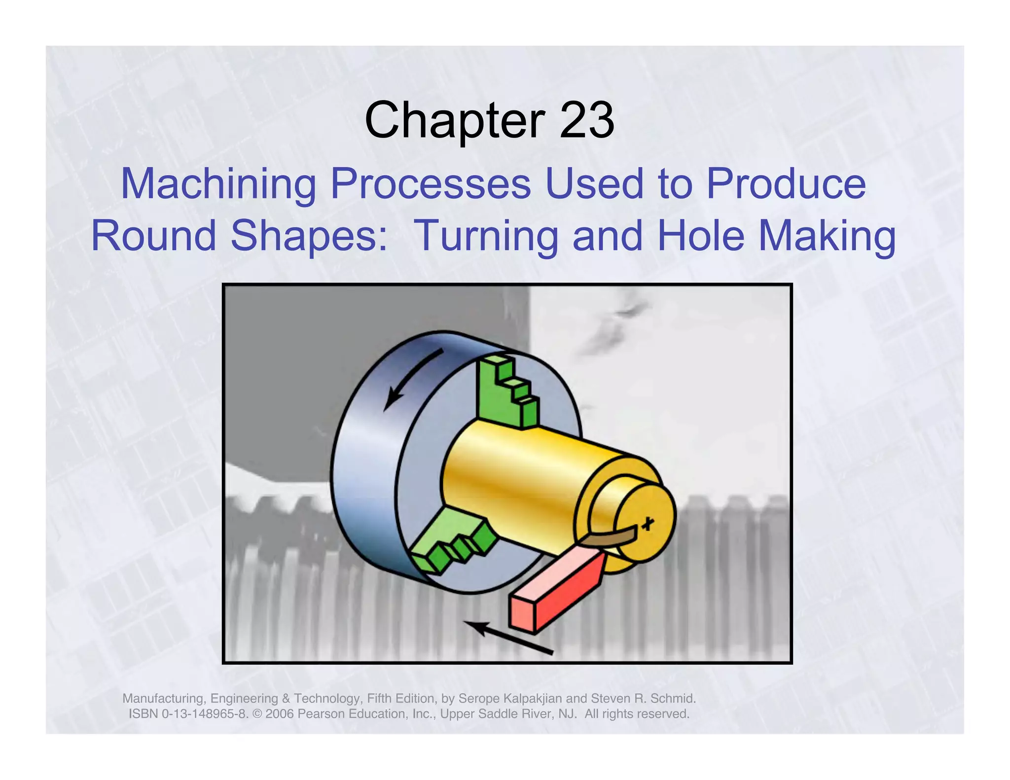
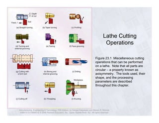
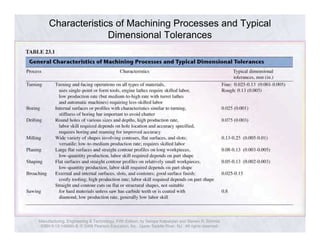
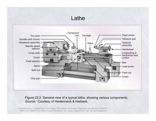
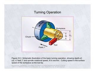
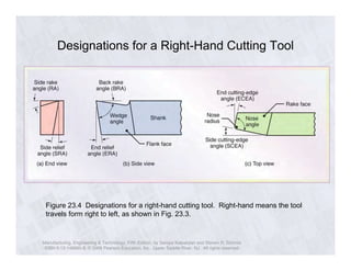
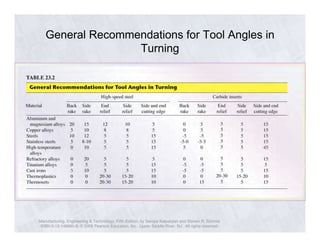
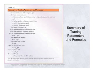
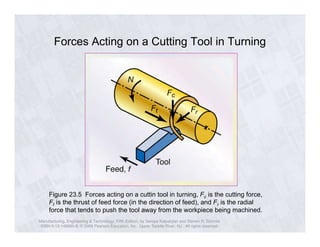
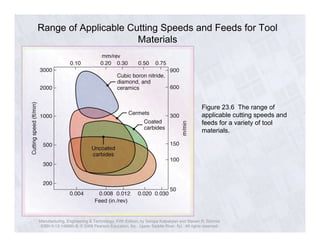
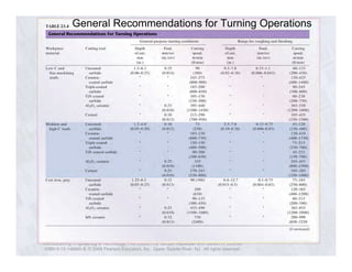
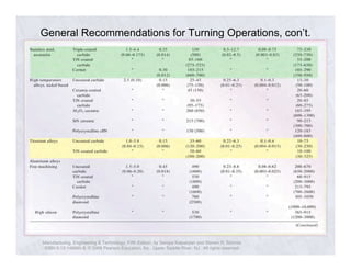
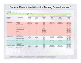
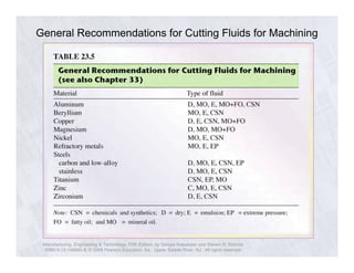
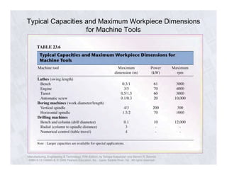
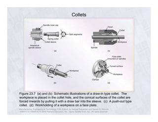
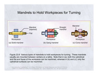
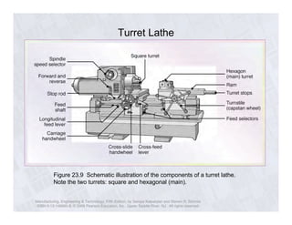
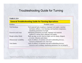
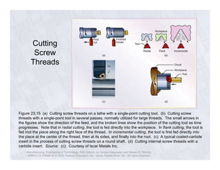
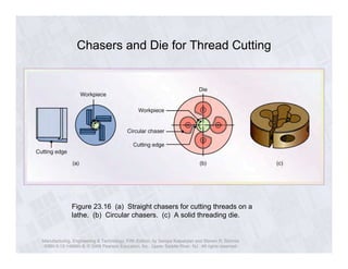

This document discusses machining processes used to produce round shapes, specifically turning and hole making operations. It describes the basic turning operation and details of lathes, including tool angles, forces on cutting tools, recommended cutting speeds and feeds, workholding methods, and troubleshooting guidelines. It also covers cutting screw threads and types of chasers and dies used for thread cutting.