This document provides instructions for completing a Packet Tracer practice skills assessment involving wireless LAN configuration. The steps include:
1. Configuring VLANs, trunking, VTP, and inter-VLAN routing on switches and a router.
2. Modifying STP settings and enabling port security on switch ports.
3. Configuring a wireless LAN including SSID, security, and DHCP services.
4. Verifying connectivity between network devices.
How to create and delete vlan on cisco catalyst switchIT Tech
VLANs create logical broadcast domains that span switches, allowing network administrators to group users independently of physical location. The document provides instructions for creating and deleting VLANs on Cisco Catalyst switches through commands like "vlan", "interface range", and "switchport access vlan" to assign ports to VLANs. It also cautions that one should only manipulate VLANs on production switches after learning on test systems to avoid network issues.
This document provides instructions on configuring a router on a stick topology. It describes configuring a switch port as a trunk, and then creating subinterfaces on the router's physical interface that correspond to each VLAN. It shows assigning IP addresses to the subinterfaces to act as the default gateway for each VLAN subnet. Finally, it describes configuring PCs with IP addresses in the correct subnets and default gateways, and confirms connectivity between the VLANs via ping tests through the router.
Packet Tracer Simulation Lab Layer3 RoutingJohnson Liu
The document describes setting up routing between two routers. It involves:
1. Configuring WAN interfaces on each router and assigning IP addresses between them.
2. Setting up LAN segments behind each router by configuring LAN interfaces and assigning IP addresses.
3. Enabling static routing on each router to allow routing between the LAN segments since dynamic routing protocols have not been configured yet.
This document provides instructions for configuring VLANs and trunking between two switches to allow communication between VLANs. Key steps include creating VLANs 10, 20 and 30 on each switch and assigning ports to each VLAN. A trunk link is configured between the switches to allow traffic to pass between matched VLANs. The functionality is tested by pinging hosts in different VLANs and ports before and after moving them to validate connectivity based on VLAN and trunk configuration.
This document provides instructions for configuring a network with three switches (S1, S2, S3) and three host PCs using various VLANs and Spanning Tree Protocol (STP). The tasks include preparing the network topology, clearing switch configurations, configuring host PCs, enabling VLANs through VTP, configuring trunk links and native VLANs, and verifying STP operation.
Packet Tracer Simulation Lab Layer 2 SwitchingJohnson Liu
The document discusses configuring layer 2 switching and inter-VLAN routing. It describes powering on switches, assigning ports to VLANs, setting up trunk links between switches, and enabling inter-VLAN routing by adding a router with subinterfaces for each VLAN to allow communication between the VLANs.
Cisco CCNA- How to Configure Multi-Layer SwitchHamed Moghaddam
Cisco CCNA Training/Exam Tips that are helpful for your Certification Exam!
To be Cisco Certified please Check out:
http://asmed.com/information-technology-it/
The document discusses Olive, which is the codename for JUNOS software running on a PC rather than a Juniper router. It was originally developed by Juniper as a software development platform before their hardware was fully implemented. The document also discusses logical routers, which allow a single physical router to be partitioned into multiple virtual routers. It provides instructions on configuring logical routers in the Olive VM, including assigning interfaces, enabling OSPF and BGP between the logical routers, and restricting configuration access based on logical router.
Cisco CCNA Training/Exam Tips that are helpful for your Certification Exam!
To be Cisco Certified please Check out:
http://asmed.com/information-technology-it/
This document provides documentation on VLAN configuration commands including vlan, name, switchport pvid, switchport mode, switchport trunk, and show vlan. It describes each command's syntax, parameters, default settings, configuration modes, and examples to configure VLANs and VLAN interfaces on a switch.
This document provides instructions for configuring basic inter-VLAN routing on a network with three switches and one router. Key steps include:
1. Configuring VTP on the switches with one in server mode and two in client mode to propagate VLANs.
2. Creating VLANs 99, 10, 20 and 30 on the VTP server and assigning ports and IP addresses.
3. Configuring the router interface and subinterfaces for each VLAN to enable inter-VLAN routing.
4. Verifying connectivity between VLANs, which now routes through the router instead of failing.
How to configure vlan, stp, dtp step by step guideIT Tech
The document provides step-by-step instructions to configure VLANs, VTP, STP, and DTP on Cisco switches and a router. It describes how to configure a VTP server, create VLANs 10 and 20, assign ports and PCs to each VLAN, configure trunk ports between switches, and configure a router interface for each VLAN to allow inter-VLAN communication. The configurations are verified by checking STP port status and pinging between PCs in different VLANs.
Cisco CCNA/CCNP Training/Exam Tips that are helpful for your Certification Exam!
To be Cisco Certified please Check out:
http://asmed.com/information-technology-it/
Cisco CCNA Training/Exam Tips that are helpful for your Certification Exam!
To be Cisco Certified please Check out:
http://asmed.com/information-technology-it/
Cisco CCNA Training/Exam Tips that are helpful for your Certification Exam!
To be Cisco Certified please Check out:
http://asmed.com/information-technology-it/
This document provides instructions for configuring inter-VLAN routing on a network with three switches and one router. It describes preparing the network topology, configuring basic settings on the devices, creating VLANs on the switches, configuring trunk links and EtherChannels, and using 802.1Q encapsulation on the router interfaces to route between the VLANs. Verification steps are provided to test the configuration at each stage.
This document provides instructions for configuring a Cisco Catalyst 2960 switch. It describes cabling a switch and PC according to a topology diagram and clearing the switch's configuration. The lab steps then guide configuring basic settings on the switch like the hostname, passwords, IP address and default gateway to secure and manage the switch. Verification commands are provided to check the configurations.
This document describes a lab to configure VLANs and trunking between two switches. The objectives are to:
1. Build the network topology and configure basic switch settings.
2. Create VLANs on each switch and assign ports to the appropriate VLAN.
3. Maintain VLAN assignments by changing port VLANs, assigning multiple ports, and removing VLANs.
4. Configure an 802.1Q trunk between the switches to allow traffic from different VLANs to travel across the single link.
This document describes the configuration of basic VLANs on Cisco switches. It provides instructions to:
1. Cable a network topology with three switches and six PCs according to a diagram. Clear the switch configurations and initialize ports.
2. Perform basic switch configurations including hostname, passwords and port assignments.
3. Create VLANs 10, 20, 30 and 99 on the switches and assign names. Assign switch ports on S2 and S3 to the appropriate VLANs.
4. Configure trunking between the switches, setting VLAN 99 as the native VLAN. Verify trunk configuration and switch connectivity.
5. Test connectivity between PCs on different VLANs and subnets before and after moving a PC to
Cisco CCNA Training/Exam Tips that are helpful for your Certification Exam!
To be Cisco Certified please Check out:
http://asmed.com/information-technology-it/
Cisco lab, guide to configure interface stp attributesIT Tech
The document discusses configuring various spanning tree protocol (STP) attributes on interfaces, including:
1) BPDUFilter, which prevents sending and receiving BPDUs on an interface to avoid switching loops.
2) Interface cost, which sets the cost statically to influence the root port election process.
3) Link type, which sets the link as point-to-point or shared to influence rapid transitioning.
4) Port priority, which sets the priority as a tiebreaker for electing the root port among equal cost links.
The lab objectives are to demonstrate configuring these features and verifying their effects on the STP topology.
This document discusses VLANs and their implementation in Cisco switches. It covers VLAN segmentation and types of VLANs, how switches use 802.1Q tagging to identify VLAN traffic on trunk links between switches, and best practices for VLAN security and design including mitigating VLAN hopping and double-tagging attacks. Configuration topics include creating VLANs, assigning ports, configuring trunks, and troubleshooting. The objectives are to explain VLAN purposes, switch forwarding based on VLANs, and configure and secure VLAN environments.
(2) documents e books_cisco_networking_books_training_materials_cnap_-_ont_v5...Lary Onyeka
The document provides instructions for configuring a basic Quality of Service (QoS) test setup using Cisco Pagent tools on routers R1 and TrafGen. Key steps include:
1. Configure the switch port VLANs and router interfaces for traffic between TrafGen and R1.
2. Enter the TGN configuration on TrafGen to generate traffic flows towards R1 and back to TrafGen on various ports.
3. Verify traffic is received and transmitted on R1's interfaces using the show interfaces command.
This document provides an overview of configuring a router, including naming the router, setting passwords, examining show commands, configuring serial and Ethernet interfaces, saving configuration changes, and more. It discusses important topics like using different command modes, setting the clock rate on a serial interface where one router is the data communication equipment (DCE) and provides the clocking signal, and using show commands to examine interface details.
Cisco CCNA/CCNP Training/Exam Tips that are helpful for your Certification Exam!
To be Cisco Certified please Check out:
http://asmed.com/information-technology-it/
This document describes the rapid deployment feature of Pathloss 4.0 software for designing high frequency networks. It allows for automated transmission design, interference analysis under clear and rain conditions, and generation of pathloss data files. The process involves setting a high/low frequency plan, polarizations, running transmission design and interference calculations, and outputting individual pathloss files. It supports both standard and adaptive ATPC radios and can test for network stability under rain interference scenarios.
This document provides an overview of VLAN concepts, configuration, and troubleshooting. It discusses VLAN types and tagging, communicating between VLANs, verifying and saving VLAN configurations, deleting VLANs, and troubleshooting issues such as preventing broadcast storms, establishing trunk links, propagating VLAN changes with VTP, and dropped packets or loops.
Esta presentación muestra el funcionamiento y configuración de "Redistribución" en protocolos de enrutamiento RIP, EIGRP y OSPF. Como configurar una IPSLA y un PBR.
Configuring a gns3 ethernet nio cloud free ccna workbookDare Tintin
This document provides instructions for configuring a GNS3 Ethernet NIO Cloud to allow connectivity between a host machine and devices in a GNS3 topology. It involves installing a Microsoft Loopback adapter on the host, assigning it an IP address, creating a Cloud node in GNS3 and binding it to the Loopback adapter, and connecting the Cloud to a device in the topology. This allows testing connectivity between the host and a device in the topology by pinging the host IP from the device.
CCNA Lab 2-Configuring a Switch Part IIAmir Jafari
This document provides instructions for configuring a Cisco switch, including:
1) Configuring basic port security to restrict access to specific ports and MAC addresses.
2) Enabling SSH on the switch to allow remote access and disabling Telnet for security.
3) Verification steps like showing port security settings, SSH status, and connected users.
Energy resources, energy conversion processes, and reliable energy delivery are the important issues in the 21st century. Smart grid is an intelligent electricity network aimed at providing interoperability between seven different domains: generation, transmission, distribution, customer, operations, markets, and service provider. This new approach is achieved by integration of power systems, advanced communications and information technology. In this paper, the technologies required for the smart will be studied. Different communication technologies, protocols and standards required for various component of smart grid will be identified.
CCNA Lab 3-VLAN Configuration on SwitchAmir Jafari
This document provides instructions for configuring VLANs on a network with three switches and six PCs. It involves:
1) Cabling the network and clearing configurations on the switches.
2) Configuring basic settings like IP addresses and enabling SSH access.
3) Creating VLANs 10, 20, 30, and 99 on each switch and assigning ports to the appropriate VLAN.
4) Configuring trunking between the switches and setting the native VLAN to 99.
5) Verifying the VLAN and trunk configurations using commands like show vlan brief and show interface trunk.
Designing Clocked Synchronous State MachineAbhilash Nair
The document describes the design of a synchronous state machine that detects a 0101 input sequence. It begins with the state diagram and transition table, then derives the excitation and output equations. The circuit diagram shows it uses D-type flip-flops for the state elements and logic gates to generate the next state and output based on the current state and input. It will output a 1 whenever the 0101 sequence is detected in the input stream and a 0 otherwise.
VLAN allows logical separation of broadcast domains by tagging Ethernet frames with VLAN IDs. It divides a physical network into virtual LANs to improve security, manageability and flexibility. VLAN configuration involves assigning ports to VLANs either statically by port number or dynamically by MAC address. Frame tagging standards like IEEE 802.1Q are used to identify VLANs on trunk links that carry traffic for multiple VLANs between switches.
This 3-day routing workshop covers key routing concepts including IP routing, routing protocols, IPv6 addressing, and hands-on exercises. Participants will learn about interior routing protocols like OSPF, exterior routing protocols like BGP, routing attributes, path selection, and scaling techniques. Hands-on labs will provide experience with router configuration, OSPF, iBGP, eBGP, route reflectors, and Internet exchange policies. The goal is to give attendees a solid foundation in routing fundamentals and operations.
This document describes the configuration of a basic BGP routing setup between 6 routers (R2, R3, R4, R5, R6 and 4003) connected through a single switch. It includes the physical and IP addressing configuration of each router interface, as well as the basic BGP configuration including AS numbers and neighbor relationships. It then outlines steps to test connectivity, examine routing tables and BGP neighbors before and after enabling BGP synchronization on one router and applying the next-hop-self command on different routers.
- The document discusses strategies for multihoming service provider networks, including balancing inbound and outbound traffic flows.
- It provides examples of configurations for multihoming with one upstream provider and one local peer, one upstream and a local Internet exchange point, and two upstreams with one local peer.
- Key aspects addressed include announcing address blocks to peers, accepting default routes from upstreams, and using route filters and policies to determine traffic engineering goals.
CCNA R&S-01-Introduction to Cisco Certified Network AssociateAmir Jafari
This document provides an introduction and overview of the Cisco Certified Network Associate (CCNA) certification. It discusses what a network is, who Cisco is as a company, Cisco's products and services, Cisco certifications including the CCNA, IT skills and salaries, exam question types, CCNA exam topics, and resources for CCNA preparation. The document is presented as part of a 40 hour CCNA training course covering topics like Ethernet, switching, routing, WAN technologies and more.
CCCNA R&S-02-The TCP-IP and OSI Networking ModelsAmir Jafari
This document provides an overview of the TCP/IP and OSI networking models. It describes the layers of each model and the key protocols associated with each layer, such as IP, TCP, UDP, Ethernet, and HTTP. It also compares the two models and explains how they were developed with different purposes but provide similar functionality to define rules for network communication.
This document discusses LAN and WAN network architectures. It covers key topics such as:
- LANs are privately owned networks that connect devices within a single building, while WANs provide long-distance transmission across large geographic areas.
- Common LAN technologies include Ethernet, Token Ring, and FDDI, with Ethernet being the most widely used standard.
- WANs connect multiple LANs and use transmission technologies like leased lines, circuits switching, and packet switching to transmit data over large distances.
- The document provides an overview of LAN and WAN components, protocols, topologies and transmission methods.
Design and Implementation of Dynamic Routing in Wireless NetworksSatish Reddy
This document summarizes a student's research on designing and implementing dynamic routing in wireless networks. It discusses several dynamic routing algorithms including SPRA, ECMP, AODV, and proposes a new algorithm called DDRA. DDRA aims to improve security and throughput by routing consecutive packets along different paths instead of the same path. Evaluation shows DDRA has less path similarity, higher throughput, and is less vulnerable to attacks like eavesdropping compared to other algorithms. The document also covers related topics like routing methods, protocols, and a security-enhanced routing table design.
Cisco CCNA exam topics are added to a ppt and shard on this ppt. For more details about Networking Fresher jobs, Fresher Networking Jobs and careers visit www.jobvisions.blogspot.in
Dynamic routing protocols are used to automatically discover remote networks, maintain up-to-date routing information, and choose the best path to destination networks. There are two main types - interior gateway protocols (IGPs) like RIP, OSPF, and EIGRP that are used within an autonomous system, and exterior protocols like BGP that route between autonomous systems. IGPs use metrics like hop count or bandwidth to determine the best path. OSPF is a link-state protocol that floods link information, while EIGRP uses DUAL algorithm and maintains topology tables for fast convergence.
This document provides instructions for configuring basic inter-VLAN routing between VLANs on switches and a router. It includes:
- Configuring VLANs, trunk ports, and IP addresses on switches to segment traffic into VLANs 10, 20, 30, and 99.
- Assigning switch ports, PCs, and a server to the appropriate VLANs and IP subnets.
- Clearing the configuration on a router and preparing it to route between the VLANs.
This document provides summaries of several Cisco IOS commands related to LAN switching, VLANs, trunking, VTP, spanning tree, MAC address tables, and Frame Relay. It begins with brief explanations of commands such as "show interface trunk", "show mac-address-table", "show spanning-tree vlan", "show vlan brief", and "show vtp status", highlighting the key information provided by each command. Configuration commands are also summarized, including examples for setting the VTP domain name, password, and pruning, as well as making a switch the root bridge using "spanning-tree vlan root primary". The document concludes with summaries of Frame Relay commands like "debug frame lmi", "enc
This document discusses configuring VLANs on Cisco switches. It covers VLAN configuration topics like configuring VTP, creating and modifying VLANs, assigning ports to VLANs, configuring trunking, and troubleshooting VLAN issues. The document provides examples of Cisco IOS commands used to configure these features on Catalyst 1900 and Catalyst 2950 switches. It also describes show commands used to verify proper VLAN, VTP, and trunking operation.
The document contains configuration details of a main router and main switch used to connect different departments using VLAN encapsulation. The router configuration shows 11 VLAN interfaces configured for IP addresses on FastEthernet0/0, while the switch configuration shows each port assigned to a specific VLAN and the VLAN database output listing the 11 VLANs.
This document provides instructions for a practical exercise to configure PVST+ and Rapid PVST+ on three switches (S1, S2, S3) connected in a topology. The objectives are to:
1) Configure VLANs, trunk ports, and management interfaces on each switch.
2) Configure PVST+ and optimize the topology by making one switch the primary root for certain VLANs.
3) Configure PortFast and BPDU Guard to accelerate connection of end-user devices.
4) Repeat the configuration using Rapid PVST+ and observe the faster convergence times.
This document describes a lab that configures Rapid PVST+, PortFast, and BPDU Guard on a network with three switches (S1, S2, S3) and two PCs (PC-A, PC-C). The lab has four parts: 1) build the network and configure basic settings, 2) configure VLANs, native VLAN, and trunks, 3) configure the root bridge and examine PVST+ convergence, and 4) configure Rapid PVST+, PortFast, BPDU Guard, and examine convergence. The objectives are to optimize network performance by configuring Rapid PVST+ for faster convergence, and configure PortFast and BPDU Guard on edge ports.
The document discusses securing a private network environment using Network Address Translation (NAT). It summarizes the configuration of routers, switches, and NAT for three separate organizations (Org1, Org2, Org3) to allow internal clients to access the internet through public IP addresses while protecting private servers. VLANs are used to separate server and client networks in each organization. NAT is configured on the routers to translate private to public IP addresses for internal clients to access the internet and expose specific internal servers to the internet.
The document summarizes how to configure and manage a Catalyst switch, including:
- Verifying default settings such as the hostname and VLAN configuration
- Configuring IP addresses, passwords, and interfaces
- Viewing and managing the MAC address table
- Configuring static MAC addresses and port security to restrict which devices can connect to ports
- Procedures are provided for tasks like setting port speeds and enabling the web interface
The document provides useful commands for configuring VLANs, routing, and displaying information on an Aruba Mobility Access Switch. It includes commands for creating VLANs, assigning ports, IP addresses, switching profiles, trunking, routing, DHCP, and display commands for viewing VLAN, interface, and routing information.
This document describes the configuration of VLANs on a Cisco switch. The key steps are:
1. Six VLANs are created and named for different departments.
2. Ports on the switch are assigned to each VLAN to segregate network traffic for each department.
3. IP addresses are configured for each VLAN interface and routing is enabled with RIP to allow communication between VLANs.
4. Ping tests confirm connectivity between devices on different VLANs, showing the VLAN configuration is functioning properly.
- The document describes how to clear the configuration of a switch connected to other switches to prepare it for a new lab. This involves erasing the startup configuration from NVRAM, deleting the VLAN database, shutting down interfaces, removing VLANs, and optionally configuring transparent VTP mode to prevent VLANs from being relearned.
CCNA R&S-13-Spanning Tree Protocol ImplementationAmir Jafari
This document discusses configuration and verification of Spanning Tree Protocol (STP) on Cisco switches. It covers topics such as setting the STP mode, configuring port costs and priorities to influence the root election, enabling PortFast and BPDU guard, and configuring EtherChannel. Configuration examples are provided to demonstrate how to view STP status using show commands and manipulate the STP topology by adjusting port costs and switch priorities.
This document describes configuring PVST+ spanning tree protocol on a network topology. It involves:
1. Configuring VLANs, trunk ports between switches, and IP addresses for switch management.
2. Optimizing the spanning tree configuration by making one switch the primary root for certain VLANs and another the secondary root to load balance traffic across trunks.
3. Enabling PortFast on end-user ports to quickly forward traffic and BPDU guard to protect against devices connected to those ports influencing the spanning tree.
This document provides instructions for configuring Cisco Catalyst switches to connect Cisco IP phones. It discusses:
1) Configuring switch ports to carry both voice and data traffic on separate VLANs using predefined macros. It also covers configuring inline power, QoS, and verifying the configuration.
2) Troubleshooting issues like phones not receiving power or IP addresses correctly.
3) Background information on Cisco IP phone port connections and how switches prioritize voice traffic using QoS markings to maintain call quality.
Creating ethernet vla ns on catalyst switchesabeforu
Creating Ethernet VLANs on Catalyst Switches
1. Define a VTP domain name to configure the VLAN Trunking Protocol settings before creating VLANs. 2. Create VLANs using the "set vlan" command and verify the VLAN configuration using "show vlan". 3. Assign switch ports to VLANs using "set vlan vlan_number mod/ports" to associate the ports with the VLAN.
Configure the ACME headquarters network and New York office network per the requirements:
- Set the VTP domain to CCIE and use VTP version 2 on all switches
- Configure SW1 as the VTP server and SW2 as the client for the headquarters network
- Configure SW3 and SW4 as VTP transparent mode for the New York office network
- Secure VTP with the specified MD5 passwords on each network
- Configure access ports and trunk ports between switches to establish VLANs and allow connectivity between routers
This document provides an overview of wound healing, its functions, stages, mechanisms, factors affecting it, and complications.
A wound is a break in the integrity of the skin or tissues, which may be associated with disruption of the structure and function.
Healing is the body’s response to injury in an attempt to restore normal structure and functions.
Healing can occur in two ways: Regeneration and Repair
There are 4 phases of wound healing: hemostasis, inflammation, proliferation, and remodeling. This document also describes the mechanism of wound healing. Factors that affect healing include infection, uncontrolled diabetes, poor nutrition, age, anemia, the presence of foreign bodies, etc.
Complications of wound healing like infection, hyperpigmentation of scar, contractures, and keloid formation.
Beyond Degrees - Empowering the Workforce in the Context of Skills-First.pptxEduSkills OECD
Iván Bornacelly, Policy Analyst at the OECD Centre for Skills, OECD, presents at the webinar 'Tackling job market gaps with a skills-first approach' on 12 June 2024
Temple of Asclepius in Thrace. Excavation resultsKrassimira Luka
The temple and the sanctuary around were dedicated to Asklepios Zmidrenus. This name has been known since 1875 when an inscription dedicated to him was discovered in Rome. The inscription is dated in 227 AD and was left by soldiers originating from the city of Philippopolis (modern Plovdiv).
Level 3 NCEA - NZ: A Nation In the Making 1872 - 1900 SML.pptHenry Hollis
The History of NZ 1870-1900.
Making of a Nation.
From the NZ Wars to Liberals,
Richard Seddon, George Grey,
Social Laboratory, New Zealand,
Confiscations, Kotahitanga, Kingitanga, Parliament, Suffrage, Repudiation, Economic Change, Agriculture, Gold Mining, Timber, Flax, Sheep, Dairying,
A Visual Guide to 1 Samuel | A Tale of Two HeartsSteve Thomason
These slides walk through the story of 1 Samuel. Samuel is the last judge of Israel. The people reject God and want a king. Saul is anointed as the first king, but he is not a good king. David, the shepherd boy is anointed and Saul is envious of him. David shows honor while Saul continues to self destruct.
Leveraging Generative AI to Drive Nonprofit InnovationTechSoup
In this webinar, participants learned how to utilize Generative AI to streamline operations and elevate member engagement. Amazon Web Service experts provided a customer specific use cases and dived into low/no-code tools that are quick and easy to deploy through Amazon Web Service (AWS.)
Leveraging Generative AI to Drive Nonprofit Innovation
Ccna 4 final lab switchi
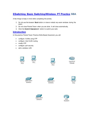
1. ESwitching Basic Switching/Wireless PT Practice SBA
A few things to keep in mind while completing this activity:
1. Do not use the browser Back button or close or reload any exam windows during the
exam.
2. Do not close Packet Tracer when you are done. It will close automatically.
3. Click the Submit Assessment button to submit your work.
Introduction
In this practice Packet Tracer Practice Skills Based Assement, you will:
configure VLANs using VTP
configure inter-VLAN routing
modify STP
configure port security
add a wireless LAN
2. Addressing Table
Device Interface Address Subnet Mask Default Gateway
Branch
Fa0/0.40 10.10.40.1 255.255.255.0 n/a
Fa0/0.50 10.10.50.1 255.255.255.0 n/a
Fa0/0.55 10.10.55.1 255.255.255.0 n/a
Fa0/0.80 10.10.80.1 255.255.255.0 n/a
WLAN
Internet 10.10.80.10 255.255.255.0 10.10.80.1
Wireless 10.10.100.1 255.255.255.0 n/a
S1 VLAN 55 10.10.55.11 255.255.255.0 10.10.55.1
S2 VLAN 55 10.10.55.12 255.255.255.0 10.10.55.1
S3 VLAN 55 10.10.55.13 255.255.255.0 10.10.55.1
Staff 1 NIC 10.10.40.10 255.255.255.0 10.10.40.1
Staff 2 NIC 10.10.40.11 255.255.255.0 10.10.40.1
Admin NIC 10.10.50.10 255.255.255.0 10.10.50.1
WRS PC NIC DHCP assigned 255.255.255.0 10.10.100.1
Note: The password for user EXEC mode is cisco. The password for privileged EXEC mode
is class.
Step 1: Configure the Switches for Remote Access.
Create, enable, and address VLAN 55 as the management interface on all three switches. Use
the values found in the addressing table.
Step 2: Configure Trunking.
Note: Packet Tracer now supports the use of the range argument for the interface command.
For interfaces FastEthernet 0/1 through FastEthernet 0/4 on all three switches:
Configure static trunking.
Assign VLAN 55 as the native VLAN.
3. S3(config)#interface RAnge fastEthernet 0/1-4
S3(config-if-range)#sw
S3(config-if-range)#switchport mod
S3(config-if-range)#switchport mode tru
S3(config-if-range)#switchport mode trunk
%LINEPROTO-5-UPDOWN: Line protocol on Interface FastEthernet0/1, changed state to down
%LINEPROTO-5-UPDOWN: Line protocol on Interface FastEthernet0/1, changed state to up
%LINEPROTO-5-UPDOWN: Line protocol on Interface FastEthernet0/2, changed state to down
%LINEPROTO-5-UPDOWN: Line protocol on Interface FastEthernet0/2, changed state to up
%LINEPROTO-5-UPDOWN: Line protocol on Interface FastEthernet0/3, changed state to down
%LINEPROTO-5-UPDOWN: Line protocol on Interface FastEthernet0/3, changed state to up
%LINEPROTO-5-UPDOWN: Line protocol on Interface FastEthernet0/4, changed state to down
%LINEPROTO-5-UPDOWN: Line protocol on Interface FastEthernet0/4, changed state to up
S3(config-if-range)#sw
S3(config-if-range)#switchport tru
S3(config-if-range)#switchport trunk
S3(config-if-range)#switchport trunk native vl
S3(config-if-range)#switchport trunk native vlan 55
S3(config-if-range)#no shu
S3(config-if-range)#no shutdown
S3(config-if-range)#exit
S3(config)#
Step 3: Configure VTP and VLANs.
a. Configure S1 as VTP server and the following VTP parameters:
S1 is the VTP server.
4. VTP domain name: BRANCH
VTP password: vtpbranch
S1(config)#vtp mode ser
S1(config)#vtp mode server
Device mode already VTP SERVER.
S1(config)#vt
S1(config)#vtp dom
S1(config)#vtp domain BRANCH
Changing VTP domain name from NULL to BRANCH
S1(config)#vtp
S1(config)#vtp pass
S1(config)#vtp password vtpbranch
Setting device VLAN database password to vtpbranch
b. Create and name the following VLANs on S1.
VLAN 40: Staff
VLAN 50: Admin
VLAN 55: Management
VLAN 80: Wireless
S1(config)#vl
S1(config)#vlan 40
S1(config-vlan)#na
S1(config-vlan)#name Staff
S1(config-vlan)#exit
S1(config)#vl
S1(config)#vlan 50
S1(config-vlan)#na
S1(config-vlan)#name Admin
S1(config-vlan)#vl
S1(config-vlan)#exit
S1(config)#vl
S1(config)#vlan 55
%LINK-5-CHANGED: Interface Vlan55, changed state to up
%LINEPROTO-5-UPDOWN: Line protocol on Interface Vlan55, changed state to up
S1(config-vlan)#na
S1(config-vlan)#name Management
S1(config-vlan)#exit
S1(config)#vl
S1(config)#vlan 88
S1(config-vlan)#nam
S1(config-vlan)#name Wireless
S1(config-vlan)#exit
S1(config)#exit
S1#
5. c. Configure S2 and S3 as VTP clients to participate in the BRANCH VTP domain.
S2(config)#vtp mod
S2(config)#vtp mode cli
S2(config)#vtp mode client
Setting device to VTP CLIENT mode.
S2(config)#vt
S2(config)#vtp pass
S2(config)#vtp dom
S2(config)#vtp domain BRANCH
Domain name already set to BRANCH.
S2(config)#vtp
S2(config)#vtp pass
S2(config)#vtp password vtpbranch
Setting device VLAN database password to vtpbranch
S2(config)#
%LINK-5-CHANGED: Interface Vlan55, changed state to up
%LINEPROTO-5-UPDOWN: Line protocol on Interface Vlan55, changed state to up
S2(config)#exot
^
% Invalid input detected at '^' marker.
S2(config)#
S2(config)#exit
S2#
S3(config)#vtp mod
S3(config)#vtp mode cli
S3(config)#vtp mode client
Setting device to VTP CLIENT mode.
S3(config)#vtp
S3(config)#vtp bran
S3(config)#vtp doma
S3(config)#vtp domain BRANCH
Domain name already set to BRANCH.
S3(config)#vtp
S3(config)#vtp pass
S3(config)#vtp password vtpbranch
Setting device VLAN database password to vtpbranch
S3(config)#
%LINK-5-CHANGED: Interface Vlan55, changed state to up
%LINEPROTO-5-UPDOWN: Line protocol on Interface Vlan55, changed state to up
6. S3(config)#exit
S3#
%SYS-5-CONFIG_I: Configured from console by console
S3#
d. Verify that VTP is operational.
S3#ping 10.10.55.13
Type escape sequence to abort.
Sending 5, 100-byte ICMP Echos to 10.10.55.13, timeout is 2 seconds:
!!!!!
Success rate is 100 percent (5/5), round-trip min/avg/max = 0/1/2 ms
S3#ping 10.10.55.12
Type escape sequence to abort.
Sending 5, 100-byte ICMP Echos to 10.10.55.12, timeout is 2 seconds:
..!!!
Success rate is 60 percent (3/5), round-trip min/avg/max = 8/8/8 ms
S3#ping 10.10.55.11
Type escape sequence to abort.
Sending 5, 100-byte ICMP Echos to 10.10.55.11, timeout is 2 seconds:
..!!!
Success rate is 60 percent (3/5), round-trip min/avg/max = 4/4/4 ms
S3#
Step 4: Configure Interfaces for VLAN Access
VLAN port assignments on each switch are as follows:
7. Device Ports Assignment
S2, S3 Fa0/1 – 0/10 40
S2, S3 Fa0/11 – 0/17 50
S3 Fa0/18 80
a. Configure access ports on access layer switches.
Configure the appropriate interfaces on S2 and S3 for access mode.
Assign VLANs according to the port assignments table.
b. Verify trunking and VLAN assignments.
S3(config)#inter
S3(config)#interface fa
S3(config)#interface fastEthernet 0/6
S3(config-if)#sw
S3(config-if)#switchport mod
S3(config-if)#switchport mode acc
S3(config-if)#switchport mode access
S3(config-if)#swe
S3(config-if)#sw
S3(config-if)#switchport acc
S3(config-if)#switchport access vl
S3(config-if)#switchport access vlan 40
S3(config-if)#no shu
S3(config-if)#no shutdown
S3(config-if)#exit
Step 5: Configure Spanning Tree.
a. Modify STP root bridge elections.
Using a priority of 12288, set S1 as the root bridge for all VLANs.
Using a priority of 16384, set S2 so that it will become the root for all VLANs if S1 fails.
b. Verify the spanning tree election.
S1(config)#spanning-tree vlan 1-99 priority 12288
S1(config)#spanning-tree vlan 1-99 prio
S1(config)#spanning-tree vlan 1-99 root pri
S1(config)#spanning-tree vlan 1-99 root primary
S1(config)#
S1(config)#
S2(config)#spanning-tree vlan 1-99 priority 16384
S2(config)#spanning-tree vlan 1-99 root secondary
S2(config)#exit
8. Step 6: Configure Inter-VLAN Routing.
Use the information in the Addressing Table to configure Branch for inter-VLAN routing.
Be sure to designate the native VLAN.
Verify inter-VLAN routing.
S1(config)#interface fastEthernet 0/5
S1(config-if)#sw
S1(config-if)#switchport mod
S1(config-if)#switchport mode trunk
S1(config-if)#no shu
S1(config-if)#no shutdown
S1(config-if)#exit
BRANCH(config)#inter
BRANCH(config)#interface fa
BRANCH(config)#interface fastEthernet 0/0.40
BRANCH(config-subi f)#ip add
BRANCH(config-subi f)#ip address 10.10.40.1 255.255.255.0
BRANCH(config-subi f)#encap
BRANCH(config-subi f)#encapsulation do
BRANCH(config-subi f)#encapsulation dot1Q 40
BRANCH(config-subi f)#no sh
BRANCH(config-subi f)#no shutdown
BRANCH(config-subi f)#exit
BRANCH(config)#interface fastEthernet 0/0.50
BRANCH(config-subi f)#ip add
BRANCH(config-subi f)#ip address 10.10.50.1 255.255.255.0
BRANCH(config-subi f)#encap
BRANCH(config-subi f)#encapsulation do
BRANCH(config-subi f)#encapsulation dot1Q 50
BRANCH(config-subi f)#no shu
BRANCH(config-subi f)#no shutdown
BRANCH(config-subi f)#exit
BRANCH(config)#inter
BRANCH(config)#interface fa
BRANCH(config)#interface fastEthernet 0/0.55
BRANCH(config-subi f)#ip add
BRANCH(config-subi f)#ip address 10.10.55.1 255.255.255.0
BRANCH(config-subi f)#encap
BRANCH(config-subi f)#encapsulation do
BRANCH(config-subi f)#encapsulation dot1Q 55
BRANCH(config-subi f)#no shu
BRANCH(config-subi f)#no shutdown
9. BRANCH(config-subi f)#exit
BRANCH(config)#inter
BRANCH(config)#interface fa
BRANCH(config)#interface fastEthernet 0/0.80
BRANCH(config-subi f)#ip add
BRANCH(config-subi f)#ip address 10.10.80.1 255.255.255.0
BRANCH(config-subi f)#encap
BRANCH(config-subi f)#encapsulation do
BRANCH(config-subi f)#encapsulation dot1Q 80
BRANCH(config-subi f)#no0 shu
Step 7: Configure Port Security.
Note: Best practice requires port security on all access ports. However, for this practice
exercise you will only configure one port with security.
a. Configure S3 with port security on FastEthernet 0/2.
Enable port security.
No more than two MAC addresses are allowed on the FastEthernet 0/2 port for S3.
Once learned, MAC addresses should be automatically added to the running configuration.
If this policy is violated, the port should be automatically disabled.
b. Verify that port security is implemented.
S2(config-if)#switchport por
S2(config-if)#switchport port-security ?
mac-address Secure mac address
maximum Max secure addresses
violation Security violation mode
<cr>
S2(config-if)#switchport port-security ma
S2(config-if)#switchport port-security mac-address sticky
S2(config-if)#sw
S2(config-if)#switchport por
S2(config-if)#switchport port-security max
S2(config-if)#switchport port-security maximum 1
S2(config-if)#sw
S2(config-if)#switchport por
S2(config-if)#switchport port-security vio
S2(config-if)#switchport port-security violation ?
protect Security violation protect mode
restrict Security violation restrict mode
shutdown Security violation shutdown mode
S2(config-if)#switchport port-security violation sh
S2(config-if)#switchport port-security violation shutdown
S2(config-if)#no shu
S2(config-if)#no shutdown
10. S2(config-if)#exit
S2(config)#
S2#show port-security interface fastEthernet 0/5
Port Security : Enabled
Port Status : Secure-up
Violation Mode : Shutdown
Aging Time : 0 mins
Aging Type : Absolute
SecureStatic Address Aging : Disabled
Maximum MAC Addresses : 1
Total MAC Addresses : 0
Configured MAC Addresses : 0
Sticky MAC Addresses : 0
Last Source Address:Vlan : 0000.0000.0000:0
Security Violation Count : 0
S2#
Step 8: Configure the Wireless LAN.
Refer to the Addressing Table to configure the wireless LAN.
a. Configure WLAN.
Use static addressing on the Internet interface.
Set the router IP and subnet mask.
Use the DHCP Server Settings to configure the router to provide wireless hosts with an IP
address.
The starting IP address in the wireless LAN subnet is 10.10.100.15.
The maximum number of users is 75.
b. Configure wireless security.
Set the SSID to Branch_WLAN.
Enable WEP security and use 0123456789 as key1.
c. Use branch123 as the remote management password.
d. Configure WRS PC to access the wireless network that is provided by WLAN. WRS PC uses
DHCP to obtain addressing information.
Note: It will not be possible for devices to ping WRS PC since WRS PC is behind the WLAN
NAT firewall.
Step 9: Verify Connectivity.
Although these are not scored, the following connectivity tests should be successful.
S1 can ping Branch.
S1#
S1#ping 10.10.55.1
Type escape sequence to abort.
11. Sending 5, 100-byte ICMP Echos to 10.10.55.1, timeout is 2 seconds:
.!!!!
Success rate is 80 percent (4/5), round-trip min/avg/max = 3/4/5 ms
S1#ping 10.10.50.1
Type escape sequence to abort.
Sending 5, 100-byte ICMP Echos to 10.10.50.1, timeout is 2 seconds:
!!!!!
Success rate is 100 percent (5/5), round-trip min/avg/max = 3/4/5 ms
S1#ping 10.10.40.1
Type escape sequence to abort.
Sending 5, 100-byte ICMP Echos to 10.10.40.1, timeout is 2 seconds:
!!!!!
Success rate is 100 percent (5/5), round-trip min/avg/max = 2/3/5 ms
S1#ping 10.10.80.1
Type escape sequence to abort.
Sending 5, 100-byte ICMP Echos to 10.10.80.1, timeout is 2 seconds:
!!!!!
Success rate is 100 percent (5/5), round-trip min/avg/max = 3/4/5 ms
S2 can ping Branch.
S2>ping 10.10.55.1
Type escape sequence to abort.
Sending 5, 100-byte ICMP Echos to 10.10.55.1, timeout is 2 seconds:
.!!!!
Success rate is 80 percent (4/5), round-trip min/avg/max = 7/7/8 ms
S2>ping 10.10.40.1
Type escape sequence to abort.
Sending 5, 100-byte ICMP Echos to 10.10.40.1, timeout is 2 seconds:
!!!!!
Success rate is 100 percent (5/5), round-trip min/avg/max = 7/8/9 ms
S2>ping 10.10.80.1
Type escape sequence to abort.
Sending 5, 100-byte ICMP Echos to 10.10.80.1, timeout is 2 seconds:
!!!!!
Success rate is 100 percent (5/5), round-trip min/avg/max = 7/8/9 ms
12. S2>ping 10.10.50.1
Type escape sequence to abort.
Sending 5, 100-byte ICMP Echos to 10.10.50.1, timeout is 2 seconds:
!!!!!
Success rate is 100 percent (5/5), round-trip min/avg/max = 7/7/9 ms
S3 can ping Branch.
S3#ping 10.10.55.1
Type escape sequence to abort.
Sending 5, 100-byte ICMP Echos to 10.10.55.1, timeout is 2 seconds:
.!!!!
Success rate is 80 percent (4/5), round-trip min/avg/max = 7/7/9 ms
S3#ping 10.10.50.1
Type escape sequence to abort.
Sending 5, 100-byte ICMP Echos to 10.10.50.1, timeout is 2 seconds:
!!!!!
Success rate is 100 percent (5/5), round-trip min/avg/max = 7/8/9 ms
S3#ping 10.10.40.1
Type escape sequence to abort.
Sending 5, 100-byte ICMP Echos to 10.10.40.1, timeout is 2 seconds:
!!!!!
Success rate is 100 percent (5/5), round-trip min/avg/max = 7/7/9 ms
S3#ping 10.10.80.1
Type escape sequence to abort.
Sending 5, 100-byte ICMP Echos to 10.10.80.1, timeout is 2 seconds:
!!!!!
Success rate is 100 percent (5/5), round-trip min/avg/max = 7/7/9 ms
S3#
Staff 1 can ping Admin.
PC>ipconfig
IP Address......................: 10.10.40.10
Subnet Mask.....................: 255.255.255.0
Default Gateway.................: 10.10.40.1
PC>ping 10.10.50.10
Pinging 10.10.50.10 with 32 bytes of data:
13. Reply from 10.10.50.10: bytes=32 time=28ms TTL=127
Reply from 10.10.50.10: bytes=32 time=22ms TTL=127
Reply from 10.10.50.10: bytes=32 time=26ms TTL=127
Reply from 10.10.50.10: bytes=32 time=23ms TTL=127
Ping statistics for 10.10.50.10:
Packets: Sent = 4, Received = 4, Lost = 0 (0% loss),
Approximate round trip times in milli-seconds:
Minimum = 22ms, Maximum = 28ms, Average = 24ms
PC>10
Admin can ping Staff 2.
PC>ipconfig
IP Address......................: 10.10.50.10
Subnet Mask.....................: 255.255.255.0
Default Gateway.................: 10.10.50.1
PC>ping 10.10.40.11
Pinging 10.10.40.11 with 32 bytes of data:
Request timed out.
Reply from 10.10.40.11: bytes=32 time=23ms TTL=127
Reply from 10.10.40.11: bytes=32 time=22ms TTL=127
Ping statistics for 10.10.40.11:
Packets: Sent = 4, Received = 3, Lost = 1 (25% loss),
Approximate round trip times in milli-seconds:
Minimum = 22ms, Maximum = 23ms, Average = 22ms
PC>
WRS PC can ping Staff 1.
ROUTER AND SWITCH CONFIGURATION:
BRANCH#show startup-config
Using 808 bytes
!
14. version 12.4
no service timestamps log datetime msec
no service timestamps debug datetime msec
no service password-encryption
!
hostname BRANCH
!
!
!
!
interface FastEthernet0/0
no ip address
duplex auto
speed auto
!
interface FastEthernet0/0.40
encapsulation dot1Q 40
ip address 10.10.40.1 255.255.255.0
!
interface FastEthernet0/0.50
encapsulation dot1Q 50
ip address 10.10.50.1 255.255.255.0
!
interface FastEthernet0/0.55
encapsulation dot1Q 55
ip address 10.10.55.1 255.255.255.0
!
interface FastEthernet0/0.80
encapsulation dot1Q 80
ip address 10.10.80.1 255.255.255.0
!
interface FastEthernet0/1
no ip address
duplex auto
speed auto
shutdown
!
interface Vlan1
no ip address
shutdown
!
ip classless
!
!
!
!
!
!
!
line con 0
line vty 0 4
login
!
!
!
end