
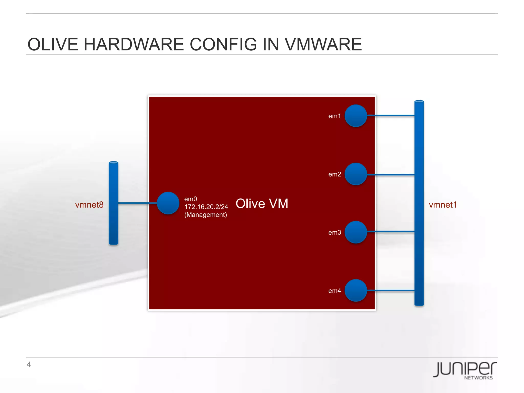
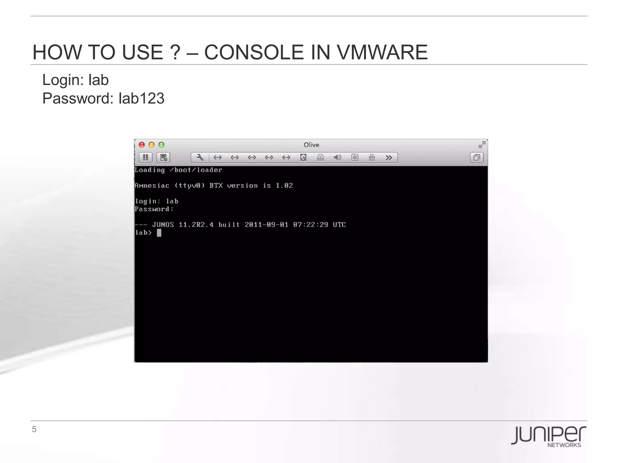
![Check interface in olive
At first, let’s see what interface we have, in baseline.conf I had pre-configured four
interface for use(except the em0 for management purpose):
[edit]
lab# run show interfaces terse
Interface Admin Link Proto Local Remote
em0 up up
em0.0 up up inet 172.16.20.2/24
em1 up up
em2 up up
em3 up up
em4 up up](https://image.slidesharecdn.com/olive-120910105545-phpapp01/75/Olive-Introduction-for-TOI-7-2048.jpg)
![Setup 1st Logical router
Now, I decide to setup a logical router(called WR) which will use the interface
em1.10 and loopback0.1 :
[edit]
lab# set logical-systems WR interfaces em1 unit 10 vlan-id 10
lab# set logical-systems WR interfaces em1 unit 10 family inet address 10.10.10.1/24
lab# set logical-systems WR interfaces lo0.1 family inet address 1.1.1.1/32
Lab# commit
lab# show logical-systems WR
interfaces {
em1 {
unit 10 {
vlan-id 10;
family inet {
address 10.10.10.1/24;
}
}
}
lo0 {
unit 1 {
family inet {
address 1.1.1.1/32;
}
}
}
}](https://image.slidesharecdn.com/olive-120910105545-phpapp01/75/Olive-Introduction-for-TOI-8-2048.jpg)
![Setup 2nd Logical router
Then, I setup a logical router(called VPN) which will use the interface em2.10 and
loopback0.2 :
[edit]
lab# set logical-systems VPN interfaces em2 unit 10 vlan-id 10
lab# set logical-systems VPN interfaces em2 unit 10 family inet address 10.10.10.2/24
lab# set logical-systems VPN interfaces lo0.2 family inet address 2.2.2.2/32
Lab# commit
lab# show logical-systems VPN
interfaces {
em2 {
unit 10 {
vlan-id 10;
family inet {
address 10.10.10.2/24;
}
}
}
lo0 {
unit 2 {
family inet {
address 2.2.2.2/32;
}
}
}
}](https://image.slidesharecdn.com/olive-120910105545-phpapp01/75/Olive-Introduction-for-TOI-9-2048.jpg)
![TEST Logical routers’ connection
NOW, test the logical router WAN interface reachability:
[edit]
lab# run ping logical-system WR 10.10.10.2
PING 10.10.10.2 (10.10.10.2): 56 data bytes
64 bytes from 10.10.10.2: icmp_seq=0 ttl=64 time=1.026 ms
64 bytes from 10.10.10.2: icmp_seq=1 ttl=64 time=0.355 ms
64 bytes from 10.10.10.2: icmp_seq=2 ttl=64 time=0.313 ms
64 bytes from 10.10.10.2: icmp_seq=3 ttl=64 time=0.298 ms
^C
--- 10.10.10.2 ping statistics ---
4 packets transmitted, 4 packets received, 0% packet loss
round-trip min/avg/max/stddev = 0.298/0.498/1.026/0.306 ms
lab# run show route logical-system WR
inet.0: 3 destinations, 3 routes (3 active, 0 holddown, 0 hidden)
+ = Active Route, - = Last Active, * = Both
1.1.1.1/32 *[Direct/0] 00:06:08
> via lo0.1
10.10.10.0/24 *[Direct/0] 00:06:08
> via em1.10
10.10.10.1/32 *[Local/0] 00:06:08
Local via em1.10](https://image.slidesharecdn.com/olive-120910105545-phpapp01/75/Olive-Introduction-for-TOI-10-2048.jpg)
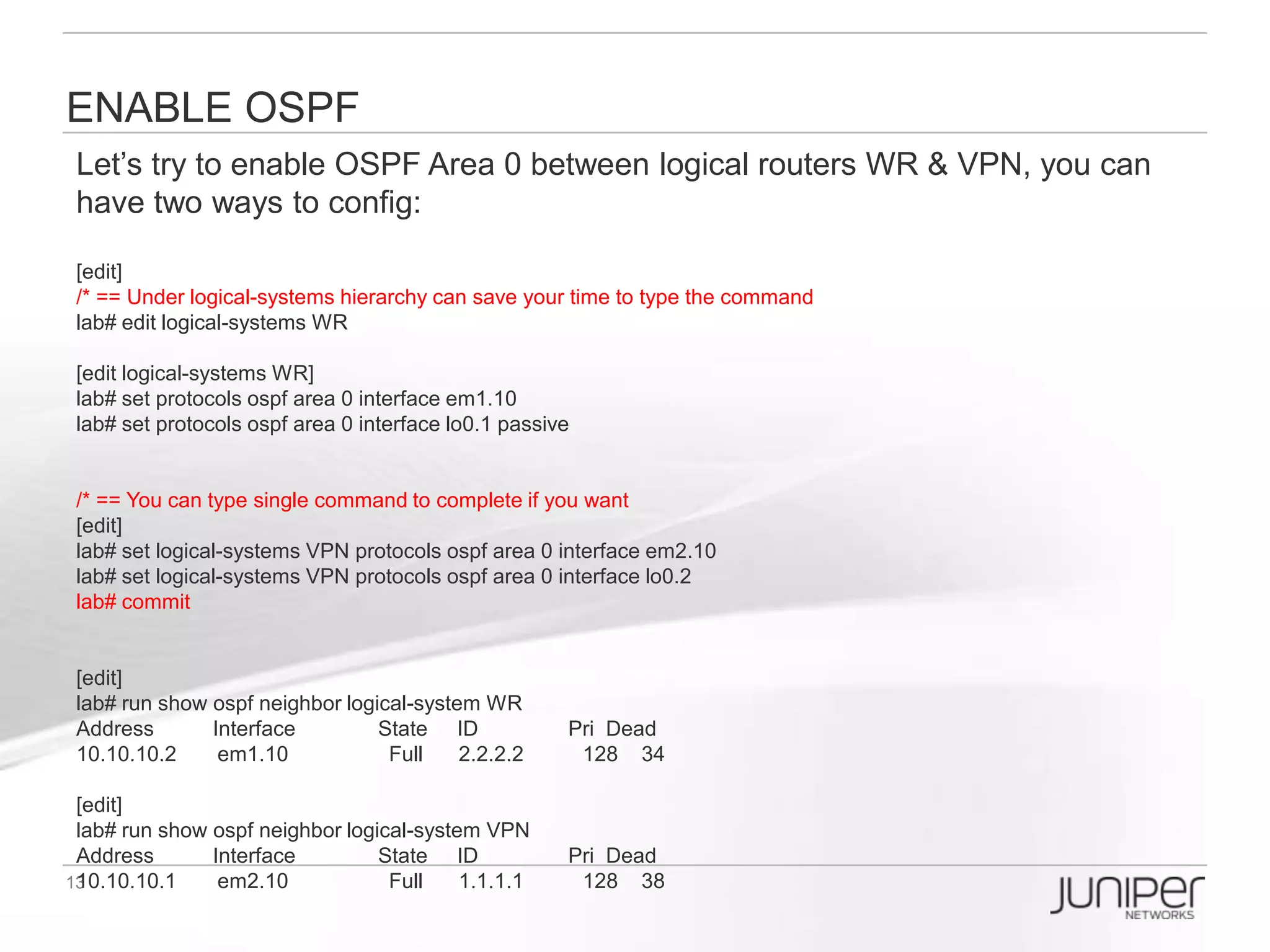
![Enable OSPF
Let’s try to enable OSPF Area 0 between logical routers WR & VPN, you can have
two ways to config:
[edit]
/* == Under logical-systems hierarchy can save your time to type the command
lab# edit logical-systems WR
[edit logical-systems WR]
lab# set protocols ospf area 0 interface em1.10
lab# set protocols ospf area 0 interface lo0.1 passive
/* == You can type single command to complete if you want
[edit]
lab# set logical-systems VPN protocols ospf area 0 interface em2.10
lab# set logical-systems VPN protocols ospf area 0 interface lo0.2
lab# commit
[edit]
lab# run show ospf neighbor logical-system WR
Address Interface State ID Pri Dead
10.10.10.2 em1.10 Full 2.2.2.2 128 34
[edit]
lab# run show ospf neighbor logical-system VPN
Address Interface State ID Pri Dead
10.10.10.1 em2.10 Full 1.1.1.1 128 38](https://image.slidesharecdn.com/olive-120910105545-phpapp01/75/Olive-Introduction-for-TOI-11-2048.jpg)
![Enable BGP
Let’s try to enable BGP in logical router WR:
[edit]
lab# edit logical-systems WR
lab# set routing-options autonomous-system 65001
lab# set protocols bgp group IBGP type internal
lab# set protocols bgp group IBGP neighbor 2.2.2.2 peer-as 65001
lab# set protocols bgp group IBGP neighbor 2.2.2.2 local-address 1.1.1.1
[edit logical-systems WR]
lab# top edit logical-systems VPN
lab# set routing-options autonomous-system 65001
lab# set protocols bgp group IBGP type internal
lab# set protocols bgp group IBGP neighbor 1.1.1.1 peer-as 65001
lab# set protocols bgp group IBGP neighbor 1.1.1.1 local-address 2.2.2.2
lab# commit
[edit]
lab# run show bgp summary logical-system WR
Groups: 1 Peers: 1 Down peers: 0
Table Tot Paths Act Paths Suppressed History Damp State Pending
inet.0 0 0 0 0 0 0
Peer AS InPkt OutPkt OutQ Flaps Last Up/Dwn State|#Active/Received/Accepted/Damped...
2.2.2.2 65001 5 5 0 0 1:13 0/0/0/0 0/0/0/0
[edit]
lab# run show bgp summary logical-system VPN
Groups: 1 Peers: 1 Down peers: 0
Table Tot Paths Act Paths Suppressed History Damp State Pending
inet.0 0 0 0 0 0 0
Peer AS InPkt OutPkt OutQ Flaps Last Up/Dwn State|#Active/Received/Accepted/Damped...
1.1.1.1 65001 4 5 0 0 1:11 0/0/0/0 0/0/0/0](https://image.slidesharecdn.com/olive-120910105545-phpapp01/75/Olive-Introduction-for-TOI-12-2048.jpg)
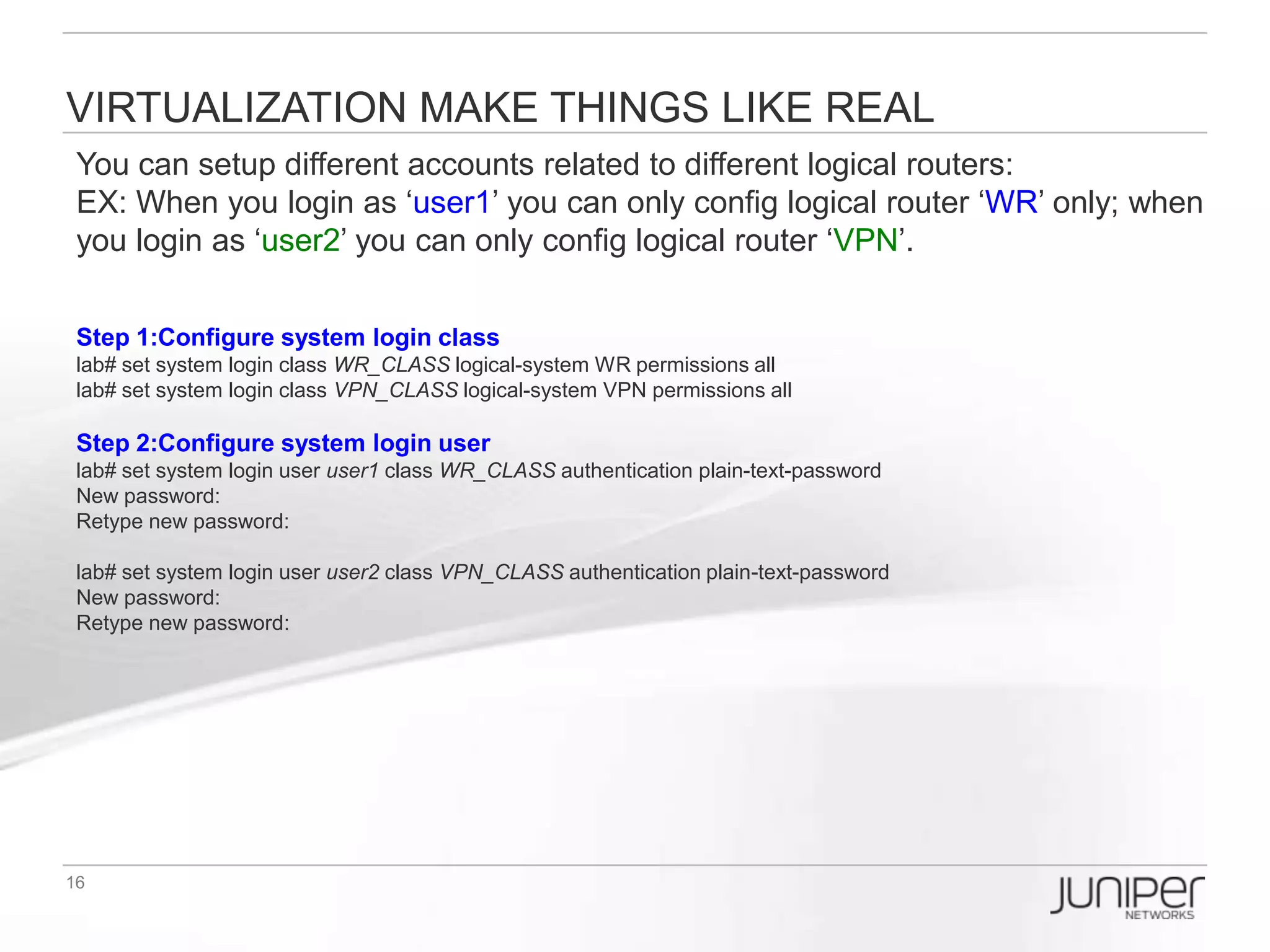
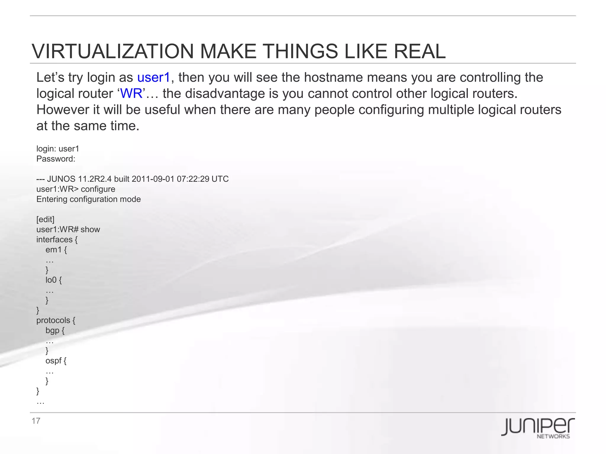
![Virtualization make things like real
Let’s try login as user1, then you will see the hostname means you are controlling
the logical router ‘WR’… the disadvantage is you cannot control other logical
routers. However it will be useful when there are many people configuring multiple
logical routers at the same time.
login: user1
Password:
--- JUNOS 11.2R2.4 built 2011-09-01 07:22:29 UTC
user1:WR> configure
Entering configuration mode
[edit]
user1:WR# show
interfaces {
em1 {
…
}
lo0 {
…
}
}
protocols {
bgp {
…
}
ospf {
…
}
}
…](https://image.slidesharecdn.com/olive-120910105545-phpapp01/75/Olive-Introduction-for-TOI-14-2048.jpg)
![How to apply the pre-config (1/2) ?
[edit]
lab# run file list
/* == olive basic config for interface and management IP access ==*/
baseline.conf
/* == pre-config for EBB topology ==*/
LR_WR_VPN_CS1_CS2.conf
LR_WR_VPN_CS1_CS2_OSPF.conf
LR_WR_VPN_CS1_CS2_BGP.conf
/* == pre-config for R1-R2 (Single AS iBGP) topology ==*/
LR_R1R2.conf
LR_R1R2_OSPF.conf
LR_R1R2_iBGP.conf
LR_R1R2_iBGP_LocalAccount.conf
/* == pre-config for R1-R2, R3-R4 (Multi-AS eBGP) topology ==*/
LR_R1R2R3R4.conf
LR_R1R2R3R4_OSPF.conf
LR_R1R2R3R4_LDP.conf
LR_R1R2R3R4_iBGP_eBGP.conf
LR_R1R2R3R4_iBGP_eBGP_LocalAccount.conf](https://image.slidesharecdn.com/olive-120910105545-phpapp01/75/Olive-Introduction-for-TOI-18-2048.jpg)

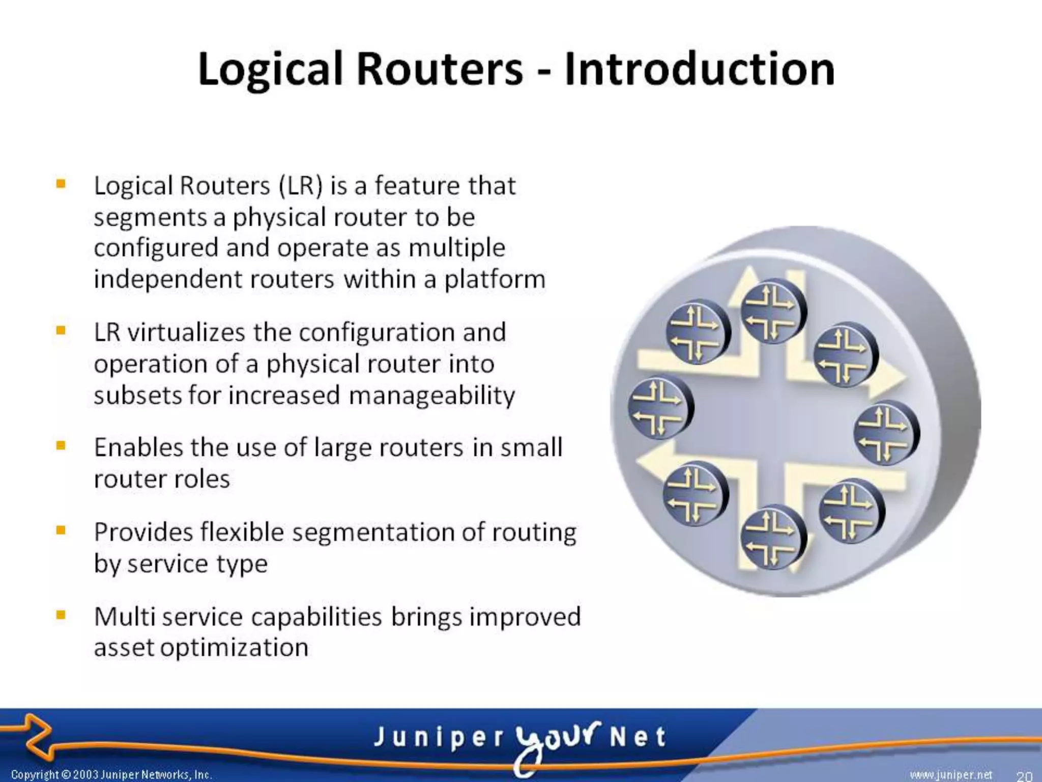
The document discusses Olive, which is the codename for JUNOS software running on a PC rather than a Juniper router. It was originally developed by Juniper as a software development platform before their hardware was fully implemented. The document also discusses logical routers, which allow a single physical router to be partitioned into multiple virtual routers. It provides instructions on configuring logical routers in the Olive VM, including assigning interfaces, enabling OSPF and BGP between the logical routers, and restricting configuration access based on logical router.


![Vibe Coding vs. Spec-Driven Development [Free Meetup]](https://cdn.slidesharecdn.com/ss_thumbnails/vibecodingvsspecdrivendevelopment-251209105622-43f455e7-thumbnail.jpg?width=640&height=640&fit=bounds)

![Coded Agents – with UiPath SDK + LangGraph [Virtual Hands-on Workshop]](https://cdn.slidesharecdn.com/ss_thumbnails/codedagentsdeck-251215155422-5497c599-thumbnail.jpg?width=640&height=640&fit=bounds)
