Downloaded 412 times
![CCNA Exploration
LAN Switching and Wireless: Inter-VLAN Routing Lab 6.4.1: Basic Inter-VLAN Routing
S1(config)#line console 0
S1(config-line)#password cisco
S1(config-line)#login
S1(config-line)#line vty 0 15
S1(config-line)#password cisco
S1(config-line)#login
S1(config-line)#end
%SYS-5-CONFIG_I: Configured from console by console
S1#copy running-config startup-config
Destination filename [startup-config]? [enter]
Building configuration...
Step 2: Re-enable the active user ports on S2 in access mode.
S2(config)#interface fa0/6
S2(config-if)#switchport mode access
S2(config-if)#no shutdown
S2(config-if)#interface fa0/11
S2(config-if)#switchport mode access
S2(config-if)#no shutdown
S2(config-if)#interface fa0/18
S2(config-if)#switchport mode access
S2(config-if)#no shutdown
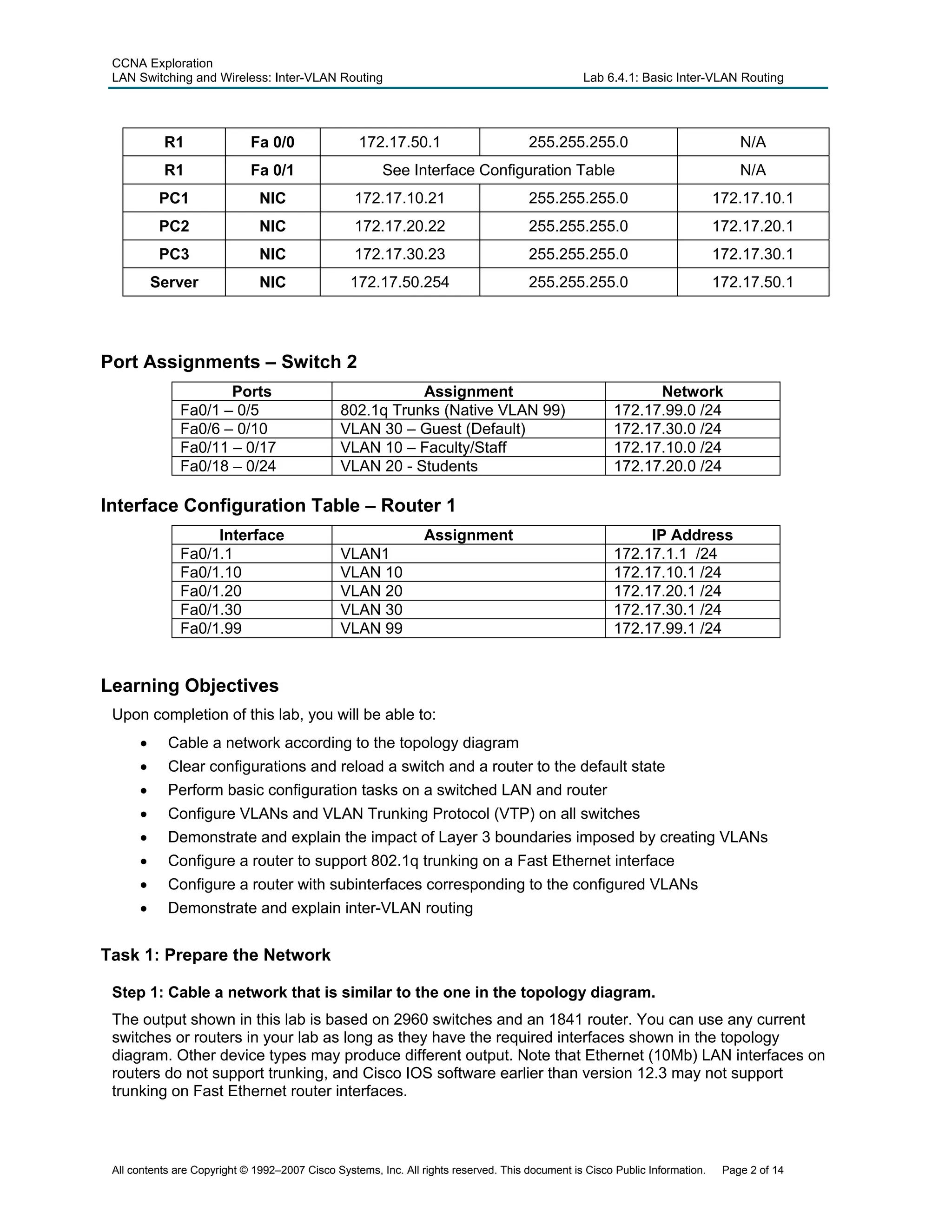
Task 3: Configure the Ethernet Interfaces on the Host PCs
Configure the Ethernet interfaces of PC1, PC2, PC3 and the remote TFTP/Web Server with the IP
addresses from the addressing table.
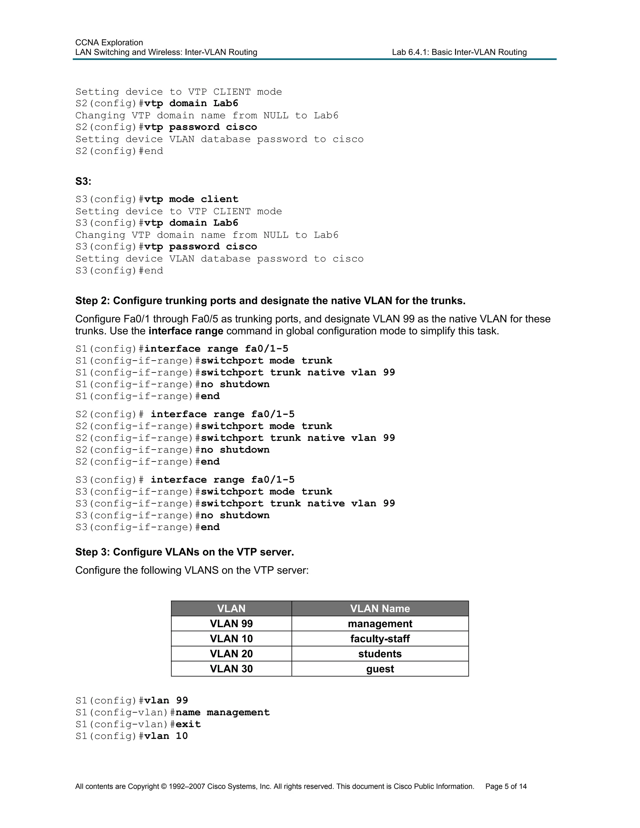
Task 4: Configure VTP on the Switches
Step 1: Configure VTP on the three switches using the following table. Remember that VTP
domain names and passwords are case-sensitive.
Switch Name VTP Operating Mode VTP Domain VTP Password
S1 Server Lab6 cisco
S2 Client Lab6 cisco
S3 Client Lab6 cisco
S1:
S1(config)#vtp mode server
Device mode already VTP SERVER.
S1(config)#vtp domain Lab6
Changing VTP domain name from NULL to Lab6
S1(config)#vtp password cisco
Setting device VLAN database password to cisco
S1(config)#end
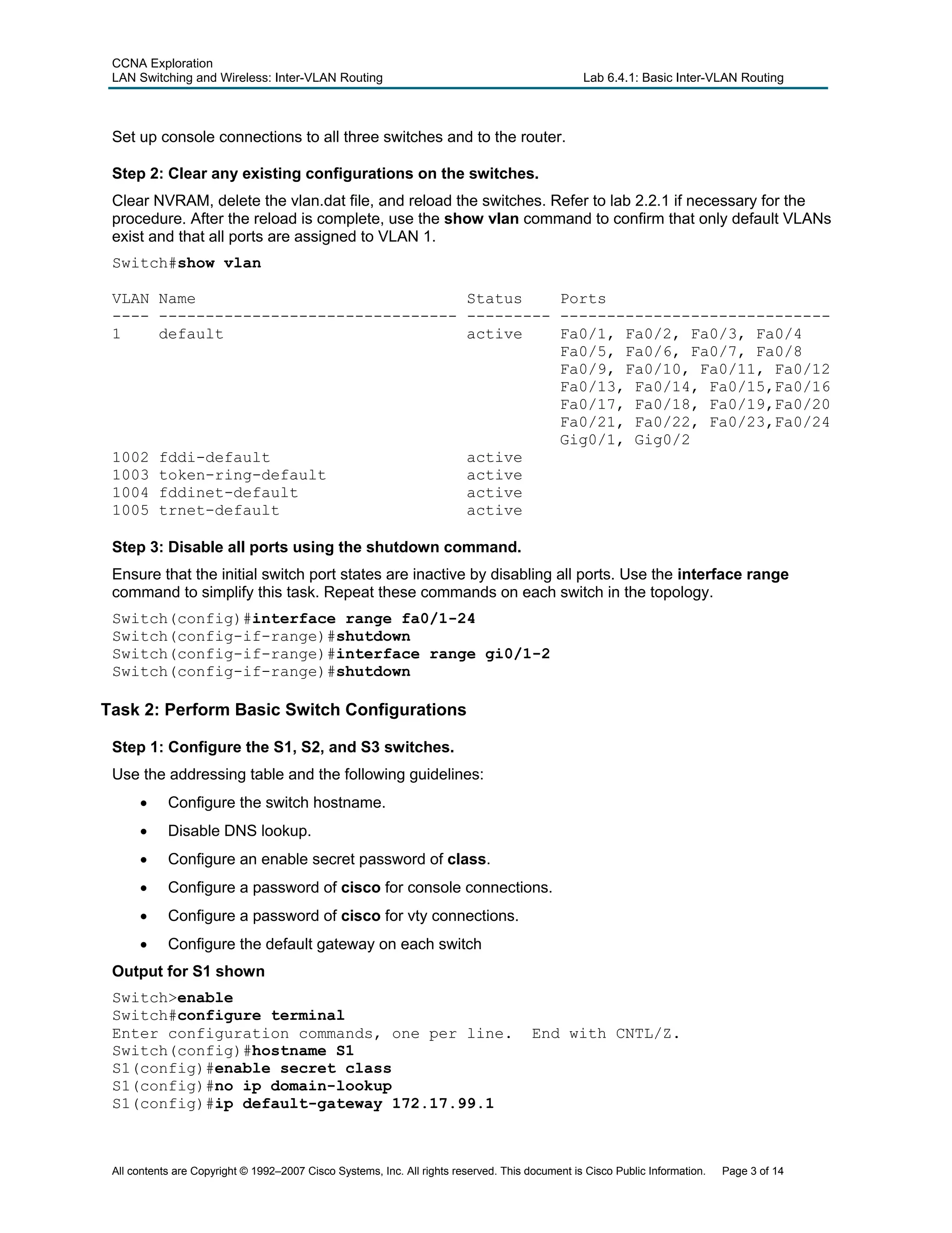
S2:
S2(config)#vtp mode client
All contents are Copyright © 1992–2007 Cisco Systems, Inc. All rights reserved. This document is Cisco Public Information. Page 4 of 14](https://image.slidesharecdn.com/lab6-140707005552-phpapp01/75/Lab6-4-1-4-2048.jpg)
![CCNA Exploration
LAN Switching and Wireless: Inter-VLAN Routing Lab 6.4.1: Basic Inter-VLAN Routing
S2(config)#interface range fa0/6-10
S2(config-if-range)#switchport access vlan 30
S2(config-if-range)#interface range fa0/11-17
S2(config-if-range)#switchport access vlan 10
S2(config-if-range)#interface range fa0/18-24
S2(config-if-range)#switchport access vlan 20
S2(config-if-range)#end
S2#copy running-config startup-config
Destination filename [startup-config]? [enter]
Building configuration...
[OK]
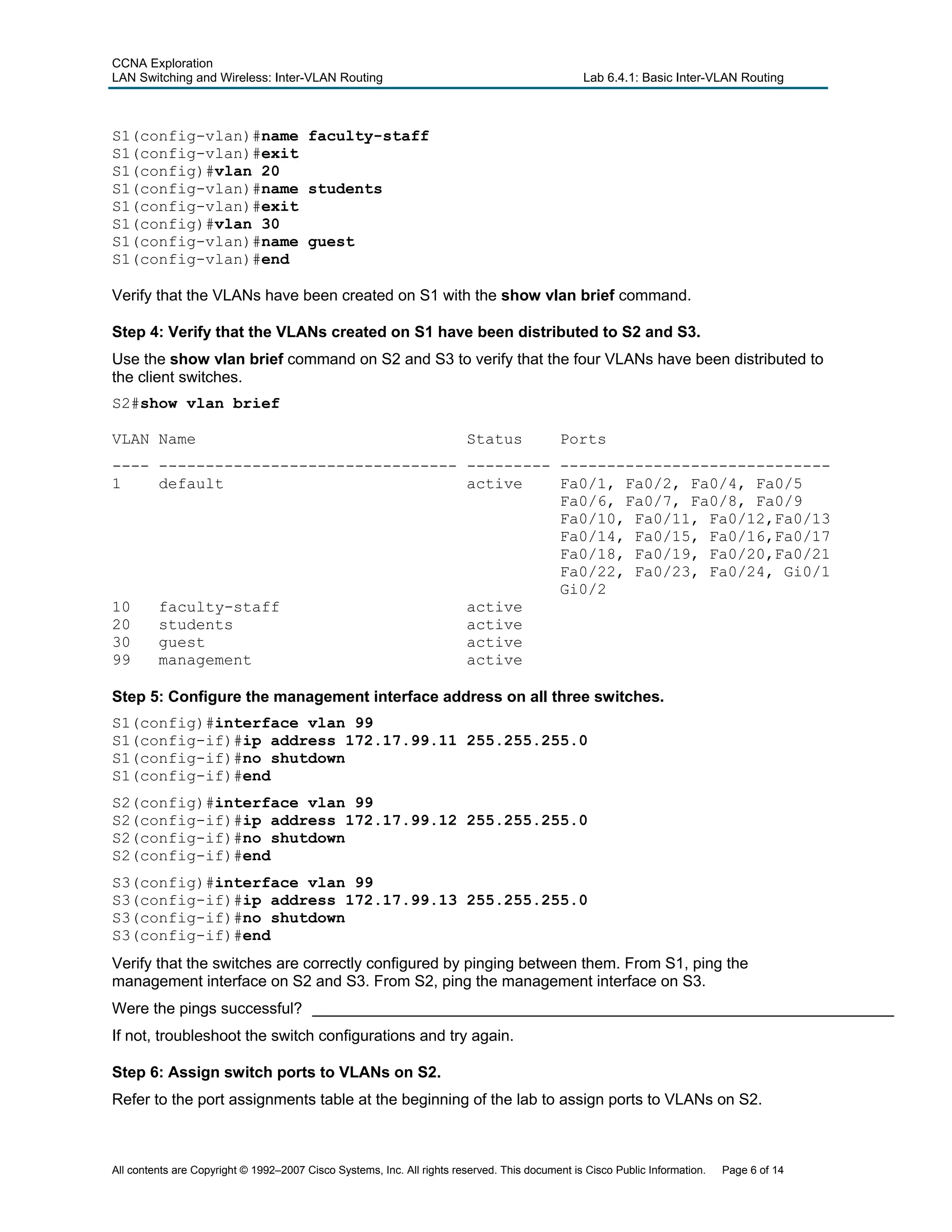
Step 7: Check connectivity between VLANs.
Open command windows on the three hosts connected to S2. Ping from PC1 (172.17.10.21) to PC2
(172.17.20.22). Ping from PC2 to PC3 (172.17.30.23).
Are the pings successful? _____________________________________________________________________
If not, why do these pings fail?__________________________________________________________________
__________________________________________________________________________________________
__________________________________________________________________________________________
Task 5: Configure the Router and the Remote Server LAN
Step 1: Clear the configuration on the router and reload.
Router#erase nvram:
Erasing the nvram filesystem will remove all configuration files! Continue?
[confirm]
Erase of nvram: complete
Router#reload
System configuration has been modified. Save? [yes/no]: no
Step 2: Create a basic configuration on the router.
• Configure the router with hostname R1.
• Disable DNS lookup.
• Configure an EXEC mode password of cisco.
• Configure a password of cisco for console connections.
• Configure a password of cisco for vty connections.
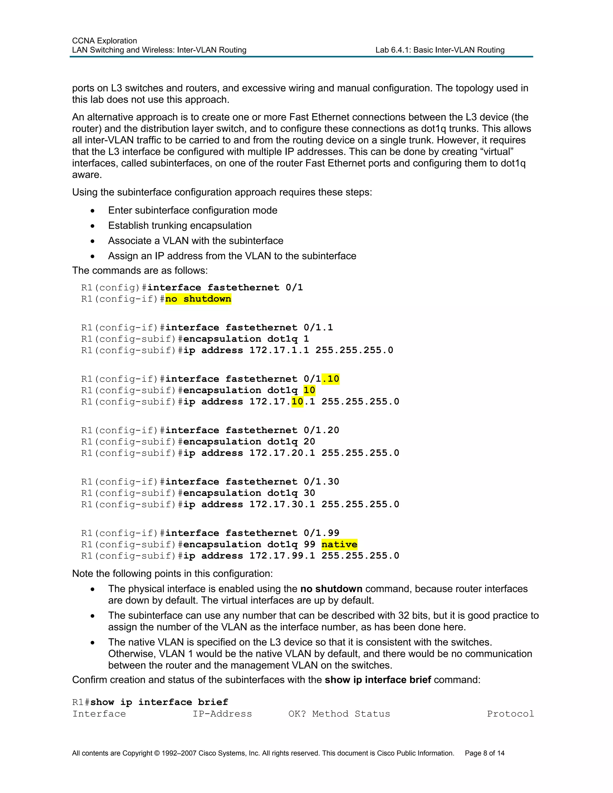
Step 3: Configure the trunking interface on R1.
You have demonstrated that connectivity between VLANs requires routing at the network layer, exactly
like connectivity between any two remote networks. There are a couple of options for configuring routing
between VLANs.
The first is something of a brute force approach. An L3 device, either a router or a Layer 3 capable
switch, is connected to a LAN switch with multiple connections—a separate connection for each VLAN
that requires inter-VLAN connectivity. Each of the switch ports used by the L3 device is configured in a
different VLAN on the switch. After IP addresses are assigned to the interfaces on the L3 device, the
routing table has directly connected routes for all VLANS, and inter-VLAN routing is enabled. The
limitations to this approach are the lack of sufficient Fast Ethernet ports on routers, under-utilization of
All contents are Copyright © 1992–2007 Cisco Systems, Inc. All rights reserved. This document is Cisco Public Information. Page 7 of 14](https://image.slidesharecdn.com/lab6-140707005552-phpapp01/75/Lab6-4-1-7-2048.jpg)
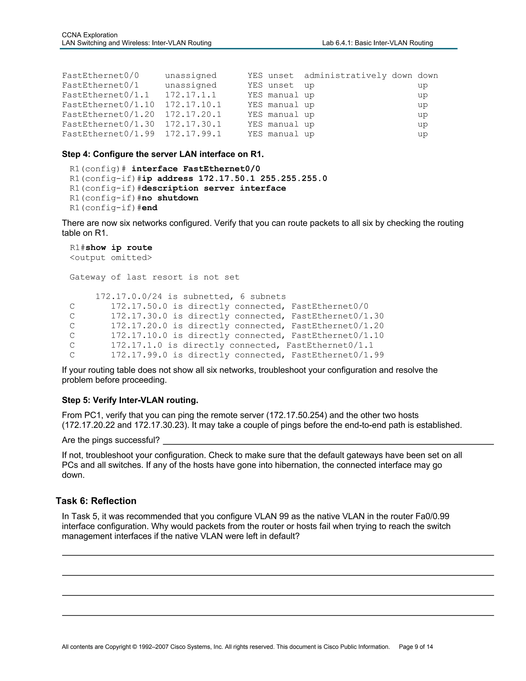

This document provides instructions for configuring basic inter-VLAN routing on a network with three switches and one router. Key steps include: 1. Configuring VTP on the switches with one in server mode and two in client mode to propagate VLANs. 2. Creating VLANs 99, 10, 20 and 30 on the VTP server and assigning ports and IP addresses. 3. Configuring the router interface and subinterfaces for each VLAN to enable inter-VLAN routing. 4. Verifying connectivity between VLANs, which now routes through the router instead of failing.