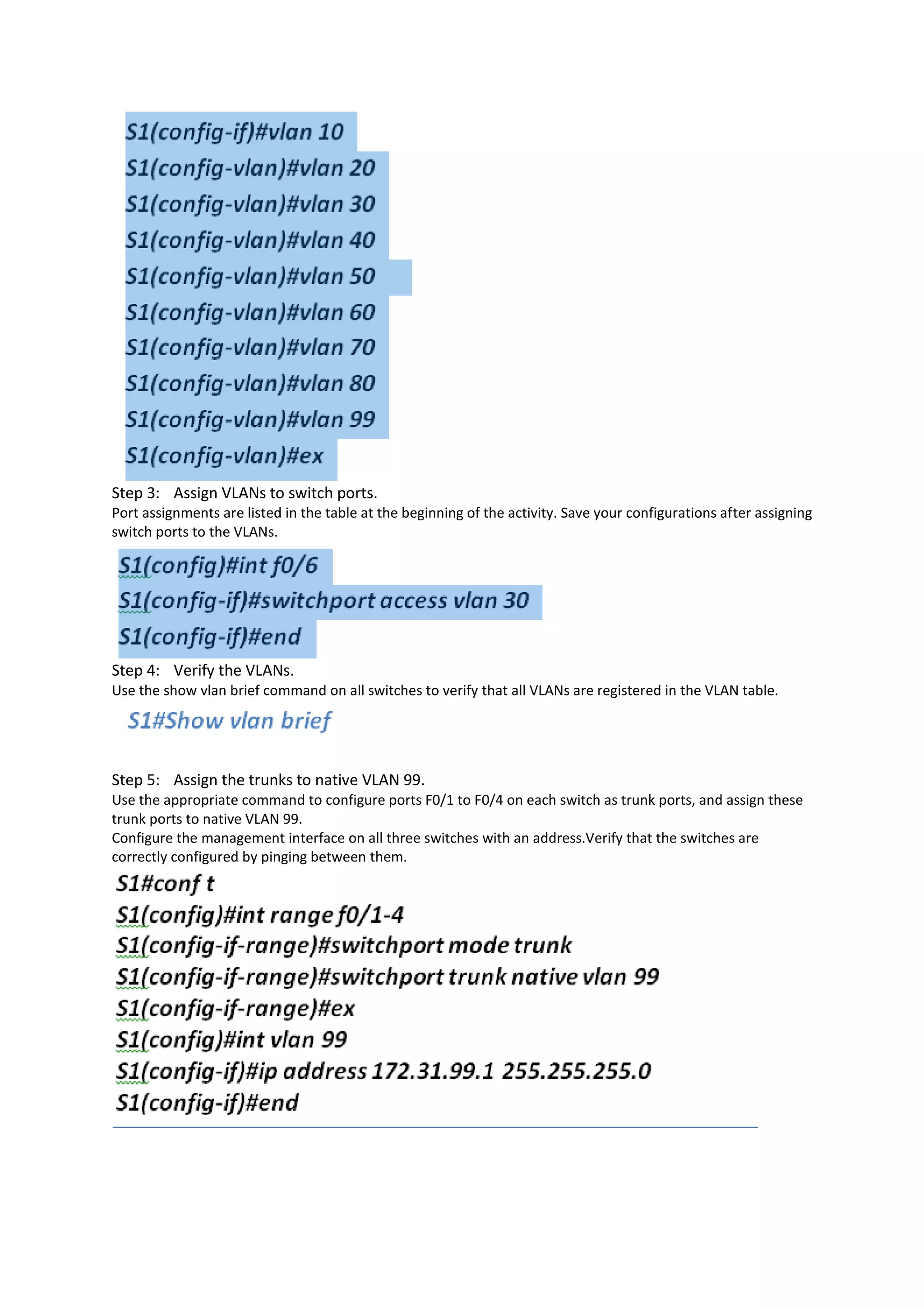
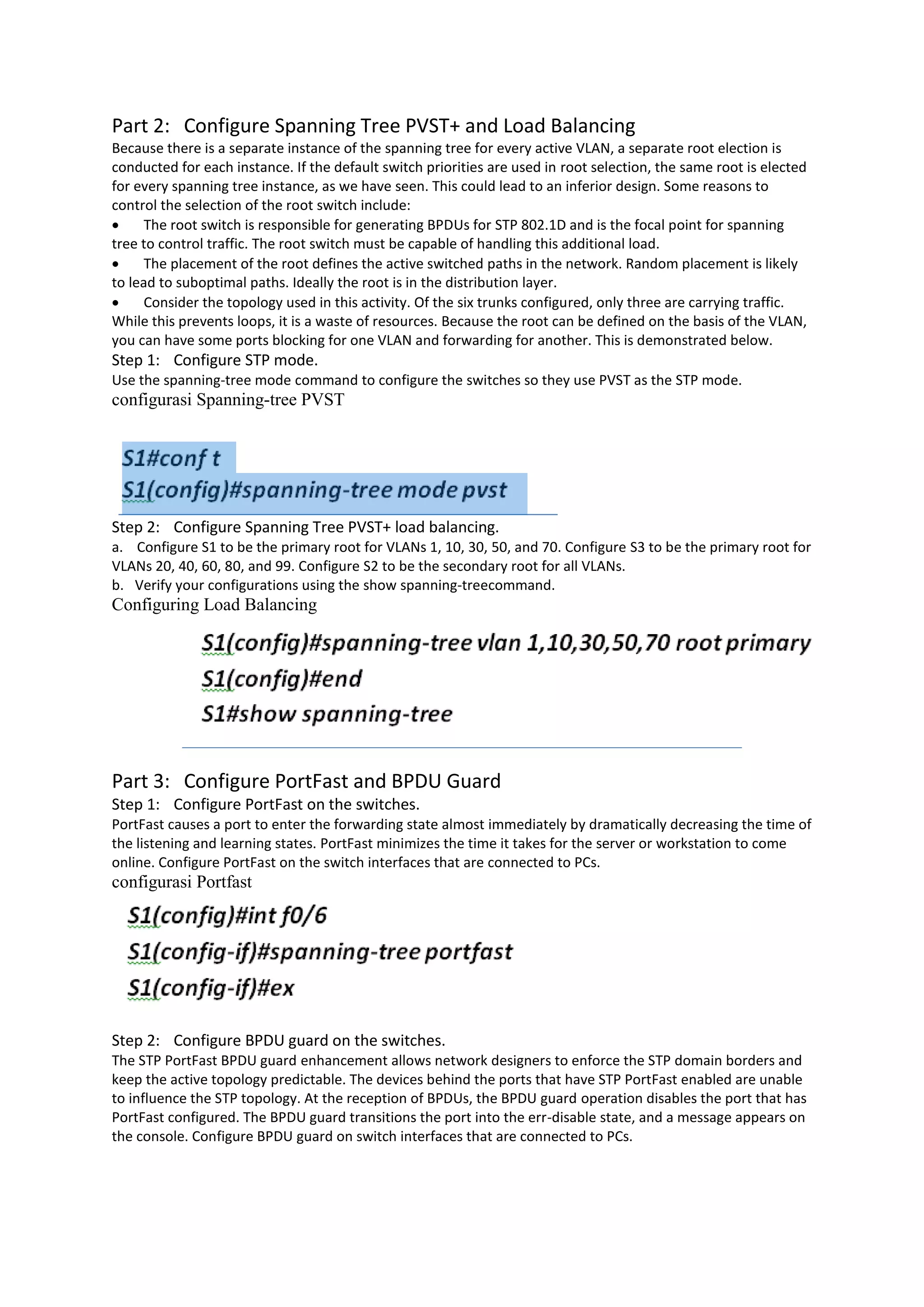
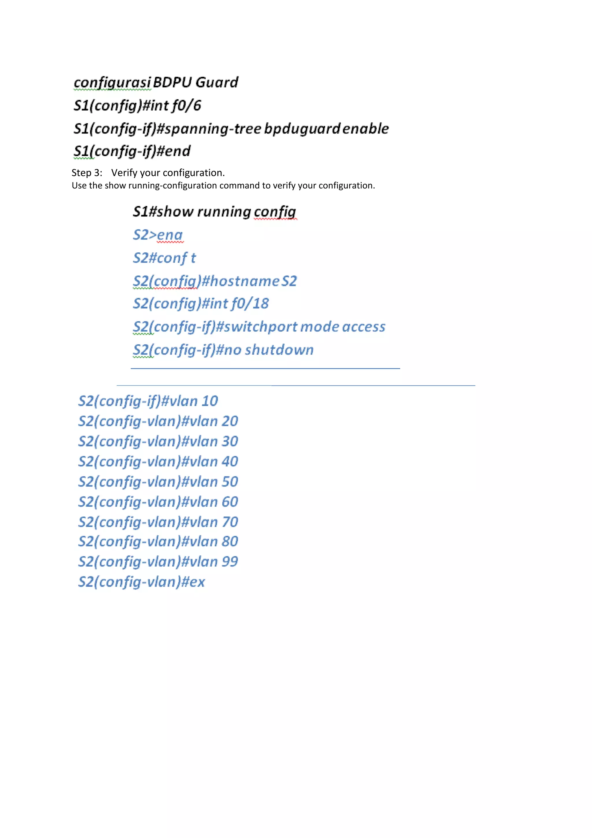
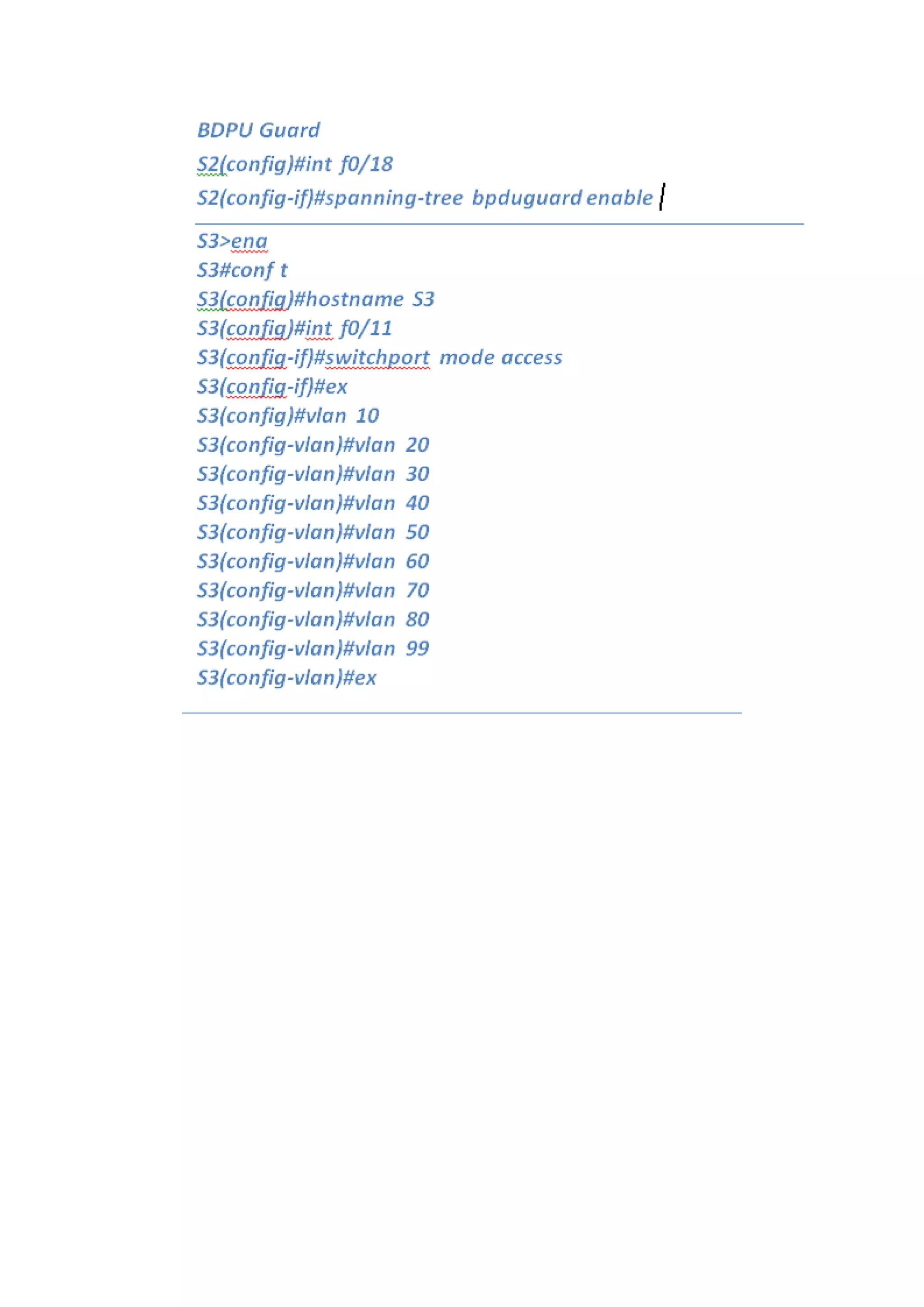
This document describes configuring PVST+ spanning tree protocol on a network topology. It involves:
1. Configuring VLANs, trunk ports between switches, and IP addresses for switch management.
2. Optimizing the spanning tree configuration by making one switch the primary root for certain VLANs and another the secondary root to load balance traffic across trunks.
3. Enabling PortFast on end-user ports to quickly forward traffic and BPDU guard to protect against devices connected to those ports influencing the spanning tree.
1) Describe the three primary options for enabling inter-VLAN routing.
2) Configure legacy inter-VLAN routing.
3) Configure router-on-a-stick inter-VLAN routing.
4) Troubleshoot common inter-VLAN configuration issues.
5) Troubleshoot common IP addressing issues in an inter-VLAN-routed environment.
6) Configure inter-VLAN routing using Layer 3 switching.
7) Troubleshoot inter-VLAN routing in a Layer 3-switched environment.
Difference between Spanning Tree Protocol (STP) and Rapid Spanning Tree
Protocol (RSTP)
1. The main difference between Rapid Spanning Tree Protocol (RSTP IEEE 802.1W) and Spanning
Tree Protocol (STP IEEE 802.1D) is that Rapid Spanning Tree Protocol (RSTP IEEE 802.1W)
assumes the three Spanning Tree Protocol (STP) ports states Listening, Blocking, and Disabled are
same (these states do not forward Ethernet frames and they do not learn MAC addresses).
Hence Rapid Spanning Tree Protocol (RSTP IEEE 802.1W) places them all into a new called
Discarding state. Learning and forwarding ports remain more or less the same.
GLBP (Gateway Load Balancing Protocol) is a Cisco proprietary protocol that attempts to overcome the
limitations of existing redundant router protocols by adding basic load balancing functionality. GLBP is a
virtual gateway protocol similar to HSRP and VRRP.
However, unlike its little brothers, GLBP is capable of using multiple physical gateways at the same time.
As we know, a single HSRP or VRRP group represents one virtual gateway, with single virtual IP and MAC
addresses. Only one physical gateway in a standby/redundancy group is responsible for packet
forwarding, others remain inactive in standby/backup state.
Free CCNP switching workbook by networkershome pdfNetworkershome
ccnp workbook and lab manual by NETWORKERS HOME. NETWORKERS HOME understand the importance of CCNP switching workbook when it comes Cisco certification which is why we offered free CCNP switching workbook.
CCNA DC ,CCNP DC ,CCIE DC ,CCIE DC RACK RENTALS ,CCIE DC LEARNING PPT ,CCIE DC ONLINE TRAINING.
UCS RACK RENTALS ,MDS RACK RENTALS ,NEXUS 7000 RACK RENALS
A
PROJECT REPORT
On
CISCO CERTIFIED NETWORK ASSOCIATE
A computer network, or simply a network, is a collection of computer and other hardware components interconnected by communication channels that allow sharing of resources and information. Where at least one process in one device is able to send/receive data to/from at least one process residing in a remote device, then the two devices are said to be in a network. Simply, more than one computer interconnected through a communication medium for information interchange is called a computer network.
Operation “Blue Star” is the only event in the history of Independent India where the state went into war with its own people. Even after about 40 years it is not clear if it was culmination of states anger over people of the region, a political game of power or start of dictatorial chapter in the democratic setup.
The people of Punjab felt alienated from main stream due to denial of their just demands during a long democratic struggle since independence. As it happen all over the word, it led to militant struggle with great loss of lives of military, police and civilian personnel. Killing of Indira Gandhi and massacre of innocent Sikhs in Delhi and other India cities was also associated with this movement.
This is a presentation by Dada Robert in a Your Skill Boost masterclass organised by the Excellence Foundation for South Sudan (EFSS) on Saturday, the 25th and Sunday, the 26th of May 2024.
He discussed the concept of quality improvement, emphasizing its applicability to various aspects of life, including personal, project, and program improvements. He defined quality as doing the right thing at the right time in the right way to achieve the best possible results and discussed the concept of the "gap" between what we know and what we do, and how this gap represents the areas we need to improve. He explained the scientific approach to quality improvement, which involves systematic performance analysis, testing and learning, and implementing change ideas. He also highlighted the importance of client focus and a team approach to quality improvement.
The French Revolution, which began in 1789, was a period of radical social and political upheaval in France. It marked the decline of absolute monarchies, the rise of secular and democratic republics, and the eventual rise of Napoleon Bonaparte. This revolutionary period is crucial in understanding the transition from feudalism to modernity in Europe.
For more information, visit-www.vavaclasses.com
The Art Pastor's Guide to Sabbath | Steve ThomasonSteve Thomason
What is the purpose of the Sabbath Law in the Torah. It is interesting to compare how the context of the law shifts from Exodus to Deuteronomy. Who gets to rest, and why?
Read| The latest issue of The Challenger is here! We are thrilled to announce that our school paper has qualified for the NATIONAL SCHOOLS PRESS CONFERENCE (NSPC) 2024. Thank you for your unwavering support and trust. Dive into the stories that made us stand out!
Students, digital devices and success - Andreas Schleicher - 27 May 2024..pptxEduSkills OECD
Andreas Schleicher presents at the OECD webinar ‘Digital devices in schools: detrimental distraction or secret to success?’ on 27 May 2024. The presentation was based on findings from PISA 2022 results and the webinar helped launch the PISA in Focus ‘Managing screen time: How to protect and equip students against distraction’ https://www.oecd-ilibrary.org/education/managing-screen-time_7c225af4-en and the OECD Education Policy Perspective ‘Students, digital devices and success’ can be found here - https://oe.cd/il/5yV
How to Make a Field invisible in Odoo 17Celine George
It is possible to hide or invisible some fields in odoo. Commonly using “invisible” attribute in the field definition to invisible the fields. This slide will show how to make a field invisible in odoo 17.
How to Create Map Views in the Odoo 17 ERPCeline George
The map views are useful for providing a geographical representation of data. They allow users to visualize and analyze the data in a more intuitive manner.
Welcome to TechSoup New Member Orientation and Q&A (May 2024).pdfTechSoup
In this webinar you will learn how your organization can access TechSoup's wide variety of product discount and donation programs. From hardware to software, we'll give you a tour of the tools available to help your nonprofit with productivity, collaboration, financial management, donor tracking, security, and more.
How to Split Bills in the Odoo 17 POS ModuleCeline George
Bills have a main role in point of sale procedure. It will help to track sales, handling payments and giving receipts to customers. Bill splitting also has an important role in POS. For example, If some friends come together for dinner and if they want to divide the bill then it is possible by POS bill splitting. This slide will show how to split bills in odoo 17 POS.
1. 2.3.1.5 Packet Tracer Configuration PVST+
Addressing Table
Device Interface IP Address Subnet Mask Default Gateway
S1 VLAN 99 172.31.99.1 255.255.255.0 N/A
S2 VLAN 99 172.31.99.2 255.255.255.0 N/A
S3 VLAN 99 172.31.99.3 255.255.255.0 N/A
PC1 NIC 172.31.10.21 255.255.255.0 172.31.10.254
PC2 NIC 172.31.20.22 255.255.255.0 172.31.20.254
PC3 NIC 172.31.30.23 255.255.255.0 172.31.30.254
Switch Port Assignment Specifications
Ports Assignments Network
S1 F0/6 VLAN 30 172.17.30.0/24
S2 F0/18 VLAN 20 172.17.20.0/24
S3 F0/11 VLAN 10 172.17.10.0/24
Objectives
Part 1: Configure VLANs
Part 2: Configure Spanning Tree PVST+ and Load Balancing
Part 3: Configure PortFast and BPDU Guard
Background
In this activity, you will configure VLANs and trunks, and examine and configure the Spanning Tree Protocol
primary and secondary root bridges. You will also optimize the switched topology using PVST+, PortFast, and
BPDU guard.
Part 1: Configure VLANs
Step 1: Enable the user ports on S1, S2, and S3 in access mode.
Refer to the topology diagram to determine which switch ports (S1, S2, and S3) are activated for end-user
device access. These three ports will be configured for access mode and enabled with the no
shutdown command.
Step 2: Create VLANs.
Using the appropriate command, create VLANs 10, 20, 30, 40, 50, 60, 70, 80, and 99 on all of the switches.
2. Step 3: Assign VLANs to switch ports.
Port assignments are listed in the table at the beginning of the activity. Save your configurations after assigning
switch ports to the VLANs.
Step 4: Verify the VLANs.
Use the show vlan brief command on all switches to verify that all VLANs are registered in the VLAN table.
Step 5: Assign the trunks to native VLAN 99.
Use the appropriate command to configure ports F0/1 to F0/4 on each switch as trunk ports, and assign these
trunk ports to native VLAN 99.
Configure the management interface on all three switches with an address.Verify that the switches are
correctly configured by pinging between them.
3. Part 2: Configure Spanning Tree PVST+ and Load Balancing
Because there is a separate instance of the spanning tree for every active VLAN, a separate root election is
conducted for each instance. If the default switch priorities are used in root selection, the same root is elected
for every spanning tree instance, as we have seen. This could lead to an inferior design. Some reasons to
control the selection of the root switch include:
The root switch is responsible for generating BPDUs for STP 802.1D and is the focal point for spanning
tree to control traffic. The root switch must be capable of handling this additional load.
The placement of the root defines the active switched paths in the network. Random placement is likely
to lead to suboptimal paths. Ideally the root is in the distribution layer.
Consider the topology used in this activity. Of the six trunks configured, only three are carrying traffic.
While this prevents loops, it is a waste of resources. Because the root can be defined on the basis of the VLAN,
you can have some ports blocking for one VLAN and forwarding for another. This is demonstrated below.
Step 1: Configure STP mode.
Use the spanning-tree mode command to configure the switches so they use PVST as the STP mode.
configurasi Spanning-tree PVST
Step 2: Configure Spanning Tree PVST+ load balancing.
a. Configure S1 to be the primary root for VLANs 1, 10, 30, 50, and 70. Configure S3 to be the primary root for
VLANs 20, 40, 60, 80, and 99. Configure S2 to be the secondary root for all VLANs.
b. Verify your configurations using the show spanning-treecommand.
Configuring Load Balancing
Part 3: Configure PortFast and BPDU Guard
Step 1: Configure PortFast on the switches.
PortFast causes a port to enter the forwarding state almost immediately by dramatically decreasing the time of
the listening and learning states. PortFast minimizes the time it takes for the server or workstation to come
online. Configure PortFast on the switch interfaces that are connected to PCs.
configurasi Portfast
Step 2: Configure BPDU guard on the switches.
The STP PortFast BPDU guard enhancement allows network designers to enforce the STP domain borders and
keep the active topology predictable. The devices behind the ports that have STP PortFast enabled are unable
to influence the STP topology. At the reception of BPDUs, the BPDU guard operation disables the port that has
PortFast configured. The BPDU guard transitions the port into the err-disable state, and a message appears on
the console. Configure BPDU guard on switch interfaces that are connected to PCs.
4. Step 3: Verify your configuration.
Use the show running-configuration command to verify your configuration.