Download as PDF, PPTX


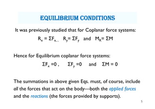
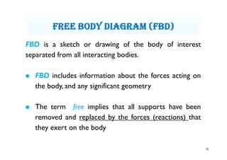


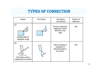
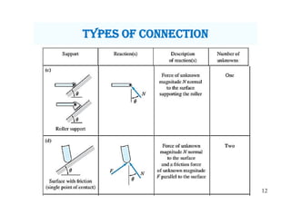


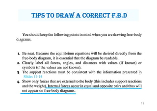
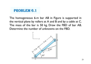


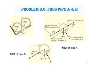
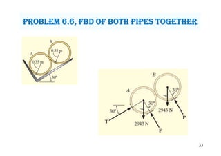

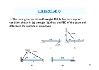


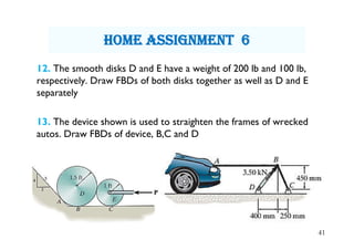

This document discusses equilibrium of coplanar force systems and free body diagrams (FBD). It contains 13 lecture slides that cover the following key points: - How to determine if a system of forces is in equilibrium. - The three conditions for equilibrium of coplanar force systems. - How to construct an FBD by removing supports and drawing all applied and reaction forces. - Examples of different support types and how they influence reaction forces. - Step-by-step instructions and examples for drawing FBDs of various structures and systems. - 13 practice problems for drawing FBDs are assigned as homework.


![Module 14 [Compatibility Mode].pdf](https://cdn.slidesharecdn.com/ss_thumbnails/module14compatibilitymode-221005020212-a4e2d1ee-thumbnail.jpg?width=640&height=640&fit=bounds)