SlideShare a Scribd company logo
15-Mar-13
CE 370: Prof. A. Charif 1
CE 370
REINFORCED CONCRETE-I
Prof. A. Charif
Shear in RC Beams
Shear in Beams
2
• Transverse loads on
beams cause
bending moment M
and shear force V
• Shear force V is the
first derivative of
the moment M
dx
dM
V 
15-Mar-13
CE 370: Prof. A. Charif 2
Shear in Beams
3
• Bending moment causes normal stresses with compression
resisted by concrete and tension by longitudinal steel bars
• Bending design delivers required longitudinal steel
• Shear force causes shear stress and shear design is performed
independently
• Shear failure is brittle and
dangerous
• Shear design must deliver a
shear strength equal to or
greater than flexural strength
• Shear is resisted by concrete
and steel stirrups
Shear stress in an uncracked section
4
Ib
VQ
v
I
My
f 
• Flexural stress is horizontal (compression in top, tension in bot.)
• Shear stress has equal vertical and horizontal components
• This leads to inclined principal stresses (normal stress, no shear)
beamofWidth
fiberaboveareaofmomentFirst
inertiaofMomentforceShear



b
Q
IV
15-Mar-13
CE 370: Prof. A. Charif 3
5
f
v
v
ff
fp
2
tan2
22
2
2








principal stresses
• The two normal principal stresses (one is tension and other is
compression) are inclined and this angle is 450 at the neutral
axis level (f = 0)
• The inclination angle changes in top (compression side) and
bottom (tension side) regions
6
Shear stress and inclined cracking
• Principal stress
trajectories are flat at
top (compression zone)
and deep at bottom
(tension zone)
• Inclined cracks are due
to combined flexure
and shear
• Diagonal tension in
tension side must be
resisted by adequate
web reinforcement
15-Mar-13
CE 370: Prof. A. Charif 4
Average Shear Stress between Cracks
7
jdb
V
v
xb
T
v
jd
xV
jd
M
T
jd
M
T
ww







 isstressshearAverage
db
V
v
w

:ACI/SBC
Average
shear stress
must not
exceed
certain limit
Modes of Shear Failure
in Normal Beams
• Shear behavior and analysis of RC beams is quite complex.
• Several experimental studies have been conducted to identify
the various modes of failure due to combined shear and
bending
• Shear behavior and failure is closely related to shear span to
depth ratio a /d
• For normal beams, shear failure modes are :
 Diagonal tension failure
 Flexural shear failure
 Diagonal compression failure
8
15-Mar-13
CE 370: Prof. A. Charif 5
Diagonal tension Failure
(Web-shear cracks)
• Web shear cracks occur around neutral axis under large shear force
and small bending moment. These cracks are normally at 450 with
the horizontal and form near the mid-depth of sections and move
on a diagonal path to the tension surface.
• Occur at ends of beams at simple supports and at inflection points
in continuous beams
9
Flexural-shear Failure
(Flexure-shear cracks)
• For flexure-shear cracks to occur, the moment must be larger
than the cracking moment and the shear must be rather large.
• The cracks run at angles of about 450 with the beam axis and
often start at the top of the flexural cracks.
10
15-Mar-13
CE 370: Prof. A. Charif 6
Diagonal compression failure
• Diagonal compression failure occurs under large
shear force. It is characterized by the crushing of
concrete. Normally it occurs in beams which are
reinforced against heavy shear.
11
12
Modes of Shear Failure
in Short and Deep Beams
15-Mar-13
CE 370: Prof. A. Charif 7
Forces in a cracked beam
without stirrups
• Shear strength mechanism of RC members includes :
– Concrete compression force in uncracked region
– Aggregate interlocking in cracked zone
– Shear across longitudinal steel bars known as dowel force
– Shear reinforcement, if present, will also resist the shear force
13
14
Forces in a beam with vertical stirrups
15-Mar-13
CE 370: Prof. A. Charif 8
15
Types of Shear Reinforcement (Stirrups)
• Steel stirrups may be inclined along diagonal tension but are
usually vertical
• Part of longitudinal bars may also be bent up from bottom to top
to play role of shear reinforcement and then top steel
• Nowadays,
stirrups are
often vertical
16
Types of Shear Reinforcement
• Inclined stirrups and bent up bars are not very practical
because of the high labor costs for positioning them.
• Nowadays, stirrups are often vertical
Bent up bars
15-Mar-13
CE 370: Prof. A. Charif 9
17
Types of Shear Reinforcement (Stirrups)
Behavior of RC beams with web
reinforcement (Truss Analogy)
 Concrete in compression is top chord
 Longitudinal tension steel is bottom chord
 Stirrups form truss verticals
 Concrete between diagonal cracks form the truss diagonals
18
15-Mar-13
CE 370: Prof. A. Charif 10
Shear Stress Transfer in RC Beams
• Diagonal cracks will occur in beams with shear reinforcement
at almost the same loads that they occur in beams of the same
size without shear reinforcement.
• The shear reinforcement makes its presence known only after
the cracks begin to form. At that time, beams must have
sufficient shear reinforcing to resist the shear force not resisted
by the concrete.
• After a shear crack has developed in a beam, only a little shear
can be transferred across the crack unless web reinforcing is
used to bridge the gap. When such reinforcing is present, it
keeps the pieces of concrete on the two sides of the crack from
separating.
19
Benefits of Stirrups
 Stirrups carry shear across the crack directly
 Promote aggregate interlock
 Confine the core of the concrete in the beam thereby
increasing strength and ductility
 Confine the longitudinal bars and prevent concrete
cover from splitting off the beam
 Hold the pieces of concrete on either side of the
crack together and prevent the crack from
propagating into the compression region
20
15-Mar-13
CE 370: Prof. A. Charif 11
CE 370
REINFORCED CONCRETE-I
Prof. A. Charif
Shear analysis and design of RC beams
according to SBC / ACI Codes
• SBC, ACI and other codes neglect aggregate interlock and
dowel action
• Shear force is resisted by compression concrete and by steel
stirrups only
• Nominal shear strength is therefore:
22
strengthshearStirrups:
strengthshearConcrete:
s
c
scn
V
V
VVV 
Steel stirrups may be inclined along diagonal tension but are
usually vertical
Shear Analysis and Design
according to SBC / ACI Codes
15-Mar-13
CE 370: Prof. A. Charif 12
Shear Analysis and Design
according to SBC / ACI Codes
23
shearin0.75With
strengthshearStirrups:
strengthshearConcrete:
with




s
c
scnun
V
V
VVVVV
Nominal shear strength is provided by concrete and stirrups only
Design shear strength must be equal to or greater than ultimate shear
• Concrete may provide enough strength to resist ultimate shear
but SBC / ACI require stirrups if:
222
c
u
cuc
n
V
V
VVV
V



Shear Analysis and Design
according to SBC / ACI Codes
24
scnun VVVVV  with
• SBC / ACI nominal shear
strength of concrete in beams is : db
f
V w
'
c
c
6

• For axially loaded members (columns) the nominal shear
strength of concrete is :
db
f
A
N
VN
db
f
A
N
VN
w
'
c
g
u
cu
w
'
c
g
u
cu
6
3.0
1:0)(Tension
614
1:0)(nCompressio


















15-Mar-13
CE 370: Prof. A. Charif 13
25
Shear Analysis and Design per SBC / ACI
 
areasection-crossStirrup:
cossin:stirrupsInclined
:stirrupsVertical
v
yvs
yv
yvss
A
s
d
fAV
s
dfA
fAnV
 

• Assuming a 450 inclined crack,
the number of vertical stirrups
crossed by the crack is ns = d/s
where s is the stirrup spacing
• Assuming that they have yielded
the stirrups shear strength is :
Stirrup Section Area
• A stirrup has at least one leg but usually two legs or more.
26
diameterStirrup:
4
:legswithStirrup
2
s
s
v
yv
s
d
d
nA
n
s
dfA
V


15-Mar-13
CE 370: Prof. A. Charif 14
Section Adequacy for Shear
• Before performing design, the section must first be checked
whether it is sufficient to resist shear according to SBC / ACI.
• The section is insufficient to resist shear and must be increased if :
27
6
5:ifshearforsectionntInsufficie
:isconditionthestress,shearaverageofIn terms
5:ifshearforsectionntInsufficie
6
but
3
2
3
2 ''
'
c
w
u
u
cu
w
'
c
c
wcc
u
wcs
f
db
V
v
VV
db
f
V
dbfV
V
dbfV







Beam Shear Design
Required Vertical Stirrup Spacing
28
 
trequiremensteelminimumUse0if:Note
:spacingstirrupRequired
designOptimalwith











c
u
s
c
u
yv
c
uyv
c
u
susc
unscnun
V
V
V
V
V
dfA
s
V
V
s
dfA
V
V
VVVV
VVVVVVV





22
c
u
c
n
V
V
V
V


• SBC / ACI specify that stirrups are required in beams if :
15-Mar-13
CE 370: Prof. A. Charif 15
Minimum Web Reinforcement
and Maximum Stirrup Spacing
SBC / ACI minimum web steel area :
29
y
wc
v
f
sbf
A









3
1
,
16
Max
'
min,
 
 
 
 










(b)Case300,25.0Min3If
(a)Case600,5.0Min3If
(b)Case300,25.0Min2If
(a)Case600,5.0Min2If
max
max
max
max
mmdsVV
mmdsVV
mmdsVV
mmdsVV
cu
cu
cs
cs


SBC / ACI maximum stirrup spacing (geometry considerations) :
Critical Shear Sections
• Load transfer between beams and supports is performed through
conic shaped zones with 450 angles.
• Shear failures occur at critical sections located at a distance d from
the face of the support, where d is the depth of tension steel
• Ultimate shear force considered for design is computed at the
critical section
30
15-Mar-13
CE 370: Prof. A. Charif 16
31
Critical Shear Sections
Critical Shear Section for Design
• Ultimate shear used for design is computed at the critical section
at a distance d from the support face (d = Tension steel depth)
• It is obtained from support and mid-span values using shear force
envelope diagram.
• Most modern structural analysis methods use clear length Ln (clear
distance between support faces)
32
nL
Stirrup reinforcement in beams
is usually symmetric about
mid-point except in special
cases such as cantileversLn/2d
VuL/2
Vud
Vu0
15-Mar-13
CE 370: Prof. A. Charif 17
Critical Shear Section for Design
• For a simply supported beam, the ultimate shear force values at
the support and mid-span are :
33
82
2/0
nLu
uL
nu
u
Lw
V
Lw
V 
wu : Total factored (ultimate) uniform load (= 1.4wD + 1.7wL)
wLu : Factored live load (= 1.7wL)
Shear force at support is obtained with ultimate uniform load
applied on all the span
The mid-span value is obtained by applying factored live load on
half the span only (along with factored dead load on all span).
Ln/2d
VuL/2
Vud
Vu0
Critical Shear Section for Design
34
Ln/2d
VuL/2
Vud
Vu0
From similar triangles we obtain the
critical shear value at distance d :
 
8
,
2
with
2
2/0
2/00
nLu
uL
nu
u
uLu
n
uud
Lw
V
Lw
V
VV
L
d
VV


L
1w
2w
SFD82
21
L
w
L
w 
8
2
L
w







8
3
2
21
L
w
L
w
Mid-span shear value
15-Mar-13
CE 370: Prof. A. Charif 18
Shear Design - Summary
1. Determine ultimate shear force at distance d from support face,
to be used for design
2. Compute concrete shear strength Vc
3. Check for section adequacy (whether it is sufficient for shear).
If insufficient, the section must be increased.
4. Check whether stirrups are required
5. Compute maximum stirrup spacing
6. Compute minimum shear steel area
7. Compute required stirrup spacing
8. Select appropriate stirrup diameter and spacing to satisfy all
conditions (maximum spacing, minimum shear steel, required
spacing)
35
36
Shear Design - Summary
 
 
 
y
wc
v
cu
cu
c
u
cu
w
'
c
c
nLu
uL
nu
uuLu
n
uudu
f
sbf
A
mmdsVV
mmdsVV
V
V
VV
db
f
V
Lw
V
Lw
VVV
L
d
VVV


















3
1
,
16
MaxareasteelshearMinimum/6
(b)300,25.0Min3If
(a)600,5.0Min3If
:spacingstirrupMaximum/5
2
ifrequiredareStirrups/4
5ifshearforsectionntInsufficie/3
6
/2
8
,
2
with
2
/1
'
min,
max
max
2/02/00




15-Mar-13
CE 370: Prof. A. Charif 19
37
Shear Design – Summary Cont.
7step-spacingstirrupRequiredc/
6step-areasteelshearMinimumb/
5step-spacinggeometryMaximuma/
:conditionsthreeesatisfy thorder toinspacingstirrup
andlegsofnumberdiameter,stirrupeappropriatSelect/8
discardedisspacingrequiredthen,0if:Note
spacingstirrupRequired/7



c
u
s
c
u
yv
V
V
V
V
V
dfA
s


• In practice the stirrup diameter ds is usually fixed and the
designer must determine the required number of legs and spacing.
• ds depends on the diameter of the main bars
• In buildings, ds is 10 mm for columns, 8 to10 mm for beams
• In bridges ds is higher (12 to 16 mm)
38
Shear Design – Summary Cont.
The three SBC / ACI requirements (steps 5 to 7) can be reformulated
using the stirrup spacing as the main design variable.
The designer usually selects first the stirrup diameter ds, the number of
legs n, and then determines the required stirrup spacing s, while
satisfying all code requirements. Given its diameter ds and the number
of legs n, the stirrup area is:
4
2
s
v
dn
A


The minimum shear steel area requirement, expressed in terms of
spacing s, can thus be transformed to another spacing requirement:
w
yv
c
y
wc
v
b
fA
f
s
f
sbf
A


















0.3,
0.16
MinspacingsteelMaximum
3
1
,
16
MaxareasteelshearMinimum
'
2
max
'
min,
15-Mar-13
CE 370: Prof. A. Charif 20
39
Shear Design - Stirrup Spacing Summary
 
 
 
(b)byorbycontrolledisitifincreasedbeonlycanSpacing
(b)casebycontrolledisitunlessunchangedremains
decreases.whenincreases.shearultimateondependsOnly
notdoesbut)and(onondependand:Notes
,,Min:spacingAdopted
:spacingstirrupRequired
0.3,
0.16
Min:spacingsteelMinimum
(b)3If300,25.0Min
(a)3If600,5.0Min
:spacingGeometry
1
max
3
max
1
max
3
max
3
max
1
max
3
max
2
max
3
max
2
max
1
max
3
max
'
2
max
1
max
ss
s
VsVs
sdnAss
ssss
V
V
dfA
s
b
fA
f
s
VVmmd
VVmmd
s
uu
sv
c
u
yv
w
yv
c
cu
cu






















40
Shear design
and spacing
c
u
yv
w
yv
c
cu
cu
V
V
dfA
s
b
fA
f
s
mm
d
sVV
mm
d
sVV



































3
max
'
2
max
1
max
1
max
0.3,
0.16
Min
300,
4
Min:3
600,
2
Min:3
(b)
(a)
Vu
cV5.0
cV3
cV
cV5
requiredstirrupsNo
3
maxs
(a)Case1
max s
2
(a)Case
(b)Case1
max s
sectionntInsufficie
15-Mar-13
CE 370: Prof. A. Charif 21
41
?5 cu VV  dimensionsIncrease
sectionntInsufficie
?5.0 cu VV  requirednotStirrups
?3 cu VV  (b)300,
4
Min1
max 





 mm
d
s(a)600,
2
Min1
max 





 mm
d
s
w
yv
c
b
fA
f
s








 0.3,
0.16
Min
'
2
max
?cu VV 
 2
max
1
max ,Min sss 
c
u
yv
V
V
dfA
s



3
max
 3
max
2
max
1
max ,,Min ssss 
Yes
No
Yes
Yes
Yes
No
No
No
db
f
V
V
w
'
c
c
u
6
75.0,known


Shear design Flowchart
Shear Design - Observations
• The designed stirrup spacing may turn out inadequate in many
ways. It could be either too large or too small.
• If the spacing is too large, then the number of legs or (and) stirrup
diameter may be decreased.
• If the spacing is too small, then either the number of legs or
stirrup diameter must be increased.
• A complete and adequate design strategy is to start using the
minimum stirrup diameter and minimum number of legs.
• If the spacing is too small (less than 100 mm), increase the
number of legs, but if the number of legs is excessive then
increase the stirrup diameter.
42
15-Mar-13
CE 370: Prof. A. Charif 22
Shear Design - Full Automatic Algorithm
Data includes minimum stirrup diameter dsmin as well as minimum
and maximum numbers of legs nmin and nmax
Leg increment = 1 , Stirrup diameter increment = 2 mm
• Compute s1
max
• Start with dsmin
• A - Start with nmin
• B - Compute stirrup area
• Compute s2
max , s3
max and final spacing value
• If spacing value is ok stop
• If spacing too small then :
 If n < nmax : n = n + 1 and goto B
 If n = nmax : ds = ds + 2.0 and goto A
43
Stirrup Design Algorithm
(Stirrup Diameter, Number of Legs and Spacing)
1. Compute maximum geometry spacing s1
max
2. Start with minimum stirrup diameter dsmin
3. Start with minimum leg number nmin
4. Compute stirrup area
5. Compute minimum steel spacing s2
max
6. If Vu > Vc : s = Min (s1
max , s2
max)
7. If Vu ≤ Vc : Compute required steel spacing s3
max and
s = Min (s1
max , s2
max , s3
max)
8. If s ≥ 100 mm then stop
9. If n < nmax then n = n + 1 and goto 4
10. If n = nmax then ds = ds + 2 and goto
44
15-Mar-13
CE 370: Prof. A. Charif 23
Shear Design Problem 1
• A simply supported beam is subjected to uniform
loading composed of dead load (including self weight)
of 27.0 kN/m and live load of 17.5 kN/m.
• The beam clear span length is 9.6 m and the section
dimensions are 300 x 600 mm.
• Steel depth is d = 540 mm
• Design the beam for shear using 10 mm stirrups and the
following material data :
45
MPafMPaf yc 42025'

Solution 1
The ultimate load is :
wu = 1.4 x 27.0 + 1.7 x 17.5 = 37.8 + 29.75 = 67.55 kN/m
Factored live load is : wLu = 1.7 x 17.5 = 29.75 kN/m
Ultimate shear force at support and mid-span as well as value at the
critical section (at a distance d from the support) are:
46
 
  kNV
VV
L
d
VV
kN
L
wV
kN
L
wV
ud
uLu
n
uud
n
LuuL
n
uu
78.2917.3524.324
6.9
54.02
24.324
2
7.35
8
6.9
75.29
8
24.324
2
6.9
55.67
2
2/00
2/
0






15-Mar-13
CE 370: Prof. A. Charif 24
47
Solution 1 – Cont.
designforusedis
78.291
7.35
24.324
62.505.0
2/
0
ud
ud
uL
u
c
V
kNV
kNV
kNV
kNV




Ln/2 = 4.8 m0.54m
VuL/2
Vud
Vu0
cV5.0
Concrete nominal shear strength is :
kNNdb
f
V w
c
c 0.135135000540300
6
25
6
'

2
22
6.235
4
103
4
3:stirrupsleg3Use
requiredareStirrups625.5050.:trequiremenStirrup
OKSection78.29125.50613575.055
:checkadequacySection
mm
dn
An
VkNV
kNVVkNV
s
v
udc
uduc






Solution 1 – Cont.
48
  (a)Case0.270600,5.0Min
75.303378.291:spacinggeometryMaximum
1
max mmmmds
kNVV cud

 
mms
b
fA
f
s
w
yv
c
5.989
300
4206.235
0.3,
25
0.16
Min
0.3,
0.16
Min:spacingsteelMinimum
2
max
'
2
max


















mms
V
V
dfA
s
c
ud
yv
3.210
10000.135
75.0
78.291
5404206.235
:spacingstirrupRequired
3
max
3
max













15-Mar-13
CE 370: Prof. A. Charif 25
Solution 1 – Cont.
Question 1: We used 3 legs. What happens if we use 2 or 4 legs?
49
 
spacingmm200auseWe
210,,Min:spacingAdopted
3.210:spacingstirrupRequired
5.989:spacingsteelMinimum
0.270:spacingmaximumGeometry
:summarytrequiremenspacingMaximum
3
max
2
max
1
max
3
max
2
max
1
max





mmsssss
mms
mms
mms
• A stirrup is assumed to resist shear over a distance
extending s/2 on each side of the stirrup
• The first stirrup must thus be located at a distance s/2 from
the support face
• First stirrup at 100 mm, then constant 200 mm spacing
Solution 1 – Cont.
• Using more than three legs is wasteful as spacing becomes
controlled by geometry maximum spacing
• Question 2 : Can we change spacing when shear force is reduced?
50
 
mms
ssss
mms
mms
140
,,Min
2.140
:spacingstirrupRequired
7.659
:spacingsteelMinimum
:legsTwo
3
max
2
max
1
max
3
max
2
max




)(0.270:unchangedisspacingmaximumGeometry 1
max amms 
 
mmss
ssss
mms
mms
270
,,Min
4.280
:spacingstirrupRequired
4.1319
:spacingsteelMinimum
:legsFour
1
max
3
max
2
max
1
max
3
max
2
max




15-Mar-13
CE 370: Prof. A. Charif 26
Stirrup Requirement
and Spacing Variation
51
• When shear force is reduced, we can not only change
(increase) stirrup spacing, but we may be able to stop
stirrups completely when they are no longer required
• Remember : Stirrups are required in beams in all
zones where:
cu VV 5.0
cu VV 5.0
• Stirrups may therefore be required near the beam
support and not required in other zones (around the
mid-span) where shear force is smaller :
52
Stirrups are no longer required when : cu VV 5.0
Ln/2
VuL/2
Vu0
x0
cV5.0
Distance x0 over which stirrups are required is obtained using
similar triangles :









2/0
0
0
5.0
2 uLu
cun
VV
VVL
x

• x0 may be greater or less than half-span
• In half-span of the beam, stirrups are
provided over a distance :







2
,Min 0
n
st
L
xL
Stirrup Requirement
and Spacing Variation
15-Mar-13
CE 370: Prof. A. Charif 27
53
• Geometry maximum spacing s1
max is independent of shear steel
area Av and thus on number of legs n and stirrup diameter ds,
• If the final stirrup spacing is controlled by the geometry limit
s1
max case (a), it cannot be increased. The number of legs, or
stirrup diameter, may be decreased (if they are not minimal).
• Minimum leg number is usually 2 and minimum stirrup diameter
is 10 mm for columns and 8 to 10 mm for beams
• If the final spacing is controlled by any of the other two limits
s2
max or s3
max , then the design is adopted unless the spacing is
too small (less than 75 to 100 mm), in which case the number of
legs must be increased
• If the final spacing is controlled by the required steel limit s3
max
this means that it can be varied (increased) at a reduced value of
shear force located at a certain distance from the support.
Stirrup Requirement and Spacing Variation
Stirrup Design Algorithm
(Variation of Stirrup Spacing)
• If the final stirrup spacing is controlled by required steel limit s3
max
then it can be varied (increased) at a reduced value of shear force
located at a certain distance from the support
• Spacing variation is performed if the required number of stirrups
over distance Lst is important (say greater than 10)
• The new spacing value is usually 50 to 100 mm greater than the
previous one
54
2
max
1
max
1
12
andlimitstwotheexceednotmustspacingnewThe
100to50:generalIn
100to50
ss
mmss
mmss
jj 


15-Mar-13
CE 370: Prof. A. Charif 28
Stirrup Design Algorithm – Cont.
(Variation of Stirrup Spacing)
• The value of shear force corresponding to the new spacing is
deduced from optimal design condition:
55







2
2
s
dfA
VVV
V
s
dfA
V
yv
cuc
uyv
s 

• Location x2 of this new shear force value is obtained using
similar triangles:









2/0
20
2
2 uLu
uun
VV
VVL
x
Ln/2
VuL/2
Vu0
x2
Vu2
56
 


1
1
1
1
1
1
2
:lengthstirrupCumulated
:spacingsNext5.0:spacingFirst
:distancegivenoverstirrupsofnumberRequired
i
ii
i
si
j
sj
j
s
s
snL
s
D
n
s
D
n
D
Spacing Variation
15-Mar-13
CE 370: Prof. A. Charif 29
Stirrup Design Algorithm – Cont.
(Variation of Stirrup Spacing)
• The number n1 of stirrups with the first spacing value is such :
57
• Spacing variation (increase) may be performed more than once
• The distance left for the second spacing is :
• The approximate number of stirrups with spacing s2 is :
• If this number exceeds ten to twelve, then a further spacing
variation may be considered provided the limits are not already
reached.
5.0
2 1
2
12
1
1121 
s
x
nx
s
snxLs
2
1
1112
s
snLLLR stsst 
2
2
2
s
R
n 
Stirrup Design Algorithm – Cont.
(Variation of Stirrup Spacing)
• The next shear force value and its location are given by :
58
• The exact distance used by stirrups with preceding spacing and
their number are:
3
2 2/0
0

















 j
VV
VVL
x
s
dfA
VV
uLu
ujun
j
j
yv
cuj 
1
*
1
1
1
2
1
2
1
*
1
2 






 





 
j
j
j
j
i
iij
j
i
sijj
s
x
n
s
snxLxx
• Remaining distance and approximate number of stirrups with
new spacing sj are:
j
j
j
j
iist
j
i
sistj
s
R
n
s
snLLLR  

 2
1
1
1
1
1
15-Mar-13
CE 370: Prof. A. Charif 30
Spacing variation algorithm
• Compute spacing s1 at critical section
• If s1 is controlled by s2
max or by s1
max case (a) then stop
• j = 2
A - Choose new spacing sj = sj-1 + 50 to 100 mm
• Deduce Vuj and xj
• Deduce number of stirrups with previous spacing nj-1
• Remaining distance and number of stirrups Rj and nj
• If number nj is large enough and spacing variation is still possible
then : j = j+1 and gotoA
Note : If s1 is controlled by by s1
max case (b), then the second
spacing s2 must be located inside case (a) zone, i.e. with Vu ≤ 3 Vc
59
Shear Design Problem 2
(Same as Problem 1)
• A simply supported beam is subjected to uniform
loading composed of dead load (including self weight)
of 27.0 kN/m and live load of 17.5 kN/m.
• The beam clear span length is 9.6 m and the section
dimensions are 300 x 600 mm.
• Steel depth is d = 540 mm
• Design the beam for shear using 10 mm stirrups and the
following material data :
60
MPafMPaf yc 42025'

15-Mar-13
CE 370: Prof. A. Charif 31
Solution 2
• The ultimate load, shear force values and concrete shear strength
are the same as before.
61
kNdb
f
V
kNV
kNV
kNV
kNV
w
c
c
ud
uL
u
c
0.135
6
78.291
7.35
24.324
62.505.0
'
2/
0





Ln/2 = 4.8 m0.54m
VuL/2
Vud
Vu0
cV5.0
requiredareStirrups62.50
2
:trequiremenStirrup
OKSection78.29125.50613575.055
:checkadequacySection


ud
c
uduc
VkN
V
kNVVkNV


Solution 2 – Cont.
62
• Distance x0 beyond which stirrups are not required is :
mmm
VV
VVL
x
uLu
cun
4552552.4
7.3524.324
13575.05.024.324
2
6.95.0
2 2/0
0
0 

















  (a)0.270600,5.0Min
75.303378.291
:spacinggeometryMaximum
1
max mmmmds
kNVV cud

 
• This distance x0 is smaller than half-span. Stirrups are thus
required over a distance : mmx
L
xL n
st 4552
2
,Min 00 






15-Mar-13
CE 370: Prof. A. Charif 32
Solution 2 – Cont.
63
mms
b
fA
f
s
mm
dn
An =
w
yv
c
s
v
7.659
300
42008.157
0.3,
25
0.16
Min
0.3,
0.16
Min:spacingsteelMinimum
08.157
4
100
2
4
2:legstwoStart with
2
max
'
2
max
2
2


















 

mm
V
V
dfA
s
c
ud
yv
2.140
10000.135
75.0
78.291
54042008.157
:spacingstirrupRequired 3
max 












Solution 2 – Cont.
64
 
spacingmm100auseWe
mm50ofmultiplesasvaluesspacingselectusuallyWe
)byd(controlle140
,,Mins:spacingAdopted
2.140:spacingstirrupRequired
7.659:spacingsteelMinimum
0.270:spacingmaximumGeometry
:summarytrequiremenspacingMaximum
3
max
3
max
2
max
1
max
3
max
2
max
1
max






smms
sss
mms
mms
mms
15-Mar-13
CE 370: Prof. A. Charif 33
Solution 2 – Cont.
Spacing Variation
65
mmm
VV
VVL
x
kN
s
dfA
VV
mms
ss
uLu
uun
yv
cu
746746.0
7.3524.324
38.27924.324
2
6.9
2
:isvalueforceshearthisoflocationThe
38.279
1000
1
540
150
42008.157
13575.0
:isforceshearingCorrespond
150spacingsecondachooseWe
,limits
twotheofanyexceednotdoesitprovidedincreasedbemaySpacing
2/0
20
2
2
2
2
2
max
1
max


































Solution 2 – Cont.
Spacing Variation
66
The total number of stirrups with first spacing is :
896.7
2
1
100
746
2
1
2
1
1
2
12
1
1121  n
s
x
nx
s
snxLs
mmLLR
mm
s
snLLLR
sst
ssst
38027504552
750
2
100
1008
2
12
1
11112


The approximate number of stirrups with spacing s2 is :
3.25
150
3802
2
2
2 
s
R
n
The first stirrup is at a distance s1/2 = 50 mm. Seven more
stirrups are needed to cover this distance x2 (= 746 mm)
The remaining distance for spacing s2 is :
15-Mar-13
CE 370: Prof. A. Charif 34
Solution 2 – Cont.
Spacing Variation
67
This large number allows for further spacing variation (which is
still possible).
We chose a new (third) value of 250 mm (which corresponds in
fact to geometry maximum spacing) : s3 = 250 mm
The corresponding shear force value and its location are :
3.25
150
3802
2
2
2 
s
R
n
mmm
VV
VVL
x
kN
s
dfA
VV
uLu
uun
yv
cu
1932932.1
7.3524.324
13.20824.324
2
6.9
2
13.208
1000
1
250
54042008.157
13575.0
2/0
30
3
3
3
































Solution 2 – Cont.
Spacing Variation
68
mmxkNVu 193213.208 33 
The exact distance used by stirrups with spacing s2 and their
number are:
mmsnL
n
s
x
n
mmLxx
s
s
12001508
888.7
150
1182
11827501932
222
2
2
*
2
2
13
*
2



Remaining distance and approximate number of stirrups with
spacing s3 are :
mmsnL
n
s
R
n
mmLLLR
s
ssst
275025011
1141.10
250
2602
260212007504552
333
3
3
3
3
213



15-Mar-13
CE 370: Prof. A. Charif 35
Solution 2- Summary
Stirrups required over a distance Lst = 4552 mm (less than half-span)
Use of two-leg 10 mm stirrups as follows:
1. Eight stirrups with spacing s1 = 100 mm. First stirrup located at
s1/2 = 50 mm, and then seven stirrups with spacing s1 = 100 mm
(Ls1 = 50 + 7 x 100 = 750 mm)
2. Eight stirrups with spacing s2 = 150 mm (Ls2 = 8 x 150 = 1200 mm
and Ls1 + Ls2 = 1950 mm)
3. Eleven stirrups with spacing s3 = 250 mm (Ls3 = 2750 mm , and
Ls1 + Ls2 + Ls3 = 4700 mm)
69
70
Figure produced by
RC-TOOL software
implementing all
previous theory
Same results with
shear force diagrams
Solution 2 - Summary
 
DemandOfferSafety
:(offer)capacityDesign
:(demand)shearUltimate
:diagramsforceShear

 scn
n
u
VVV
V
V


15-Mar-13
CE 370: Prof. A. Charif 36
Shear Design Problem 3
(Same as Problem 2)
• Same beam and same data except that we use 8-mm stirrups.
• For a two-leg 8-mm stirrup, shear steel area is
71
mm
V
V
dfA
s
mm
b
fA
f
s
mms
mm
dn
A
c
ud
yv
w
yv
c
s
v
7.89
10000.135
75.0
78.291
54042053.100
2.422420
300
53.100
0.3,
25
16
Min0.3,
0.16
Min
:arespacingrequiredandspacingsteelMinimum
(a)0.270unchnagedisspacingmaximumGeometry
53.10032
4
64
2
4
3
max
'
2
max
1
max
2
2

































72
Solution 3
• The final spacing value controlled by the required spacing limit
(89.7 mm) is small and less than the minimum limit of 100 mm.
• To increase the required spacing, we must increase the number of
legs (or the stirrup diameter)
• We keep using the same 8-mm stirrup diameter and increase the
number of legs to three. The maximum geometry spacing remains
unchanged but the other two will increase:
mm
V
V
dfA
s
mm
b
fA
f
s
mm
dn
Amms
c
ud
yv
w
yv
c
s
v
6.134
10000.135
75.0
78.291
5404208.150
3.633420
300
8.150
0.3,
25
16
Min0.3,
0.16
Min
8.15048
4
64
3
4
0.270
3
max
'
2
max
2
2
1
max
































15-Mar-13
CE 370: Prof. A. Charif 37
73
 
spacingmm100auseWe
mm50ofmultiplesasvaluesspacingselectusuallyWe
)byd(controlle134
,,Min:spacingAdopted
6.134:spacingstirrupRequired
3.633:spacingsteelMinimum
0.270:spacingmaximumGeometry
:stirrupsmm8leg-for threesummarytrequiremenspacingMaximum
3
max
3
max
2
max
1
max
3
max
2
max
1
max






smms
ssss
mms
mms
mms
Solution 3 – Cont.
Solution 3 – Cont.
Spacing Variation
74
mmm
VV
VVL
x
kN
s
dfA
VV
mms
ss
uLu
uun
yv
cu
865865.0
7.3524.324
26.27224.324
2
6.9
2
:isvalueforceshearthisoflocationThe
26.272
1000
1
540
150
4208.150
13575.0
:isforceshearingCorrespond
150spacingsecondachooseWe
,limitstwothe
ofanyexceednotdoesitprovidedincreasedbemaySpacing
2/0
20
2
2
2
2
2
max
1
max


































15-Mar-13
CE 370: Prof. A. Charif 38
Solution 3 – Cont.
Spacing Variation
75
The total number of stirrups with first spacing is :
mmL
n
s
x
nx
s
snxL
s
s
950100950
1015.9
2
1
100
865
2
1
2
1
1
1
2
12
1
1121


mmLLR sst 3602950455212 
The approximate number of stirrups with spacing s2 is :
01.24
150
3602
2
2
2 
s
R
n
The first stirrup is at a distance s1/2 = 50 mm. Nine more
stirrups are needed to cover this distance x2 (= 865 mm)
The remaining distance for spacing s2 is :
Solution 3 – Cont.
Spacing Variation
76
This large number allows for further spacing variation.
We chose a new (third) value of 250 mm (which corresponds in
fact to geometry maximum spacing) : s3 = 250 mm
The corresponding shear force value and its location are :
01.24
150
3602
2
2
2 
s
R
n
mmm
VV
VVL
x
kN
s
dfA
VV
uLu
uun
yv
cu
2003003.2
7.3524.324
85.20324.324
2
6.9
2
85.203
1000
1
250
5404208.150
13575.0
2/0
30
3
3
3
































15-Mar-13
CE 370: Prof. A. Charif 39
Solution 3 – Cont.
Spacing Variation
77
mmxkNVu 200385.203 33 
The exact distance used by stirrups with spacing s2 and their
number are:
mmsnL
n
s
x
n
mmLxx
s
s
12001508
802.7
150
1053
10539502003
222
2
2
*
2
2
13
*
2



Remaining distance and number of stirrups with spacing s3 are :
mmsnL
n
s
R
n
mmLLLR
s
ssst
250025010
107.9
250
2402
240212009504552
333
3
3
3
3
213



Solution 3 - Summary
Stirrups required over a distance Lst = 4552 mm (less than half-span)
Use of three-leg 8 mm stirrups as follows:
1. Ten stirrups with spacing s1 = 100 mm and the first stirrup is at
s1/2 = 50 mm, (Ls1 = 50 + 9 x 100 = 950 mm)
2. Eight stirrups with s2 = 150 mm (Ls2 = 8 x 150 = 1200 mm and
Ls1 + Ls2 = 2150 mm)
3. Ten stirrups with s3 = 250 mm (Ls3 = 10 x 250 = 2500 mm and
Ls1 + Ls2 + Ls3 = 4650 mm)
• Total : 28 three-leg stirrups
• The same results are delivered by RC-TOOL software as shown
in the figure
78
15-Mar-13
CE 370: Prof. A. Charif 40
79
RC-TOOL Solution of Problem 3
Comments about Problem 3
• It may happen that the required number of legs at the critical
section is greater than the minimum limit. This value can be used
throughout the beam but it can also be reduced for lower shear
force values.
• When the number of legs necessary at the critical section is greater
than the minimum limit (as in example 3), it can be reduced at a
certain distance when the spacing is controlled by the maximum
geometry spacing s1
max
• The last ten stirrups with 250 mm spacing can thus be replaced
with two legged stirrups with an adequate spacing to be calculated.
• Using two legs for the third spacing will also affect the number of
stirrups using the second spacing (this number n2 will increase as
the stopping of spacing 2 will be delayed).
80
15-Mar-13
CE 370: Prof. A. Charif 41
Reducing number of legs
• Reducing the number of legs to two, we have for
8-mm stirrups:
81
mms
mm
b
fA
f
s
mms
mm
dn
A
w
yv
c
s
v
250spacingchosenthetoequalbeshouldIt
laterestimatedbelimit willspacingstirrupRequired
2.422420
300
53.100
0.3,
25
16
Min0.3,
0.16
Min
:isspacingsteelMinimum
0.270unchnagedisspacingmaximumGeometry
53.10032
4
64
2
4
3
'
2
max
1
max
2
2


















 

82
Using two legs and a value of 250 mm (which corresponds in
fact to geometry maximum spacing) : s3 = 250 mm
The corresponding shear force value and its location are :
mms
mm
V
V
dfA
s
mmm
VV
VVL
x
kN
s
dfA
VV
c
ud
yv
uLu
uun
yv
cu
250spacingofchoiceourconfirmsThis
0.250
10000.135
75.0
65.169
54042053.100
:limitspacingrequiredingcorrespondCheck
2572572.2
7.3524.324
65.16924.324
2
6.9
2
65.169
1000
1
250
54042053.100
13575.0
3
3
max
2/0
30
3
3
3















































Reducing number of legs
15-Mar-13
CE 370: Prof. A. Charif 42
Reducing number of legs
83
mmxkNVu 257265.169 33 
The exact distance used by stirrups with spacing s2 (with three
legs) and their number are:
mmsnL
n
s
x
n
mmLxx
s
s
165015011
1181.10
150
1622
16229502572
222
2
2
*
2
2
13
*
2



Remaining distance and number of stirrups with spacing s3 are :
mmsnL
n
s
R
n
mmLLLR
s
ssst
20002508
88.7
250
1952
195216509504552
333
3
3
3
3
213



Reducing number of legs
Summary
Stirrups required over a distance Lst = 4552 mm (less than half-span)
First, use of three-leg 8 mm stirrups as follows:
1. Ten stirrups with spacing s1 = 100 mm. First stirrup located at
s1/2 = 50 mm, (Ls1 = 50 + 9 x 100 = 950 mm)
2. Eleven stirrups with s2 = 150 mm (Ls2 = 11 x 150 = 1650 mm and
Ls1 + Ls2 = 2600 mm)
3. Use two leg stirrups : Eight stirrups with spacing s3 = 250 mm
(Ls3 = 8 x 250 = 2000 mm and Ls1 + Ls2 + Ls3 = 4600 mm)
• Total : 29 stirrups of 8-mm diameter composed of :
 21 three-leg stirrups and 8 two-leg stirrups
84
15-Mar-13
CE 370: Prof. A. Charif 43
85
Reducing number of legs
Shear Design Problem 4
(High shear force value)
• We study the same previous beam but with higher
loading.
• Dead load (including self weight) = 40.0 kN/m
• Live load = 20.0 kN/m.
• The beam clear span length is 9.6 m and the section
dimensions are 300 x 600 mm.
• Tension steel depth is d = 540 mm
• Design the beam for shear using 10 mm stirrups and the
following material data :
86
MPafMPaf yc 42025'

15-Mar-13
CE 370: Prof. A. Charif 44
Solution 4
The ultimate load is :
wu = 1.4 x 40.0 + 1.7 x 20.0 = 56.0 + 34.0 = 90.0 kN/m
Factored live load is : wLu = 1.7 x 20.0 = 34.0 kN/m
Ultimate shear force at support and mid-span as well as value at
distance d are:
87
 
  kNV
VV
L
d
VV
kN
L
wV
kN
L
wV
ud
uLu
n
uud
n
LuuL
n
uu
99.3878.400.432
6.9
54.02
0.432
2
8.40
8
6.9
0.34
8
0.432
2
6.9
0.90
2
2/00
2/
0






88
Solution 4
designforusedis
99.387
8.40
0.432
75.3033
62.505.0
2/
0
ud
ud
uL
u
c
c
V
kNV
kNV
kNV
kNV
kNV







Ln/2 = 4.8 m0.54m
VuL/2
Vud
Vu0
cV5.0
cV3
requiredareStirrups62.50
2
:trequiremenStirrup
OKSection99.38725.50613575.055
:checkadequacySection
0.135135000540300
6
25
6
:shearConcrete
'



ud
c
uduc
w
c
c
VkN
V
kNVVkNV
kNNdb
f
V


15-Mar-13
CE 370: Prof. A. Charif 45
Solution 4 – Cont.
89
 
mms
b
fA
f
s
mm
dn
An =
mmmmds
kNVV
w
yv
c
s
v
cud
7.659
300
42008.157
0.3,
25
0.16
Min
0.3,
0.16
Min:spacingsteelMinimum
08.157
4
100
2
4
2:legstwoStart with
(b)casebycontrolled(b)0.135300,25.0Min
75.303399.387:spacinggeometryMaximum
2
max
'
2
max
2
2
1
max
























Distance x0 over which stirrups are required is :
mmx
L
xL
L
x
mmm
VV
VVL
x
n
st
n
uLu
cun
4679
2
,Min:distancestirrupRequired.
2
ansmaller thjust
4679679.4
8.400.432
13575.05.00.432
2
6.95.0
2
000
2/0
0
0

























Solution 4 – Cont.
90
)(unchanged0.135
77.139
10000.135
75.0
99.387
54042062.235
and
6.989
300
42062.235
0.3,
25
0.16
Min0.3,
0.16
Min
62.235
4
100
3
4
3:threetolegsofnumber
theincreasethereforeWemm).100than(lesssmallisvaluespacingThis
18.93
10000.135
75.0
99.387
54042008.157
:spacingstirrupRequired
1
max
3
max
'
2
max
2
2
3
max
mms
mm
V
V
dfA
s
mm
b
fA
f
s
mm
dn
An
mm
V
V
dfA
s
c
ud
yv
w
yv
c
s
v
c
ud
yv
















































15-Mar-13
CE 370: Prof. A. Charif 46
Solution 4 – Cont.
91
 
spacingmm100auseWe
mm50ofmultiplesasvaluesspacingselectusuallyWe
)byd(controlle135
,,Mins:spacingAdopted
77.139:spacingstirrupRequired
6.989:spacingsteelMinimum
0.135:spacingmaximumGeometry
:summarytrequiremenspacingMaximum
1
max
3
max
2
max
1
max
3
max
2
max
1
max






smms
sss
mms
mms
mms
92
Solution 4 – Cont.
mmsn
s
L
n
s
x
nx
s
sn
mmm
VV
VVL
x
s
s
NkV
s
s
s
h
h
uLu
cun
h
c
16501001650)1(
2
1724.16
2
1
100
1574
2
1
2
:spacingmm100withdistancecover thistorequiredstirrupsofNumber
1574574.1
8.400.432
13575.030.432
2
6.93
2
:doubledbewillwhichbeyondDistance
doubled.valueitsand(a)casebycontrolledbecomewill
),75.3033than(lessesshear valureducedFor
force.shearhighaofbecause(b)casebycontrolledis
problem,in thisHoweverchanged.bereforecannot theIt
limitgeometrymaximumby thecontrolledisspacingFinal
11
1
1
1
1
1
1
11
2/0
0
1
max
1
max
1
max
1
max






















15-Mar-13
CE 370: Prof. A. Charif 47
93
Solution 4 – Cont.
 
   
part.secondin thespacingmm200aadoptWe
20.204
10000.135
75.0
525.297
54042062.235
)(unchanged6.9890.270:arespacingsThe
value.forceshearfor thisspacingstirrupnewdesignnowcanWe
525.2978.400.432
9600
16502
0.432
2
:islocationat thisforceshearThe
0.270600,5.0Min
:doubledisspacingmaximumgeometrythe
span),-halftheofpart(seconddistancethisBeyond
16501001650
3
max
2
max
1
max
2/0
1
01
1
max
1



















mm
V
V
dfA
s
mmsmms
kNVV
L
L
VV
mmmmds
mmL
c
ud
yv
uLu
n
s
us
s

Solution 4 – Cont.
Spacing Variation
94
mmm
VV
VVL
x
kN
s
dfA
VV
mms
s
R
n
mmLLR
uLu
uun
yv
cu
sst
2091091.2
8.400.432
57.2610.432
2
6.9
2
:isvalueforceshearthisoflocationThe
57.261
1000
1
540
250
42062.235
13575.0
:isforceshearingCorrespond
250spacingthirdachooseWe
possibleisincreasespacingFurther15.15
200
3029
:spacingsecondwithstirrupsofnumberRequired
302916504679distancestirrupRemaining
2/0
30
3
3
3
3
2
2
2
12




































15-Mar-13
CE 370: Prof. A. Charif 48
Solution 4 – Cont.
Spacing Variation
95
mmxkNVu 209157.261 33 
The exact distance used by stirrups with spacing s2 and their
number are:
mmsnL
n
s
x
n
mmLxx
s
s
6002003
3205.2
200
441
44116502091
222
2
2
*
2
2
13
*
2



Remaining distance and approximate number of stirrups with
spacing s3 are :
mmsnL
n
s
R
n
mmLLLR
s
ssst
250025010
10716.9
250
2429
242960016504679
333
3
3
3
3
213



Solution 4 - Summary
Stirrups required over a distance Lst = 4679 mm (less than half-span)
Use of three-leg 10 mm stirrups as follows:
1. Seventeen stirrups with spacing s1 = 100 mm. First stirrup located
at s1/2 = 50 mm (Ls1 = 50 + 16 x 100 =1650 mm)
2. Three stirrups with s2 = 200 mm (Ls2 = 3 x 200 = 600 mm and
Ls1 + Ls2 = 2250 mm)
3. Ten stirrups with s3 = 250 mm (Ls3 = 10 x 250 = 2500 mm and
Ls1 + Ls2 + Ls3 = 4750 mm)
96
15-Mar-13
CE 370: Prof. A. Charif 49
97
RC-TOOL output
98
RC-TOOL output – Reduction of leg number
15-Mar-13
CE 370: Prof. A. Charif 50
Problem 5
• A simply supported beam is subjected to
uniform loading composed of dead load
(including self weight) of 60.0 kN/m and
live load of 90.0 kN/m.
• Span length and section data are shown
• Design the beam for shear using 10 mm
stirrups
99
MPafMPaf yc 42030'

550d
625
375
304
75
300 300
4200
mmLLmmL n 42003004500 
Solution 5
The ultimate load is :
wu = 1.4 x 60.0 + 1.7 x 90.0 = 237.0 kN/m
Factored live load is : wLu = 1.7 x 90.0 = 153.0 kN/m
Ultimate shear force at support and mid-span as well as value at
distance d are:
100
 
  kNV
VV
L
d
VV
kN
L
wV
kN
L
wV
ud
uLu
n
uud
n
LuuL
n
uu
4.388325.807.497
2.4
55.02
7.497
2
325.80
8
2.4
0.153
8
7.497
2
2.4
0.237
2
2/00
2/
0






15-Mar-13
CE 370: Prof. A. Charif 51
101
Solution 5 – Cont.
designforused4.388
325.807.497
6.705.0
2/0
kNV
kNVkNV
kNV
ud
uLu
c



Ln/2 = 2.1 m0.55m
VuL/2
Vud
Vu0
cV5.0
span-halffulloverrequiredStirrups
2
325.80
requiredareStirrups6.7050.:trequiremenStirrup
OKSection4.388125.7063.18875.055
:checkadequacySection
3.188188279550375
6
30
6
:shearConcrete
2/
'




c
uL
udc
uduc
w
c
c
V
V
VkNV
kNVVkNV
kNNdb
f
V



Solution 5 – Cont.
102
  (a)Case0.275600,5.0Min
9.56434.388:spacinggeometryMaximum
1
max mmmmds
kNVV cud

 
mms
b
fA
f
s
mm
dn
An =
w
yv
c
s
v
9.513
375
42008.157
0.3,
30
0.16
Min
0.3,
0.16
Min:spacingsteelMinimum
08.157
4
100
2
4
2:legstwoStart with
2
max
'
2
max
2
2


















 

mm
LL
xL
mmm
VV
VVL
x
nn
st
uLu
cun
2100
22
,Min
2149149.2
325.807.497
3.18875.05.07.497
2
2.45.0
2
0
2/0
0
0

























15-Mar-13
CE 370: Prof. A. Charif 52
Solution 5 – Cont.
103
mm
V
V
dfA
s
c
ud
yv
1.110
10003.188
75.0
4.388
55042008.157
:spacingstirrupRequired 3
max 












 
spacingmm100auseWe
)byd(controlle110
,,Min:spacingAdopted
1.110:spacingstirrupRequired
9.513:spacingsteelMinimum
0.275:spacingmaximumGeometry
:summarytrequiremenspacingMaximum
3
max
3
max
2
max
1
max
3
max
2
max
1
max






smms
ssss
mms
mms
mms
Solution 5 – Cont.
Spacing Variation
104
mmm
VV
VVL
x
kN
s
dfA
VV
mms
ss
uLu
uun
yv
cu
881881.0
325.807.497
65.3227.497
2
2.4
2
:isvalueforceshearthisoflocationThe
65.322
1000
1
150
55042008.157
3.18875.0
:isforceshearingCorrespond
150spacingsecondachooseWe
andlimitstwothe
ofanyexceednotdoesitprovidedincreasedbemaySpacing
2/0
20
2
2
2
2
2
max
1
max


































15-Mar-13
CE 370: Prof. A. Charif 53
Solution 5 – Cont.
Spacing Variation
105
The total number of stirrups with first spacing is :
mm
s
snL
n
s
x
n
s 950
2
100
15010
2
1031.9
2
1
100
881
2
1
1
111
1
1
2
1


The remaining distance for spacing s2 is :
mmLLR sst 1150950210012 
The approximate number of stirrups with spacing s2 is :
67.7
150
1150
2
2
2 
s
R
n
Solution 5 – Cont.
Spacing Variation
106
• We can thus use 8 stirrups with spacing 150 mm or perform a
new spacing variation
• The number of stirrups with spacing s2 is not very large
• We may decide that there is no need for a new spacing
variation
• RC-TOOL software performs spacing variation if the stirrup
number exceeds five
67.7
150
1150
2
2
2 
s
R
n
15-Mar-13
CE 370: Prof. A. Charif 54
Solution 5a - Summary
Stirrups required over a distance Lst = 2100 mm (Half-span)
Use of two-leg 10 mm stirrups as follows:
1. Ten stirrups with spacing s1 = 100 mm. First stirrup located at
s1/2 = 50 mm (Ls1 = 950 mm)
2. Eight stirrups with spacing s2 = 150 mm (Ls2 = 1200 mm and
Ls1 + Ls2 = 2150 mm)
3. The extra 50 mm can be easily corrected by many ways, such as
adding one more stirrup at a spacing s1 :
4. Eleven stirrups with spacing s1 = 100 mm. First stirrup located
at s1/2 = 50 mm (Ls1 = 1050 mm)
5. Seven stirrups with spacing s2 = 150 mm (Ls2 = 1050 mm and
Ls1 + Ls2 = 2100 mm)
 Total of 18 stirrups in half-span and 35 in the beam.
107
RC-TOOL Solution 5b
More Spacing Variation
108
We chose a new (third) value of 250 mm (which corresponds in
fact to geometry maximum spacing) : s3 = 250 mm
The corresponding shear force value and its location are :
mmm
VV
VVL
x
kN
s
dfA
VV
uLu
uun
yv
cu
1246246.1
325.807.497
08.2507.497
2
2.4
2
08.250
1000
1
250
55042008.157
3.18875.0
2/0
30
3
3
3
































67.7
150
1150
2
2
2 
s
R
n
15-Mar-13
CE 370: Prof. A. Charif 55
109
mmxkNVu 124608.250 33 
The exact distance used by stirrups with spacing s2 and their
number are:
mmLn
s
x
n
mm
s
snxx
s 3001502297.1
150
296
296
2
100
100101246
2
22
2
*
2
2
1
113
*
2


Remaining distance and approximate number of stirrups with
spacing s3 are :
34.3
250
850
8503009502100
3
3
3
3
213


n
s
R
n
mmLLLR ssst
RC-TOOL Solution 5b
Spacing Variation
110
span-halfsecondtheof
symmetrybycoveredbewillandspacinghalfthanlessisspan-midto
distanceremainingthat themeans)4.3(because),3(takeWe
34.3
250
850
8503009502100
33
3
3
3
3
213



nn
n
s
R
n
mmLLLR ssst
RC-TOOL Solution 5b
Spacing Variation
15-Mar-13
CE 370: Prof. A. Charif 56
RC-TOOL Solution 5b - Summary
Stirrups required over a distance Lst = 2100 mm (Half-span)
Use of two-leg 10 mm stirrups as follows:
1. Ten stirrups with spacing s1 = 100 mm. First stirrup located at
s1/2 = 50 mm (Ls1 = 950 mm)
2. Two stirrups with spacing s2 = 150 mm (Ls2 = 300 mm and
Ls1 + Ls2 = 1250 mm)
3. Three stirrups with spacing s3 = 250 mm (Ls23 = 750 mm and
Ls1 + Ls2 + Ls23 = 2000 mm)
4. Remaining distance to mid-span is 100 mm and is less than
half of spacing s3
111
112
RC-TOOL Solution
Total of 15 stirrups
in half-span and
30 in beam
(five less than in
solution 1)

More Related Content

What's hot

Beam design
Beam designBeam design
Design of R.C.C Beam
Design of R.C.C BeamDesign of R.C.C Beam
Design of R.C.C Beam
Ar. Aakansha
 
Design of slender columns as per IS 456-2000
Design of slender columns as per IS 456-2000Design of slender columns as per IS 456-2000
Design of slender columns as per IS 456-2000
PraveenKumar Shanmugam
 
Design of steel structure as per is 800(2007)
Design of steel structure as per is 800(2007)Design of steel structure as per is 800(2007)
Design of steel structure as per is 800(2007)
ahsanrabbani
 
Eccentric connections in steel structure
Eccentric connections in steel structureEccentric connections in steel structure
Eccentric connections in steel structure
Sarvesh Sureshrao Chikte
 
crack control and crack width estimation
crack control and crack width estimationcrack control and crack width estimation
crack control and crack width estimation
Kumar Anjneya
 
Design and Detailing of RC Deep beams as per IS 456-2000
Design and Detailing of RC Deep beams as per IS 456-2000Design and Detailing of RC Deep beams as per IS 456-2000
Design and Detailing of RC Deep beams as per IS 456-2000
VVIETCIVIL
 
Design of columns biaxial bending as per IS 456-2000
Design of columns  biaxial bending as per IS 456-2000Design of columns  biaxial bending as per IS 456-2000
Design of columns biaxial bending as per IS 456-2000
PraveenKumar Shanmugam
 
Shear Strenth Of Reinforced Concrete Beams Per ACI-318-02
Shear Strenth Of Reinforced Concrete Beams Per ACI-318-02Shear Strenth Of Reinforced Concrete Beams Per ACI-318-02
Shear Strenth Of Reinforced Concrete Beams Per ACI-318-02
Engr Kamran Khan
 
Eccentric connections 1
Eccentric connections 1Eccentric connections 1
Eccentric connections 1
sky hawk
 
Design of torsion reinforcement
 Design of torsion reinforcement Design of torsion reinforcement
Design of torsion reinforcement
MuskanDeura
 
Design of Reinforced Concrete Structure (IS 456:2000)
Design of Reinforced Concrete Structure (IS 456:2000)Design of Reinforced Concrete Structure (IS 456:2000)
Design of Reinforced Concrete Structure (IS 456:2000)
MachenLink
 
Square footing design
Square footing designSquare footing design
Square footing design
Southern University Bangladesh
 
Portal and cantilever method
Portal and cantilever methodPortal and cantilever method
Portal and cantilever methodPrionath Roy
 
Prestress loss due to friction & anchorage take up
Prestress loss due to friction & anchorage take upPrestress loss due to friction & anchorage take up
Prestress loss due to friction & anchorage take up
Ayaz Malik
 
Prestressed concrete continuous beam
Prestressed concrete continuous beamPrestressed concrete continuous beam
Prestressed concrete continuous beam
PraveenKumar Shanmugam
 
Design Procedure of Singly,Doubly & T-Beam(As Per ACI code)
Design Procedure of Singly,Doubly & T-Beam(As Per ACI code)Design Procedure of Singly,Doubly & T-Beam(As Per ACI code)
Design Procedure of Singly,Doubly & T-Beam(As Per ACI code)
Jahidur Rahman
 
Sp34 str detailing
Sp34     str detailingSp34     str detailing
Sp34 str detailingMohd Danish
 
Chapter 5: Axial Force, Shear, and Bending Moment
Chapter 5: Axial Force, Shear, and Bending MomentChapter 5: Axial Force, Shear, and Bending Moment
Chapter 5: Axial Force, Shear, and Bending Moment
Monark Sutariya
 

What's hot (20)

Beam design
Beam designBeam design
Beam design
 
Design of R.C.C Beam
Design of R.C.C BeamDesign of R.C.C Beam
Design of R.C.C Beam
 
Design of slender columns as per IS 456-2000
Design of slender columns as per IS 456-2000Design of slender columns as per IS 456-2000
Design of slender columns as per IS 456-2000
 
Design of steel structure as per is 800(2007)
Design of steel structure as per is 800(2007)Design of steel structure as per is 800(2007)
Design of steel structure as per is 800(2007)
 
Eccentric connections in steel structure
Eccentric connections in steel structureEccentric connections in steel structure
Eccentric connections in steel structure
 
crack control and crack width estimation
crack control and crack width estimationcrack control and crack width estimation
crack control and crack width estimation
 
Design and Detailing of RC Deep beams as per IS 456-2000
Design and Detailing of RC Deep beams as per IS 456-2000Design and Detailing of RC Deep beams as per IS 456-2000
Design and Detailing of RC Deep beams as per IS 456-2000
 
Design of columns biaxial bending as per IS 456-2000
Design of columns  biaxial bending as per IS 456-2000Design of columns  biaxial bending as per IS 456-2000
Design of columns biaxial bending as per IS 456-2000
 
Shear Strenth Of Reinforced Concrete Beams Per ACI-318-02
Shear Strenth Of Reinforced Concrete Beams Per ACI-318-02Shear Strenth Of Reinforced Concrete Beams Per ACI-318-02
Shear Strenth Of Reinforced Concrete Beams Per ACI-318-02
 
Eccentric connections 1
Eccentric connections 1Eccentric connections 1
Eccentric connections 1
 
Design of torsion reinforcement
 Design of torsion reinforcement Design of torsion reinforcement
Design of torsion reinforcement
 
Design of Reinforced Concrete Structure (IS 456:2000)
Design of Reinforced Concrete Structure (IS 456:2000)Design of Reinforced Concrete Structure (IS 456:2000)
Design of Reinforced Concrete Structure (IS 456:2000)
 
Square footing design
Square footing designSquare footing design
Square footing design
 
Portal and cantilever method
Portal and cantilever methodPortal and cantilever method
Portal and cantilever method
 
Prestress loss due to friction & anchorage take up
Prestress loss due to friction & anchorage take upPrestress loss due to friction & anchorage take up
Prestress loss due to friction & anchorage take up
 
Losses in prestress
Losses in prestressLosses in prestress
Losses in prestress
 
Prestressed concrete continuous beam
Prestressed concrete continuous beamPrestressed concrete continuous beam
Prestressed concrete continuous beam
 
Design Procedure of Singly,Doubly & T-Beam(As Per ACI code)
Design Procedure of Singly,Doubly & T-Beam(As Per ACI code)Design Procedure of Singly,Doubly & T-Beam(As Per ACI code)
Design Procedure of Singly,Doubly & T-Beam(As Per ACI code)
 
Sp34 str detailing
Sp34     str detailingSp34     str detailing
Sp34 str detailing
 
Chapter 5: Axial Force, Shear, and Bending Moment
Chapter 5: Axial Force, Shear, and Bending MomentChapter 5: Axial Force, Shear, and Bending Moment
Chapter 5: Axial Force, Shear, and Bending Moment
 

Similar to Lec09 Shear in RC Beams (Reinforced Concrete Design I & Prof. Abdelhamid Charif)

Lec12 Continuous Beams and One Way Slabs(2) Columns (Reinforced Concrete Desi...
Lec12 Continuous Beams and One Way Slabs(2) Columns (Reinforced Concrete Desi...Lec12 Continuous Beams and One Way Slabs(2) Columns (Reinforced Concrete Desi...
Lec12 Continuous Beams and One Way Slabs(2) Columns (Reinforced Concrete Desi...
Hossam Shafiq II
 
seismic behaviour of beam column joint
seismic behaviour of beam column jointseismic behaviour of beam column joint
seismic behaviour of beam column joint
saurabh gehlod
 
Lec03 Flexural Behavior of RC Beams (Reinforced Concrete Design I & Prof. Abd...
Lec03 Flexural Behavior of RC Beams (Reinforced Concrete Design I & Prof. Abd...Lec03 Flexural Behavior of RC Beams (Reinforced Concrete Design I & Prof. Abd...
Lec03 Flexural Behavior of RC Beams (Reinforced Concrete Design I & Prof. Abd...
Hossam Shafiq II
 
4-flexuralbehaviorofrcbeams-170818223637.pdf
4-flexuralbehaviorofrcbeams-170818223637.pdf4-flexuralbehaviorofrcbeams-170818223637.pdf
4-flexuralbehaviorofrcbeams-170818223637.pdf
EmHetchMaidabino
 
RCD-Lecture 6-4.pdf
RCD-Lecture 6-4.pdfRCD-Lecture 6-4.pdf
RCD-Lecture 6-4.pdf
Öwąïś Áwãÿ
 
Lecture 5 s.s.iii Design of Steel Structures - Faculty of Civil Engineering Iaşi
Lecture 5 s.s.iii Design of Steel Structures - Faculty of Civil Engineering IaşiLecture 5 s.s.iii Design of Steel Structures - Faculty of Civil Engineering Iaşi
Lecture 5 s.s.iii Design of Steel Structures - Faculty of Civil Engineering IaşiUrsachi Răzvan
 
chapter 4 flexural design of beam 2021.pdf
chapter 4 flexural design of beam 2021.pdfchapter 4 flexural design of beam 2021.pdf
chapter 4 flexural design of beam 2021.pdf
AshrafZaman33
 
Design of rectangular &amp; t beam using usd
Design of rectangular &amp; t beam using usdDesign of rectangular &amp; t beam using usd
Design of rectangular &amp; t beam using usd
Tipu Sultan
 
Beams and columns
Beams and columns Beams and columns
Beams and columns
Prabhat chhirolya
 
BEAM.pptx
BEAM.pptxBEAM.pptx
BEAM.pptx
Rishi Nath
 
COMPOSITE BEAMS.pdf
COMPOSITE BEAMS.pdfCOMPOSITE BEAMS.pdf
COMPOSITE BEAMS.pdf
Zeinab Awada
 
Prsesntation on Commercial building Project
Prsesntation on Commercial building ProjectPrsesntation on Commercial building Project
Prsesntation on Commercial building Project
MD AFROZ ALAM
 
CE72.52 - Lecture 3b - Section Behavior - Shear and Torsion
CE72.52 - Lecture 3b - Section Behavior - Shear and TorsionCE72.52 - Lecture 3b - Section Behavior - Shear and Torsion
CE72.52 - Lecture 3b - Section Behavior - Shear and Torsion
Fawad Najam
 
aisc-bolting-and-welding
aisc-bolting-and-weldingaisc-bolting-and-welding
aisc-bolting-and-welding
tecnidibujos
 
111562940 aisc-bolting-and-welding-190606215451
111562940 aisc-bolting-and-welding-190606215451111562940 aisc-bolting-and-welding-190606215451
111562940 aisc-bolting-and-welding-190606215451
AnhKSLT
 
Lec10 Bond and Development Length (Reinforced Concrete Design I & Prof. Abdel...
Lec10 Bond and Development Length (Reinforced Concrete Design I & Prof. Abdel...Lec10 Bond and Development Length (Reinforced Concrete Design I & Prof. Abdel...
Lec10 Bond and Development Length (Reinforced Concrete Design I & Prof. Abdel...
Hossam Shafiq II
 
CE 72.52 Lecture 4 - Ductility of Cross-sections
CE 72.52 Lecture 4 - Ductility of Cross-sectionsCE 72.52 Lecture 4 - Ductility of Cross-sections
CE 72.52 Lecture 4 - Ductility of Cross-sections
Fawad Najam
 
PSC Lecture PPT.pptx
PSC  Lecture PPT.pptxPSC  Lecture PPT.pptx
PSC Lecture PPT.pptx
abhinavbharat9
 
Ductile detailing
Ductile detailingDuctile detailing
Ductile detailing
Binay Shrestha
 

Similar to Lec09 Shear in RC Beams (Reinforced Concrete Design I & Prof. Abdelhamid Charif) (20)

Lec12 Continuous Beams and One Way Slabs(2) Columns (Reinforced Concrete Desi...
Lec12 Continuous Beams and One Way Slabs(2) Columns (Reinforced Concrete Desi...Lec12 Continuous Beams and One Way Slabs(2) Columns (Reinforced Concrete Desi...
Lec12 Continuous Beams and One Way Slabs(2) Columns (Reinforced Concrete Desi...
 
seismic behaviour of beam column joint
seismic behaviour of beam column jointseismic behaviour of beam column joint
seismic behaviour of beam column joint
 
Lec03 Flexural Behavior of RC Beams (Reinforced Concrete Design I & Prof. Abd...
Lec03 Flexural Behavior of RC Beams (Reinforced Concrete Design I & Prof. Abd...Lec03 Flexural Behavior of RC Beams (Reinforced Concrete Design I & Prof. Abd...
Lec03 Flexural Behavior of RC Beams (Reinforced Concrete Design I & Prof. Abd...
 
4-flexuralbehaviorofrcbeams-170818223637.pdf
4-flexuralbehaviorofrcbeams-170818223637.pdf4-flexuralbehaviorofrcbeams-170818223637.pdf
4-flexuralbehaviorofrcbeams-170818223637.pdf
 
RCD-Lecture 6-4.pdf
RCD-Lecture 6-4.pdfRCD-Lecture 6-4.pdf
RCD-Lecture 6-4.pdf
 
Lecture 5 s.s.iii Design of Steel Structures - Faculty of Civil Engineering Iaşi
Lecture 5 s.s.iii Design of Steel Structures - Faculty of Civil Engineering IaşiLecture 5 s.s.iii Design of Steel Structures - Faculty of Civil Engineering Iaşi
Lecture 5 s.s.iii Design of Steel Structures - Faculty of Civil Engineering Iaşi
 
chapter 4 flexural design of beam 2021.pdf
chapter 4 flexural design of beam 2021.pdfchapter 4 flexural design of beam 2021.pdf
chapter 4 flexural design of beam 2021.pdf
 
Design of rectangular &amp; t beam using usd
Design of rectangular &amp; t beam using usdDesign of rectangular &amp; t beam using usd
Design of rectangular &amp; t beam using usd
 
Beams and columns
Beams and columns Beams and columns
Beams and columns
 
BEAM.pptx
BEAM.pptxBEAM.pptx
BEAM.pptx
 
COMPOSITE BEAMS.pdf
COMPOSITE BEAMS.pdfCOMPOSITE BEAMS.pdf
COMPOSITE BEAMS.pdf
 
Prsesntation on Commercial building Project
Prsesntation on Commercial building ProjectPrsesntation on Commercial building Project
Prsesntation on Commercial building Project
 
CE72.52 - Lecture 3b - Section Behavior - Shear and Torsion
CE72.52 - Lecture 3b - Section Behavior - Shear and TorsionCE72.52 - Lecture 3b - Section Behavior - Shear and Torsion
CE72.52 - Lecture 3b - Section Behavior - Shear and Torsion
 
aisc-bolting-and-welding
aisc-bolting-and-weldingaisc-bolting-and-welding
aisc-bolting-and-welding
 
111562940 aisc-bolting-and-welding-190606215451
111562940 aisc-bolting-and-welding-190606215451111562940 aisc-bolting-and-welding-190606215451
111562940 aisc-bolting-and-welding-190606215451
 
Lec10 Bond and Development Length (Reinforced Concrete Design I & Prof. Abdel...
Lec10 Bond and Development Length (Reinforced Concrete Design I & Prof. Abdel...Lec10 Bond and Development Length (Reinforced Concrete Design I & Prof. Abdel...
Lec10 Bond and Development Length (Reinforced Concrete Design I & Prof. Abdel...
 
CE 72.52 Lecture 4 - Ductility of Cross-sections
CE 72.52 Lecture 4 - Ductility of Cross-sectionsCE 72.52 Lecture 4 - Ductility of Cross-sections
CE 72.52 Lecture 4 - Ductility of Cross-sections
 
PSC Lecture PPT.pptx
PSC  Lecture PPT.pptxPSC  Lecture PPT.pptx
PSC Lecture PPT.pptx
 
Ductile detailing
Ductile detailingDuctile detailing
Ductile detailing
 
Steel column base44
Steel column base44Steel column base44
Steel column base44
 

More from Hossam Shafiq II

Basics of Foundation Engineering هندسة الأساسات & Eng. Ahmed S. Al-Agha
Basics of Foundation Engineering هندسة الأساسات & Eng. Ahmed S. Al-AghaBasics of Foundation Engineering هندسة الأساسات & Eng. Ahmed S. Al-Agha
Basics of Foundation Engineering هندسة الأساسات & Eng. Ahmed S. Al-Agha
Hossam Shafiq II
 
Ch8 Truss Bridges (Steel Bridges تصميم الكباري المعدنية & Prof. Dr. Metwally ...
Ch8 Truss Bridges (Steel Bridges تصميم الكباري المعدنية & Prof. Dr. Metwally ...Ch8 Truss Bridges (Steel Bridges تصميم الكباري المعدنية & Prof. Dr. Metwally ...
Ch8 Truss Bridges (Steel Bridges تصميم الكباري المعدنية & Prof. Dr. Metwally ...
Hossam Shafiq II
 
Ch7 Box Girder Bridges (Steel Bridges تصميم الكباري المعدنية & Prof. Dr. Metw...
Ch7 Box Girder Bridges (Steel Bridges تصميم الكباري المعدنية & Prof. Dr. Metw...Ch7 Box Girder Bridges (Steel Bridges تصميم الكباري المعدنية & Prof. Dr. Metw...
Ch7 Box Girder Bridges (Steel Bridges تصميم الكباري المعدنية & Prof. Dr. Metw...
Hossam Shafiq II
 
Ch6 Composite Plate Girder Bridges (Steel Bridges تصميم الكباري المعدنية & Pr...
Ch6 Composite Plate Girder Bridges (Steel Bridges تصميم الكباري المعدنية & Pr...Ch6 Composite Plate Girder Bridges (Steel Bridges تصميم الكباري المعدنية & Pr...
Ch6 Composite Plate Girder Bridges (Steel Bridges تصميم الكباري المعدنية & Pr...
Hossam Shafiq II
 
Ch5 Plate Girder Bridges (Steel Bridges تصميم الكباري المعدنية & Prof. Dr. Me...
Ch5 Plate Girder Bridges (Steel Bridges تصميم الكباري المعدنية & Prof. Dr. Me...Ch5 Plate Girder Bridges (Steel Bridges تصميم الكباري المعدنية & Prof. Dr. Me...
Ch5 Plate Girder Bridges (Steel Bridges تصميم الكباري المعدنية & Prof. Dr. Me...
Hossam Shafiq II
 
Ch4 Bridge Floors (Steel Bridges تصميم الكباري المعدنية & Prof. Dr. Metwally ...
Ch4 Bridge Floors (Steel Bridges تصميم الكباري المعدنية & Prof. Dr. Metwally ...Ch4 Bridge Floors (Steel Bridges تصميم الكباري المعدنية & Prof. Dr. Metwally ...
Ch4 Bridge Floors (Steel Bridges تصميم الكباري المعدنية & Prof. Dr. Metwally ...
Hossam Shafiq II
 
Ch3 Design Considerations (Steel Bridges تصميم الكباري المعدنية & Prof. Dr. M...
Ch3 Design Considerations (Steel Bridges تصميم الكباري المعدنية & Prof. Dr. M...Ch3 Design Considerations (Steel Bridges تصميم الكباري المعدنية & Prof. Dr. M...
Ch3 Design Considerations (Steel Bridges تصميم الكباري المعدنية & Prof. Dr. M...
Hossam Shafiq II
 
Ch2 Design Loads on Bridges (Steel Bridges تصميم الكباري المعدنية & Prof. Dr....
Ch2 Design Loads on Bridges (Steel Bridges تصميم الكباري المعدنية & Prof. Dr....Ch2 Design Loads on Bridges (Steel Bridges تصميم الكباري المعدنية & Prof. Dr....
Ch2 Design Loads on Bridges (Steel Bridges تصميم الكباري المعدنية & Prof. Dr....
Hossam Shafiq II
 
Ch1 Introduction (Steel Bridges تصميم الكباري المعدنية & Prof. Dr. Metwally A...
Ch1 Introduction (Steel Bridges تصميم الكباري المعدنية & Prof. Dr. Metwally A...Ch1 Introduction (Steel Bridges تصميم الكباري المعدنية & Prof. Dr. Metwally A...
Ch1 Introduction (Steel Bridges تصميم الكباري المعدنية & Prof. Dr. Metwally A...
Hossam Shafiq II
 
Lec05 STRUCTURE SYSTEMS to resist EARTHQUAKE (Earthquake Engineering هندسة ال...
Lec05 STRUCTURE SYSTEMS to resist EARTHQUAKE (Earthquake Engineering هندسة ال...Lec05 STRUCTURE SYSTEMS to resist EARTHQUAKE (Earthquake Engineering هندسة ال...
Lec05 STRUCTURE SYSTEMS to resist EARTHQUAKE (Earthquake Engineering هندسة ال...
Hossam Shafiq II
 
Lec04 Earthquake Force Using Response Specturum Method (2) (Earthquake Engine...
Lec04 Earthquake Force Using Response Specturum Method (2) (Earthquake Engine...Lec04 Earthquake Force Using Response Specturum Method (2) (Earthquake Engine...
Lec04 Earthquake Force Using Response Specturum Method (2) (Earthquake Engine...
Hossam Shafiq II
 
Lec03 Earthquake Force Using Response Specturum Method (1) (Earthquake Engine...
Lec03 Earthquake Force Using Response Specturum Method (1) (Earthquake Engine...Lec03 Earthquake Force Using Response Specturum Method (1) (Earthquake Engine...
Lec03 Earthquake Force Using Response Specturum Method (1) (Earthquake Engine...
Hossam Shafiq II
 
Lec02 Earthquake Damage to Concrete Structure (Earthquake Engineering هندسة ا...
Lec02 Earthquake Damage to Concrete Structure (Earthquake Engineering هندسة ا...Lec02 Earthquake Damage to Concrete Structure (Earthquake Engineering هندسة ا...
Lec02 Earthquake Damage to Concrete Structure (Earthquake Engineering هندسة ا...
Hossam Shafiq II
 
Lec01 Design of RC Structures under lateral load (Earthquake Engineering هندس...
Lec01 Design of RC Structures under lateral load (Earthquake Engineering هندس...Lec01 Design of RC Structures under lateral load (Earthquake Engineering هندس...
Lec01 Design of RC Structures under lateral load (Earthquake Engineering هندس...
Hossam Shafiq II
 
Lec13 Continuous Beams and One Way Slabs(3) Footings (Reinforced Concrete Des...
Lec13 Continuous Beams and One Way Slabs(3) Footings (Reinforced Concrete Des...Lec13 Continuous Beams and One Way Slabs(3) Footings (Reinforced Concrete Des...
Lec13 Continuous Beams and One Way Slabs(3) Footings (Reinforced Concrete Des...
Hossam Shafiq II
 
Lec11 Continuous Beams and One Way Slabs(1) (Reinforced Concrete Design I & P...
Lec11 Continuous Beams and One Way Slabs(1) (Reinforced Concrete Design I & P...Lec11 Continuous Beams and One Way Slabs(1) (Reinforced Concrete Design I & P...
Lec11 Continuous Beams and One Way Slabs(1) (Reinforced Concrete Design I & P...
Hossam Shafiq II
 
Lec07 Analysis and Design of Doubly Reinforced Beam (Reinforced Concrete Desi...
Lec07 Analysis and Design of Doubly Reinforced Beam (Reinforced Concrete Desi...Lec07 Analysis and Design of Doubly Reinforced Beam (Reinforced Concrete Desi...
Lec07 Analysis and Design of Doubly Reinforced Beam (Reinforced Concrete Desi...
Hossam Shafiq II
 
Lec05 Design of Rectangular Beams with Tension Steel only (Reinforced Concret...
Lec05 Design of Rectangular Beams with Tension Steel only (Reinforced Concret...Lec05 Design of Rectangular Beams with Tension Steel only (Reinforced Concret...
Lec05 Design of Rectangular Beams with Tension Steel only (Reinforced Concret...
Hossam Shafiq II
 
Lec04 Analysis of Rectangular RC Beams (Reinforced Concrete Design I & Prof. ...
Lec04 Analysis of Rectangular RC Beams (Reinforced Concrete Design I & Prof. ...Lec04 Analysis of Rectangular RC Beams (Reinforced Concrete Design I & Prof. ...
Lec04 Analysis of Rectangular RC Beams (Reinforced Concrete Design I & Prof. ...
Hossam Shafiq II
 
Lec02 Material Properties of Concrete and Steel (Reinforced Concrete Design I...
Lec02 Material Properties of Concrete and Steel (Reinforced Concrete Design I...Lec02 Material Properties of Concrete and Steel (Reinforced Concrete Design I...
Lec02 Material Properties of Concrete and Steel (Reinforced Concrete Design I...
Hossam Shafiq II
 

More from Hossam Shafiq II (20)

Basics of Foundation Engineering هندسة الأساسات & Eng. Ahmed S. Al-Agha
Basics of Foundation Engineering هندسة الأساسات & Eng. Ahmed S. Al-AghaBasics of Foundation Engineering هندسة الأساسات & Eng. Ahmed S. Al-Agha
Basics of Foundation Engineering هندسة الأساسات & Eng. Ahmed S. Al-Agha
 
Ch8 Truss Bridges (Steel Bridges تصميم الكباري المعدنية & Prof. Dr. Metwally ...
Ch8 Truss Bridges (Steel Bridges تصميم الكباري المعدنية & Prof. Dr. Metwally ...Ch8 Truss Bridges (Steel Bridges تصميم الكباري المعدنية & Prof. Dr. Metwally ...
Ch8 Truss Bridges (Steel Bridges تصميم الكباري المعدنية & Prof. Dr. Metwally ...
 
Ch7 Box Girder Bridges (Steel Bridges تصميم الكباري المعدنية & Prof. Dr. Metw...
Ch7 Box Girder Bridges (Steel Bridges تصميم الكباري المعدنية & Prof. Dr. Metw...Ch7 Box Girder Bridges (Steel Bridges تصميم الكباري المعدنية & Prof. Dr. Metw...
Ch7 Box Girder Bridges (Steel Bridges تصميم الكباري المعدنية & Prof. Dr. Metw...
 
Ch6 Composite Plate Girder Bridges (Steel Bridges تصميم الكباري المعدنية & Pr...
Ch6 Composite Plate Girder Bridges (Steel Bridges تصميم الكباري المعدنية & Pr...Ch6 Composite Plate Girder Bridges (Steel Bridges تصميم الكباري المعدنية & Pr...
Ch6 Composite Plate Girder Bridges (Steel Bridges تصميم الكباري المعدنية & Pr...
 
Ch5 Plate Girder Bridges (Steel Bridges تصميم الكباري المعدنية & Prof. Dr. Me...
Ch5 Plate Girder Bridges (Steel Bridges تصميم الكباري المعدنية & Prof. Dr. Me...Ch5 Plate Girder Bridges (Steel Bridges تصميم الكباري المعدنية & Prof. Dr. Me...
Ch5 Plate Girder Bridges (Steel Bridges تصميم الكباري المعدنية & Prof. Dr. Me...
 
Ch4 Bridge Floors (Steel Bridges تصميم الكباري المعدنية & Prof. Dr. Metwally ...
Ch4 Bridge Floors (Steel Bridges تصميم الكباري المعدنية & Prof. Dr. Metwally ...Ch4 Bridge Floors (Steel Bridges تصميم الكباري المعدنية & Prof. Dr. Metwally ...
Ch4 Bridge Floors (Steel Bridges تصميم الكباري المعدنية & Prof. Dr. Metwally ...
 
Ch3 Design Considerations (Steel Bridges تصميم الكباري المعدنية & Prof. Dr. M...
Ch3 Design Considerations (Steel Bridges تصميم الكباري المعدنية & Prof. Dr. M...Ch3 Design Considerations (Steel Bridges تصميم الكباري المعدنية & Prof. Dr. M...
Ch3 Design Considerations (Steel Bridges تصميم الكباري المعدنية & Prof. Dr. M...
 
Ch2 Design Loads on Bridges (Steel Bridges تصميم الكباري المعدنية & Prof. Dr....
Ch2 Design Loads on Bridges (Steel Bridges تصميم الكباري المعدنية & Prof. Dr....Ch2 Design Loads on Bridges (Steel Bridges تصميم الكباري المعدنية & Prof. Dr....
Ch2 Design Loads on Bridges (Steel Bridges تصميم الكباري المعدنية & Prof. Dr....
 
Ch1 Introduction (Steel Bridges تصميم الكباري المعدنية & Prof. Dr. Metwally A...
Ch1 Introduction (Steel Bridges تصميم الكباري المعدنية & Prof. Dr. Metwally A...Ch1 Introduction (Steel Bridges تصميم الكباري المعدنية & Prof. Dr. Metwally A...
Ch1 Introduction (Steel Bridges تصميم الكباري المعدنية & Prof. Dr. Metwally A...
 
Lec05 STRUCTURE SYSTEMS to resist EARTHQUAKE (Earthquake Engineering هندسة ال...
Lec05 STRUCTURE SYSTEMS to resist EARTHQUAKE (Earthquake Engineering هندسة ال...Lec05 STRUCTURE SYSTEMS to resist EARTHQUAKE (Earthquake Engineering هندسة ال...
Lec05 STRUCTURE SYSTEMS to resist EARTHQUAKE (Earthquake Engineering هندسة ال...
 
Lec04 Earthquake Force Using Response Specturum Method (2) (Earthquake Engine...
Lec04 Earthquake Force Using Response Specturum Method (2) (Earthquake Engine...Lec04 Earthquake Force Using Response Specturum Method (2) (Earthquake Engine...
Lec04 Earthquake Force Using Response Specturum Method (2) (Earthquake Engine...
 
Lec03 Earthquake Force Using Response Specturum Method (1) (Earthquake Engine...
Lec03 Earthquake Force Using Response Specturum Method (1) (Earthquake Engine...Lec03 Earthquake Force Using Response Specturum Method (1) (Earthquake Engine...
Lec03 Earthquake Force Using Response Specturum Method (1) (Earthquake Engine...
 
Lec02 Earthquake Damage to Concrete Structure (Earthquake Engineering هندسة ا...
Lec02 Earthquake Damage to Concrete Structure (Earthquake Engineering هندسة ا...Lec02 Earthquake Damage to Concrete Structure (Earthquake Engineering هندسة ا...
Lec02 Earthquake Damage to Concrete Structure (Earthquake Engineering هندسة ا...
 
Lec01 Design of RC Structures under lateral load (Earthquake Engineering هندس...
Lec01 Design of RC Structures under lateral load (Earthquake Engineering هندس...Lec01 Design of RC Structures under lateral load (Earthquake Engineering هندس...
Lec01 Design of RC Structures under lateral load (Earthquake Engineering هندس...
 
Lec13 Continuous Beams and One Way Slabs(3) Footings (Reinforced Concrete Des...
Lec13 Continuous Beams and One Way Slabs(3) Footings (Reinforced Concrete Des...Lec13 Continuous Beams and One Way Slabs(3) Footings (Reinforced Concrete Des...
Lec13 Continuous Beams and One Way Slabs(3) Footings (Reinforced Concrete Des...
 
Lec11 Continuous Beams and One Way Slabs(1) (Reinforced Concrete Design I & P...
Lec11 Continuous Beams and One Way Slabs(1) (Reinforced Concrete Design I & P...Lec11 Continuous Beams and One Way Slabs(1) (Reinforced Concrete Design I & P...
Lec11 Continuous Beams and One Way Slabs(1) (Reinforced Concrete Design I & P...
 
Lec07 Analysis and Design of Doubly Reinforced Beam (Reinforced Concrete Desi...
Lec07 Analysis and Design of Doubly Reinforced Beam (Reinforced Concrete Desi...Lec07 Analysis and Design of Doubly Reinforced Beam (Reinforced Concrete Desi...
Lec07 Analysis and Design of Doubly Reinforced Beam (Reinforced Concrete Desi...
 
Lec05 Design of Rectangular Beams with Tension Steel only (Reinforced Concret...
Lec05 Design of Rectangular Beams with Tension Steel only (Reinforced Concret...Lec05 Design of Rectangular Beams with Tension Steel only (Reinforced Concret...
Lec05 Design of Rectangular Beams with Tension Steel only (Reinforced Concret...
 
Lec04 Analysis of Rectangular RC Beams (Reinforced Concrete Design I & Prof. ...
Lec04 Analysis of Rectangular RC Beams (Reinforced Concrete Design I & Prof. ...Lec04 Analysis of Rectangular RC Beams (Reinforced Concrete Design I & Prof. ...
Lec04 Analysis of Rectangular RC Beams (Reinforced Concrete Design I & Prof. ...
 
Lec02 Material Properties of Concrete and Steel (Reinforced Concrete Design I...
Lec02 Material Properties of Concrete and Steel (Reinforced Concrete Design I...Lec02 Material Properties of Concrete and Steel (Reinforced Concrete Design I...
Lec02 Material Properties of Concrete and Steel (Reinforced Concrete Design I...
 

Recently uploaded

J.Yang, ICLR 2024, MLILAB, KAIST AI.pdf
J.Yang,  ICLR 2024, MLILAB, KAIST AI.pdfJ.Yang,  ICLR 2024, MLILAB, KAIST AI.pdf
J.Yang, ICLR 2024, MLILAB, KAIST AI.pdf
MLILAB
 
Final project report on grocery store management system..pdf
Final project report on grocery store management system..pdfFinal project report on grocery store management system..pdf
Final project report on grocery store management system..pdf
Kamal Acharya
 
Industrial Training at Shahjalal Fertilizer Company Limited (SFCL)
Industrial Training at Shahjalal Fertilizer Company Limited (SFCL)Industrial Training at Shahjalal Fertilizer Company Limited (SFCL)
Industrial Training at Shahjalal Fertilizer Company Limited (SFCL)
MdTanvirMahtab2
 
Immunizing Image Classifiers Against Localized Adversary Attacks
Immunizing Image Classifiers Against Localized Adversary AttacksImmunizing Image Classifiers Against Localized Adversary Attacks
Immunizing Image Classifiers Against Localized Adversary Attacks
gerogepatton
 
Design and Analysis of Algorithms-DP,Backtracking,Graphs,B&B
Design and Analysis of Algorithms-DP,Backtracking,Graphs,B&BDesign and Analysis of Algorithms-DP,Backtracking,Graphs,B&B
Design and Analysis of Algorithms-DP,Backtracking,Graphs,B&B
Sreedhar Chowdam
 
Pile Foundation by Venkatesh Taduvai (Sub Geotechnical Engineering II)-conver...
Pile Foundation by Venkatesh Taduvai (Sub Geotechnical Engineering II)-conver...Pile Foundation by Venkatesh Taduvai (Sub Geotechnical Engineering II)-conver...
Pile Foundation by Venkatesh Taduvai (Sub Geotechnical Engineering II)-conver...
AJAYKUMARPUND1
 
Governing Equations for Fundamental Aerodynamics_Anderson2010.pdf
Governing Equations for Fundamental Aerodynamics_Anderson2010.pdfGoverning Equations for Fundamental Aerodynamics_Anderson2010.pdf
Governing Equations for Fundamental Aerodynamics_Anderson2010.pdf
WENKENLI1
 
RAT: Retrieval Augmented Thoughts Elicit Context-Aware Reasoning in Long-Hori...
RAT: Retrieval Augmented Thoughts Elicit Context-Aware Reasoning in Long-Hori...RAT: Retrieval Augmented Thoughts Elicit Context-Aware Reasoning in Long-Hori...
RAT: Retrieval Augmented Thoughts Elicit Context-Aware Reasoning in Long-Hori...
thanhdowork
 
Standard Reomte Control Interface - Neometrix
Standard Reomte Control Interface - NeometrixStandard Reomte Control Interface - Neometrix
Standard Reomte Control Interface - Neometrix
Neometrix_Engineering_Pvt_Ltd
 
space technology lecture notes on satellite
space technology lecture notes on satellitespace technology lecture notes on satellite
space technology lecture notes on satellite
ongomchris
 
Nuclear Power Economics and Structuring 2024
Nuclear Power Economics and Structuring 2024Nuclear Power Economics and Structuring 2024
Nuclear Power Economics and Structuring 2024
Massimo Talia
 
CFD Simulation of By-pass Flow in a HRSG module by R&R Consult.pptx
CFD Simulation of By-pass Flow in a HRSG module by R&R Consult.pptxCFD Simulation of By-pass Flow in a HRSG module by R&R Consult.pptx
CFD Simulation of By-pass Flow in a HRSG module by R&R Consult.pptx
R&R Consult
 
Student information management system project report ii.pdf
Student information management system project report ii.pdfStudent information management system project report ii.pdf
Student information management system project report ii.pdf
Kamal Acharya
 
The Benefits and Techniques of Trenchless Pipe Repair.pdf
The Benefits and Techniques of Trenchless Pipe Repair.pdfThe Benefits and Techniques of Trenchless Pipe Repair.pdf
The Benefits and Techniques of Trenchless Pipe Repair.pdf
Pipe Restoration Solutions
 
Fundamentals of Electric Drives and its applications.pptx
Fundamentals of Electric Drives and its applications.pptxFundamentals of Electric Drives and its applications.pptx
Fundamentals of Electric Drives and its applications.pptx
manasideore6
 
在线办理(ANU毕业证书)澳洲国立大学毕业证录取通知书一模一样
在线办理(ANU毕业证书)澳洲国立大学毕业证录取通知书一模一样在线办理(ANU毕业证书)澳洲国立大学毕业证录取通知书一模一样
在线办理(ANU毕业证书)澳洲国立大学毕业证录取通知书一模一样
obonagu
 
ML for identifying fraud using open blockchain data.pptx
ML for identifying fraud using open blockchain data.pptxML for identifying fraud using open blockchain data.pptx
ML for identifying fraud using open blockchain data.pptx
Vijay Dialani, PhD
 
H.Seo, ICLR 2024, MLILAB, KAIST AI.pdf
H.Seo,  ICLR 2024, MLILAB,  KAIST AI.pdfH.Seo,  ICLR 2024, MLILAB,  KAIST AI.pdf
H.Seo, ICLR 2024, MLILAB, KAIST AI.pdf
MLILAB
 
Investor-Presentation-Q1FY2024 investor presentation document.pptx
Investor-Presentation-Q1FY2024 investor presentation document.pptxInvestor-Presentation-Q1FY2024 investor presentation document.pptx
Investor-Presentation-Q1FY2024 investor presentation document.pptx
AmarGB2
 
road safety engineering r s e unit 3.pdf
road safety engineering  r s e unit 3.pdfroad safety engineering  r s e unit 3.pdf
road safety engineering r s e unit 3.pdf
VENKATESHvenky89705
 

Recently uploaded (20)

J.Yang, ICLR 2024, MLILAB, KAIST AI.pdf
J.Yang,  ICLR 2024, MLILAB, KAIST AI.pdfJ.Yang,  ICLR 2024, MLILAB, KAIST AI.pdf
J.Yang, ICLR 2024, MLILAB, KAIST AI.pdf
 
Final project report on grocery store management system..pdf
Final project report on grocery store management system..pdfFinal project report on grocery store management system..pdf
Final project report on grocery store management system..pdf
 
Industrial Training at Shahjalal Fertilizer Company Limited (SFCL)
Industrial Training at Shahjalal Fertilizer Company Limited (SFCL)Industrial Training at Shahjalal Fertilizer Company Limited (SFCL)
Industrial Training at Shahjalal Fertilizer Company Limited (SFCL)
 
Immunizing Image Classifiers Against Localized Adversary Attacks
Immunizing Image Classifiers Against Localized Adversary AttacksImmunizing Image Classifiers Against Localized Adversary Attacks
Immunizing Image Classifiers Against Localized Adversary Attacks
 
Design and Analysis of Algorithms-DP,Backtracking,Graphs,B&B
Design and Analysis of Algorithms-DP,Backtracking,Graphs,B&BDesign and Analysis of Algorithms-DP,Backtracking,Graphs,B&B
Design and Analysis of Algorithms-DP,Backtracking,Graphs,B&B
 
Pile Foundation by Venkatesh Taduvai (Sub Geotechnical Engineering II)-conver...
Pile Foundation by Venkatesh Taduvai (Sub Geotechnical Engineering II)-conver...Pile Foundation by Venkatesh Taduvai (Sub Geotechnical Engineering II)-conver...
Pile Foundation by Venkatesh Taduvai (Sub Geotechnical Engineering II)-conver...
 
Governing Equations for Fundamental Aerodynamics_Anderson2010.pdf
Governing Equations for Fundamental Aerodynamics_Anderson2010.pdfGoverning Equations for Fundamental Aerodynamics_Anderson2010.pdf
Governing Equations for Fundamental Aerodynamics_Anderson2010.pdf
 
RAT: Retrieval Augmented Thoughts Elicit Context-Aware Reasoning in Long-Hori...
RAT: Retrieval Augmented Thoughts Elicit Context-Aware Reasoning in Long-Hori...RAT: Retrieval Augmented Thoughts Elicit Context-Aware Reasoning in Long-Hori...
RAT: Retrieval Augmented Thoughts Elicit Context-Aware Reasoning in Long-Hori...
 
Standard Reomte Control Interface - Neometrix
Standard Reomte Control Interface - NeometrixStandard Reomte Control Interface - Neometrix
Standard Reomte Control Interface - Neometrix
 
space technology lecture notes on satellite
space technology lecture notes on satellitespace technology lecture notes on satellite
space technology lecture notes on satellite
 
Nuclear Power Economics and Structuring 2024
Nuclear Power Economics and Structuring 2024Nuclear Power Economics and Structuring 2024
Nuclear Power Economics and Structuring 2024
 
CFD Simulation of By-pass Flow in a HRSG module by R&R Consult.pptx
CFD Simulation of By-pass Flow in a HRSG module by R&R Consult.pptxCFD Simulation of By-pass Flow in a HRSG module by R&R Consult.pptx
CFD Simulation of By-pass Flow in a HRSG module by R&R Consult.pptx
 
Student information management system project report ii.pdf
Student information management system project report ii.pdfStudent information management system project report ii.pdf
Student information management system project report ii.pdf
 
The Benefits and Techniques of Trenchless Pipe Repair.pdf
The Benefits and Techniques of Trenchless Pipe Repair.pdfThe Benefits and Techniques of Trenchless Pipe Repair.pdf
The Benefits and Techniques of Trenchless Pipe Repair.pdf
 
Fundamentals of Electric Drives and its applications.pptx
Fundamentals of Electric Drives and its applications.pptxFundamentals of Electric Drives and its applications.pptx
Fundamentals of Electric Drives and its applications.pptx
 
在线办理(ANU毕业证书)澳洲国立大学毕业证录取通知书一模一样
在线办理(ANU毕业证书)澳洲国立大学毕业证录取通知书一模一样在线办理(ANU毕业证书)澳洲国立大学毕业证录取通知书一模一样
在线办理(ANU毕业证书)澳洲国立大学毕业证录取通知书一模一样
 
ML for identifying fraud using open blockchain data.pptx
ML for identifying fraud using open blockchain data.pptxML for identifying fraud using open blockchain data.pptx
ML for identifying fraud using open blockchain data.pptx
 
H.Seo, ICLR 2024, MLILAB, KAIST AI.pdf
H.Seo,  ICLR 2024, MLILAB,  KAIST AI.pdfH.Seo,  ICLR 2024, MLILAB,  KAIST AI.pdf
H.Seo, ICLR 2024, MLILAB, KAIST AI.pdf
 
Investor-Presentation-Q1FY2024 investor presentation document.pptx
Investor-Presentation-Q1FY2024 investor presentation document.pptxInvestor-Presentation-Q1FY2024 investor presentation document.pptx
Investor-Presentation-Q1FY2024 investor presentation document.pptx
 
road safety engineering r s e unit 3.pdf
road safety engineering  r s e unit 3.pdfroad safety engineering  r s e unit 3.pdf
road safety engineering r s e unit 3.pdf
 

Lec09 Shear in RC Beams (Reinforced Concrete Design I & Prof. Abdelhamid Charif)

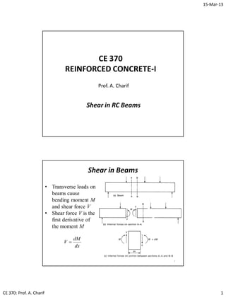
  • 1. 15-Mar-13 CE 370: Prof. A. Charif 1 CE 370 REINFORCED CONCRETE-I Prof. A. Charif Shear in RC Beams Shear in Beams 2 • Transverse loads on beams cause bending moment M and shear force V • Shear force V is the first derivative of the moment M dx dM V 
  • 2. 15-Mar-13 CE 370: Prof. A. Charif 2 Shear in Beams 3 • Bending moment causes normal stresses with compression resisted by concrete and tension by longitudinal steel bars • Bending design delivers required longitudinal steel • Shear force causes shear stress and shear design is performed independently • Shear failure is brittle and dangerous • Shear design must deliver a shear strength equal to or greater than flexural strength • Shear is resisted by concrete and steel stirrups Shear stress in an uncracked section 4 Ib VQ v I My f  • Flexural stress is horizontal (compression in top, tension in bot.) • Shear stress has equal vertical and horizontal components • This leads to inclined principal stresses (normal stress, no shear) beamofWidth fiberaboveareaofmomentFirst inertiaofMomentforceShear    b Q IV
  • 3. 15-Mar-13 CE 370: Prof. A. Charif 3 5 f v v ff fp 2 tan2 22 2 2         principal stresses • The two normal principal stresses (one is tension and other is compression) are inclined and this angle is 450 at the neutral axis level (f = 0) • The inclination angle changes in top (compression side) and bottom (tension side) regions 6 Shear stress and inclined cracking • Principal stress trajectories are flat at top (compression zone) and deep at bottom (tension zone) • Inclined cracks are due to combined flexure and shear • Diagonal tension in tension side must be resisted by adequate web reinforcement
  • 4. 15-Mar-13 CE 370: Prof. A. Charif 4 Average Shear Stress between Cracks 7 jdb V v xb T v jd xV jd M T jd M T ww         isstressshearAverage db V v w  :ACI/SBC Average shear stress must not exceed certain limit Modes of Shear Failure in Normal Beams • Shear behavior and analysis of RC beams is quite complex. • Several experimental studies have been conducted to identify the various modes of failure due to combined shear and bending • Shear behavior and failure is closely related to shear span to depth ratio a /d • For normal beams, shear failure modes are :  Diagonal tension failure  Flexural shear failure  Diagonal compression failure 8
  • 5. 15-Mar-13 CE 370: Prof. A. Charif 5 Diagonal tension Failure (Web-shear cracks) • Web shear cracks occur around neutral axis under large shear force and small bending moment. These cracks are normally at 450 with the horizontal and form near the mid-depth of sections and move on a diagonal path to the tension surface. • Occur at ends of beams at simple supports and at inflection points in continuous beams 9 Flexural-shear Failure (Flexure-shear cracks) • For flexure-shear cracks to occur, the moment must be larger than the cracking moment and the shear must be rather large. • The cracks run at angles of about 450 with the beam axis and often start at the top of the flexural cracks. 10
  • 6. 15-Mar-13 CE 370: Prof. A. Charif 6 Diagonal compression failure • Diagonal compression failure occurs under large shear force. It is characterized by the crushing of concrete. Normally it occurs in beams which are reinforced against heavy shear. 11 12 Modes of Shear Failure in Short and Deep Beams
  • 7. 15-Mar-13 CE 370: Prof. A. Charif 7 Forces in a cracked beam without stirrups • Shear strength mechanism of RC members includes : – Concrete compression force in uncracked region – Aggregate interlocking in cracked zone – Shear across longitudinal steel bars known as dowel force – Shear reinforcement, if present, will also resist the shear force 13 14 Forces in a beam with vertical stirrups
  • 8. 15-Mar-13 CE 370: Prof. A. Charif 8 15 Types of Shear Reinforcement (Stirrups) • Steel stirrups may be inclined along diagonal tension but are usually vertical • Part of longitudinal bars may also be bent up from bottom to top to play role of shear reinforcement and then top steel • Nowadays, stirrups are often vertical 16 Types of Shear Reinforcement • Inclined stirrups and bent up bars are not very practical because of the high labor costs for positioning them. • Nowadays, stirrups are often vertical Bent up bars
  • 9. 15-Mar-13 CE 370: Prof. A. Charif 9 17 Types of Shear Reinforcement (Stirrups) Behavior of RC beams with web reinforcement (Truss Analogy)  Concrete in compression is top chord  Longitudinal tension steel is bottom chord  Stirrups form truss verticals  Concrete between diagonal cracks form the truss diagonals 18
  • 10. 15-Mar-13 CE 370: Prof. A. Charif 10 Shear Stress Transfer in RC Beams • Diagonal cracks will occur in beams with shear reinforcement at almost the same loads that they occur in beams of the same size without shear reinforcement. • The shear reinforcement makes its presence known only after the cracks begin to form. At that time, beams must have sufficient shear reinforcing to resist the shear force not resisted by the concrete. • After a shear crack has developed in a beam, only a little shear can be transferred across the crack unless web reinforcing is used to bridge the gap. When such reinforcing is present, it keeps the pieces of concrete on the two sides of the crack from separating. 19 Benefits of Stirrups  Stirrups carry shear across the crack directly  Promote aggregate interlock  Confine the core of the concrete in the beam thereby increasing strength and ductility  Confine the longitudinal bars and prevent concrete cover from splitting off the beam  Hold the pieces of concrete on either side of the crack together and prevent the crack from propagating into the compression region 20
  • 11. 15-Mar-13 CE 370: Prof. A. Charif 11 CE 370 REINFORCED CONCRETE-I Prof. A. Charif Shear analysis and design of RC beams according to SBC / ACI Codes • SBC, ACI and other codes neglect aggregate interlock and dowel action • Shear force is resisted by compression concrete and by steel stirrups only • Nominal shear strength is therefore: 22 strengthshearStirrups: strengthshearConcrete: s c scn V V VVV  Steel stirrups may be inclined along diagonal tension but are usually vertical Shear Analysis and Design according to SBC / ACI Codes
  • 12. 15-Mar-13 CE 370: Prof. A. Charif 12 Shear Analysis and Design according to SBC / ACI Codes 23 shearin0.75With strengthshearStirrups: strengthshearConcrete: with     s c scnun V V VVVVV Nominal shear strength is provided by concrete and stirrups only Design shear strength must be equal to or greater than ultimate shear • Concrete may provide enough strength to resist ultimate shear but SBC / ACI require stirrups if: 222 c u cuc n V V VVV V    Shear Analysis and Design according to SBC / ACI Codes 24 scnun VVVVV  with • SBC / ACI nominal shear strength of concrete in beams is : db f V w ' c c 6  • For axially loaded members (columns) the nominal shear strength of concrete is : db f A N VN db f A N VN w ' c g u cu w ' c g u cu 6 3.0 1:0)(Tension 614 1:0)(nCompressio                  
  • 13. 15-Mar-13 CE 370: Prof. A. Charif 13 25 Shear Analysis and Design per SBC / ACI   areasection-crossStirrup: cossin:stirrupsInclined :stirrupsVertical v yvs yv yvss A s d fAV s dfA fAnV    • Assuming a 450 inclined crack, the number of vertical stirrups crossed by the crack is ns = d/s where s is the stirrup spacing • Assuming that they have yielded the stirrups shear strength is : Stirrup Section Area • A stirrup has at least one leg but usually two legs or more. 26 diameterStirrup: 4 :legswithStirrup 2 s s v yv s d d nA n s dfA V  
  • 14. 15-Mar-13 CE 370: Prof. A. Charif 14 Section Adequacy for Shear • Before performing design, the section must first be checked whether it is sufficient to resist shear according to SBC / ACI. • The section is insufficient to resist shear and must be increased if : 27 6 5:ifshearforsectionntInsufficie :isconditionthestress,shearaverageofIn terms 5:ifshearforsectionntInsufficie 6 but 3 2 3 2 '' ' c w u u cu w ' c c wcc u wcs f db V v VV db f V dbfV V dbfV        Beam Shear Design Required Vertical Stirrup Spacing 28   trequiremensteelminimumUse0if:Note :spacingstirrupRequired designOptimalwith            c u s c u yv c uyv c u susc unscnun V V V V V dfA s V V s dfA V V VVVV VVVVVVV      22 c u c n V V V V   • SBC / ACI specify that stirrups are required in beams if :
  • 15. 15-Mar-13 CE 370: Prof. A. Charif 15 Minimum Web Reinforcement and Maximum Stirrup Spacing SBC / ACI minimum web steel area : 29 y wc v f sbf A          3 1 , 16 Max ' min,                   (b)Case300,25.0Min3If (a)Case600,5.0Min3If (b)Case300,25.0Min2If (a)Case600,5.0Min2If max max max max mmdsVV mmdsVV mmdsVV mmdsVV cu cu cs cs   SBC / ACI maximum stirrup spacing (geometry considerations) : Critical Shear Sections • Load transfer between beams and supports is performed through conic shaped zones with 450 angles. • Shear failures occur at critical sections located at a distance d from the face of the support, where d is the depth of tension steel • Ultimate shear force considered for design is computed at the critical section 30
  • 16. 15-Mar-13 CE 370: Prof. A. Charif 16 31 Critical Shear Sections Critical Shear Section for Design • Ultimate shear used for design is computed at the critical section at a distance d from the support face (d = Tension steel depth) • It is obtained from support and mid-span values using shear force envelope diagram. • Most modern structural analysis methods use clear length Ln (clear distance between support faces) 32 nL Stirrup reinforcement in beams is usually symmetric about mid-point except in special cases such as cantileversLn/2d VuL/2 Vud Vu0
  • 17. 15-Mar-13 CE 370: Prof. A. Charif 17 Critical Shear Section for Design • For a simply supported beam, the ultimate shear force values at the support and mid-span are : 33 82 2/0 nLu uL nu u Lw V Lw V  wu : Total factored (ultimate) uniform load (= 1.4wD + 1.7wL) wLu : Factored live load (= 1.7wL) Shear force at support is obtained with ultimate uniform load applied on all the span The mid-span value is obtained by applying factored live load on half the span only (along with factored dead load on all span). Ln/2d VuL/2 Vud Vu0 Critical Shear Section for Design 34 Ln/2d VuL/2 Vud Vu0 From similar triangles we obtain the critical shear value at distance d :   8 , 2 with 2 2/0 2/00 nLu uL nu u uLu n uud Lw V Lw V VV L d VV   L 1w 2w SFD82 21 L w L w  8 2 L w        8 3 2 21 L w L w Mid-span shear value
  • 18. 15-Mar-13 CE 370: Prof. A. Charif 18 Shear Design - Summary 1. Determine ultimate shear force at distance d from support face, to be used for design 2. Compute concrete shear strength Vc 3. Check for section adequacy (whether it is sufficient for shear). If insufficient, the section must be increased. 4. Check whether stirrups are required 5. Compute maximum stirrup spacing 6. Compute minimum shear steel area 7. Compute required stirrup spacing 8. Select appropriate stirrup diameter and spacing to satisfy all conditions (maximum spacing, minimum shear steel, required spacing) 35 36 Shear Design - Summary       y wc v cu cu c u cu w ' c c nLu uL nu uuLu n uudu f sbf A mmdsVV mmdsVV V V VV db f V Lw V Lw VVV L d VVV                   3 1 , 16 MaxareasteelshearMinimum/6 (b)300,25.0Min3If (a)600,5.0Min3If :spacingstirrupMaximum/5 2 ifrequiredareStirrups/4 5ifshearforsectionntInsufficie/3 6 /2 8 , 2 with 2 /1 ' min, max max 2/02/00    
  • 19. 15-Mar-13 CE 370: Prof. A. Charif 19 37 Shear Design – Summary Cont. 7step-spacingstirrupRequiredc/ 6step-areasteelshearMinimumb/ 5step-spacinggeometryMaximuma/ :conditionsthreeesatisfy thorder toinspacingstirrup andlegsofnumberdiameter,stirrupeappropriatSelect/8 discardedisspacingrequiredthen,0if:Note spacingstirrupRequired/7    c u s c u yv V V V V V dfA s   • In practice the stirrup diameter ds is usually fixed and the designer must determine the required number of legs and spacing. • ds depends on the diameter of the main bars • In buildings, ds is 10 mm for columns, 8 to10 mm for beams • In bridges ds is higher (12 to 16 mm) 38 Shear Design – Summary Cont. The three SBC / ACI requirements (steps 5 to 7) can be reformulated using the stirrup spacing as the main design variable. The designer usually selects first the stirrup diameter ds, the number of legs n, and then determines the required stirrup spacing s, while satisfying all code requirements. Given its diameter ds and the number of legs n, the stirrup area is: 4 2 s v dn A   The minimum shear steel area requirement, expressed in terms of spacing s, can thus be transformed to another spacing requirement: w yv c y wc v b fA f s f sbf A                   0.3, 0.16 MinspacingsteelMaximum 3 1 , 16 MaxareasteelshearMinimum ' 2 max ' min,
  • 20. 15-Mar-13 CE 370: Prof. A. Charif 20 39 Shear Design - Stirrup Spacing Summary       (b)byorbycontrolledisitifincreasedbeonlycanSpacing (b)casebycontrolledisitunlessunchangedremains decreases.whenincreases.shearultimateondependsOnly notdoesbut)and(onondependand:Notes ,,Min:spacingAdopted :spacingstirrupRequired 0.3, 0.16 Min:spacingsteelMinimum (b)3If300,25.0Min (a)3If600,5.0Min :spacingGeometry 1 max 3 max 1 max 3 max 3 max 1 max 3 max 2 max 3 max 2 max 1 max 3 max ' 2 max 1 max ss s VsVs sdnAss ssss V V dfA s b fA f s VVmmd VVmmd s uu sv c u yv w yv c cu cu                       40 Shear design and spacing c u yv w yv c cu cu V V dfA s b fA f s mm d sVV mm d sVV                                    3 max ' 2 max 1 max 1 max 0.3, 0.16 Min 300, 4 Min:3 600, 2 Min:3 (b) (a) Vu cV5.0 cV3 cV cV5 requiredstirrupsNo 3 maxs (a)Case1 max s 2 (a)Case (b)Case1 max s sectionntInsufficie
  • 21. 15-Mar-13 CE 370: Prof. A. Charif 21 41 ?5 cu VV  dimensionsIncrease sectionntInsufficie ?5.0 cu VV  requirednotStirrups ?3 cu VV  (b)300, 4 Min1 max        mm d s(a)600, 2 Min1 max        mm d s w yv c b fA f s          0.3, 0.16 Min ' 2 max ?cu VV   2 max 1 max ,Min sss  c u yv V V dfA s    3 max  3 max 2 max 1 max ,,Min ssss  Yes No Yes Yes Yes No No No db f V V w ' c c u 6 75.0,known   Shear design Flowchart Shear Design - Observations • The designed stirrup spacing may turn out inadequate in many ways. It could be either too large or too small. • If the spacing is too large, then the number of legs or (and) stirrup diameter may be decreased. • If the spacing is too small, then either the number of legs or stirrup diameter must be increased. • A complete and adequate design strategy is to start using the minimum stirrup diameter and minimum number of legs. • If the spacing is too small (less than 100 mm), increase the number of legs, but if the number of legs is excessive then increase the stirrup diameter. 42
  • 22. 15-Mar-13 CE 370: Prof. A. Charif 22 Shear Design - Full Automatic Algorithm Data includes minimum stirrup diameter dsmin as well as minimum and maximum numbers of legs nmin and nmax Leg increment = 1 , Stirrup diameter increment = 2 mm • Compute s1 max • Start with dsmin • A - Start with nmin • B - Compute stirrup area • Compute s2 max , s3 max and final spacing value • If spacing value is ok stop • If spacing too small then :  If n < nmax : n = n + 1 and goto B  If n = nmax : ds = ds + 2.0 and goto A 43 Stirrup Design Algorithm (Stirrup Diameter, Number of Legs and Spacing) 1. Compute maximum geometry spacing s1 max 2. Start with minimum stirrup diameter dsmin 3. Start with minimum leg number nmin 4. Compute stirrup area 5. Compute minimum steel spacing s2 max 6. If Vu > Vc : s = Min (s1 max , s2 max) 7. If Vu ≤ Vc : Compute required steel spacing s3 max and s = Min (s1 max , s2 max , s3 max) 8. If s ≥ 100 mm then stop 9. If n < nmax then n = n + 1 and goto 4 10. If n = nmax then ds = ds + 2 and goto 44
  • 23. 15-Mar-13 CE 370: Prof. A. Charif 23 Shear Design Problem 1 • A simply supported beam is subjected to uniform loading composed of dead load (including self weight) of 27.0 kN/m and live load of 17.5 kN/m. • The beam clear span length is 9.6 m and the section dimensions are 300 x 600 mm. • Steel depth is d = 540 mm • Design the beam for shear using 10 mm stirrups and the following material data : 45 MPafMPaf yc 42025'  Solution 1 The ultimate load is : wu = 1.4 x 27.0 + 1.7 x 17.5 = 37.8 + 29.75 = 67.55 kN/m Factored live load is : wLu = 1.7 x 17.5 = 29.75 kN/m Ultimate shear force at support and mid-span as well as value at the critical section (at a distance d from the support) are: 46     kNV VV L d VV kN L wV kN L wV ud uLu n uud n LuuL n uu 78.2917.3524.324 6.9 54.02 24.324 2 7.35 8 6.9 75.29 8 24.324 2 6.9 55.67 2 2/00 2/ 0      
  • 24. 15-Mar-13 CE 370: Prof. A. Charif 24 47 Solution 1 – Cont. designforusedis 78.291 7.35 24.324 62.505.0 2/ 0 ud ud uL u c V kNV kNV kNV kNV     Ln/2 = 4.8 m0.54m VuL/2 Vud Vu0 cV5.0 Concrete nominal shear strength is : kNNdb f V w c c 0.135135000540300 6 25 6 '  2 22 6.235 4 103 4 3:stirrupsleg3Use requiredareStirrups625.5050.:trequiremenStirrup OKSection78.29125.50613575.055 :checkadequacySection mm dn An VkNV kNVVkNV s v udc uduc       Solution 1 – Cont. 48   (a)Case0.270600,5.0Min 75.303378.291:spacinggeometryMaximum 1 max mmmmds kNVV cud    mms b fA f s w yv c 5.989 300 4206.235 0.3, 25 0.16 Min 0.3, 0.16 Min:spacingsteelMinimum 2 max ' 2 max                   mms V V dfA s c ud yv 3.210 10000.135 75.0 78.291 5404206.235 :spacingstirrupRequired 3 max 3 max             
  • 25. 15-Mar-13 CE 370: Prof. A. Charif 25 Solution 1 – Cont. Question 1: We used 3 legs. What happens if we use 2 or 4 legs? 49   spacingmm200auseWe 210,,Min:spacingAdopted 3.210:spacingstirrupRequired 5.989:spacingsteelMinimum 0.270:spacingmaximumGeometry :summarytrequiremenspacingMaximum 3 max 2 max 1 max 3 max 2 max 1 max      mmsssss mms mms mms • A stirrup is assumed to resist shear over a distance extending s/2 on each side of the stirrup • The first stirrup must thus be located at a distance s/2 from the support face • First stirrup at 100 mm, then constant 200 mm spacing Solution 1 – Cont. • Using more than three legs is wasteful as spacing becomes controlled by geometry maximum spacing • Question 2 : Can we change spacing when shear force is reduced? 50   mms ssss mms mms 140 ,,Min 2.140 :spacingstirrupRequired 7.659 :spacingsteelMinimum :legsTwo 3 max 2 max 1 max 3 max 2 max     )(0.270:unchangedisspacingmaximumGeometry 1 max amms    mmss ssss mms mms 270 ,,Min 4.280 :spacingstirrupRequired 4.1319 :spacingsteelMinimum :legsFour 1 max 3 max 2 max 1 max 3 max 2 max    
  • 26. 15-Mar-13 CE 370: Prof. A. Charif 26 Stirrup Requirement and Spacing Variation 51 • When shear force is reduced, we can not only change (increase) stirrup spacing, but we may be able to stop stirrups completely when they are no longer required • Remember : Stirrups are required in beams in all zones where: cu VV 5.0 cu VV 5.0 • Stirrups may therefore be required near the beam support and not required in other zones (around the mid-span) where shear force is smaller : 52 Stirrups are no longer required when : cu VV 5.0 Ln/2 VuL/2 Vu0 x0 cV5.0 Distance x0 over which stirrups are required is obtained using similar triangles :          2/0 0 0 5.0 2 uLu cun VV VVL x  • x0 may be greater or less than half-span • In half-span of the beam, stirrups are provided over a distance :        2 ,Min 0 n st L xL Stirrup Requirement and Spacing Variation
  • 27. 15-Mar-13 CE 370: Prof. A. Charif 27 53 • Geometry maximum spacing s1 max is independent of shear steel area Av and thus on number of legs n and stirrup diameter ds, • If the final stirrup spacing is controlled by the geometry limit s1 max case (a), it cannot be increased. The number of legs, or stirrup diameter, may be decreased (if they are not minimal). • Minimum leg number is usually 2 and minimum stirrup diameter is 10 mm for columns and 8 to 10 mm for beams • If the final spacing is controlled by any of the other two limits s2 max or s3 max , then the design is adopted unless the spacing is too small (less than 75 to 100 mm), in which case the number of legs must be increased • If the final spacing is controlled by the required steel limit s3 max this means that it can be varied (increased) at a reduced value of shear force located at a certain distance from the support. Stirrup Requirement and Spacing Variation Stirrup Design Algorithm (Variation of Stirrup Spacing) • If the final stirrup spacing is controlled by required steel limit s3 max then it can be varied (increased) at a reduced value of shear force located at a certain distance from the support • Spacing variation is performed if the required number of stirrups over distance Lst is important (say greater than 10) • The new spacing value is usually 50 to 100 mm greater than the previous one 54 2 max 1 max 1 12 andlimitstwotheexceednotmustspacingnewThe 100to50:generalIn 100to50 ss mmss mmss jj   
  • 28. 15-Mar-13 CE 370: Prof. A. Charif 28 Stirrup Design Algorithm – Cont. (Variation of Stirrup Spacing) • The value of shear force corresponding to the new spacing is deduced from optimal design condition: 55        2 2 s dfA VVV V s dfA V yv cuc uyv s   • Location x2 of this new shear force value is obtained using similar triangles:          2/0 20 2 2 uLu uun VV VVL x Ln/2 VuL/2 Vu0 x2 Vu2 56     1 1 1 1 1 1 2 :lengthstirrupCumulated :spacingsNext5.0:spacingFirst :distancegivenoverstirrupsofnumberRequired i ii i si j sj j s s snL s D n s D n D Spacing Variation
  • 29. 15-Mar-13 CE 370: Prof. A. Charif 29 Stirrup Design Algorithm – Cont. (Variation of Stirrup Spacing) • The number n1 of stirrups with the first spacing value is such : 57 • Spacing variation (increase) may be performed more than once • The distance left for the second spacing is : • The approximate number of stirrups with spacing s2 is : • If this number exceeds ten to twelve, then a further spacing variation may be considered provided the limits are not already reached. 5.0 2 1 2 12 1 1121  s x nx s snxLs 2 1 1112 s snLLLR stsst  2 2 2 s R n  Stirrup Design Algorithm – Cont. (Variation of Stirrup Spacing) • The next shear force value and its location are given by : 58 • The exact distance used by stirrups with preceding spacing and their number are: 3 2 2/0 0                   j VV VVL x s dfA VV uLu ujun j j yv cuj  1 * 1 1 1 2 1 2 1 * 1 2                 j j j j i iij j i sijj s x n s snxLxx • Remaining distance and approximate number of stirrups with new spacing sj are: j j j j iist j i sistj s R n s snLLLR     2 1 1 1 1 1
  • 30. 15-Mar-13 CE 370: Prof. A. Charif 30 Spacing variation algorithm • Compute spacing s1 at critical section • If s1 is controlled by s2 max or by s1 max case (a) then stop • j = 2 A - Choose new spacing sj = sj-1 + 50 to 100 mm • Deduce Vuj and xj • Deduce number of stirrups with previous spacing nj-1 • Remaining distance and number of stirrups Rj and nj • If number nj is large enough and spacing variation is still possible then : j = j+1 and gotoA Note : If s1 is controlled by by s1 max case (b), then the second spacing s2 must be located inside case (a) zone, i.e. with Vu ≤ 3 Vc 59 Shear Design Problem 2 (Same as Problem 1) • A simply supported beam is subjected to uniform loading composed of dead load (including self weight) of 27.0 kN/m and live load of 17.5 kN/m. • The beam clear span length is 9.6 m and the section dimensions are 300 x 600 mm. • Steel depth is d = 540 mm • Design the beam for shear using 10 mm stirrups and the following material data : 60 MPafMPaf yc 42025' 
  • 31. 15-Mar-13 CE 370: Prof. A. Charif 31 Solution 2 • The ultimate load, shear force values and concrete shear strength are the same as before. 61 kNdb f V kNV kNV kNV kNV w c c ud uL u c 0.135 6 78.291 7.35 24.324 62.505.0 ' 2/ 0      Ln/2 = 4.8 m0.54m VuL/2 Vud Vu0 cV5.0 requiredareStirrups62.50 2 :trequiremenStirrup OKSection78.29125.50613575.055 :checkadequacySection   ud c uduc VkN V kNVVkNV   Solution 2 – Cont. 62 • Distance x0 beyond which stirrups are not required is : mmm VV VVL x uLu cun 4552552.4 7.3524.324 13575.05.024.324 2 6.95.0 2 2/0 0 0                     (a)0.270600,5.0Min 75.303378.291 :spacinggeometryMaximum 1 max mmmmds kNVV cud    • This distance x0 is smaller than half-span. Stirrups are thus required over a distance : mmx L xL n st 4552 2 ,Min 00       
  • 32. 15-Mar-13 CE 370: Prof. A. Charif 32 Solution 2 – Cont. 63 mms b fA f s mm dn An = w yv c s v 7.659 300 42008.157 0.3, 25 0.16 Min 0.3, 0.16 Min:spacingsteelMinimum 08.157 4 100 2 4 2:legstwoStart with 2 max ' 2 max 2 2                      mm V V dfA s c ud yv 2.140 10000.135 75.0 78.291 54042008.157 :spacingstirrupRequired 3 max              Solution 2 – Cont. 64   spacingmm100auseWe mm50ofmultiplesasvaluesspacingselectusuallyWe )byd(controlle140 ,,Mins:spacingAdopted 2.140:spacingstirrupRequired 7.659:spacingsteelMinimum 0.270:spacingmaximumGeometry :summarytrequiremenspacingMaximum 3 max 3 max 2 max 1 max 3 max 2 max 1 max       smms sss mms mms mms
  • 33. 15-Mar-13 CE 370: Prof. A. Charif 33 Solution 2 – Cont. Spacing Variation 65 mmm VV VVL x kN s dfA VV mms ss uLu uun yv cu 746746.0 7.3524.324 38.27924.324 2 6.9 2 :isvalueforceshearthisoflocationThe 38.279 1000 1 540 150 42008.157 13575.0 :isforceshearingCorrespond 150spacingsecondachooseWe ,limits twotheofanyexceednotdoesitprovidedincreasedbemaySpacing 2/0 20 2 2 2 2 2 max 1 max                                   Solution 2 – Cont. Spacing Variation 66 The total number of stirrups with first spacing is : 896.7 2 1 100 746 2 1 2 1 1 2 12 1 1121  n s x nx s snxLs mmLLR mm s snLLLR sst ssst 38027504552 750 2 100 1008 2 12 1 11112   The approximate number of stirrups with spacing s2 is : 3.25 150 3802 2 2 2  s R n The first stirrup is at a distance s1/2 = 50 mm. Seven more stirrups are needed to cover this distance x2 (= 746 mm) The remaining distance for spacing s2 is :
  • 34. 15-Mar-13 CE 370: Prof. A. Charif 34 Solution 2 – Cont. Spacing Variation 67 This large number allows for further spacing variation (which is still possible). We chose a new (third) value of 250 mm (which corresponds in fact to geometry maximum spacing) : s3 = 250 mm The corresponding shear force value and its location are : 3.25 150 3802 2 2 2  s R n mmm VV VVL x kN s dfA VV uLu uun yv cu 1932932.1 7.3524.324 13.20824.324 2 6.9 2 13.208 1000 1 250 54042008.157 13575.0 2/0 30 3 3 3                                 Solution 2 – Cont. Spacing Variation 68 mmxkNVu 193213.208 33  The exact distance used by stirrups with spacing s2 and their number are: mmsnL n s x n mmLxx s s 12001508 888.7 150 1182 11827501932 222 2 2 * 2 2 13 * 2    Remaining distance and approximate number of stirrups with spacing s3 are : mmsnL n s R n mmLLLR s ssst 275025011 1141.10 250 2602 260212007504552 333 3 3 3 3 213   
  • 35. 15-Mar-13 CE 370: Prof. A. Charif 35 Solution 2- Summary Stirrups required over a distance Lst = 4552 mm (less than half-span) Use of two-leg 10 mm stirrups as follows: 1. Eight stirrups with spacing s1 = 100 mm. First stirrup located at s1/2 = 50 mm, and then seven stirrups with spacing s1 = 100 mm (Ls1 = 50 + 7 x 100 = 750 mm) 2. Eight stirrups with spacing s2 = 150 mm (Ls2 = 8 x 150 = 1200 mm and Ls1 + Ls2 = 1950 mm) 3. Eleven stirrups with spacing s3 = 250 mm (Ls3 = 2750 mm , and Ls1 + Ls2 + Ls3 = 4700 mm) 69 70 Figure produced by RC-TOOL software implementing all previous theory Same results with shear force diagrams Solution 2 - Summary   DemandOfferSafety :(offer)capacityDesign :(demand)shearUltimate :diagramsforceShear   scn n u VVV V V  
  • 36. 15-Mar-13 CE 370: Prof. A. Charif 36 Shear Design Problem 3 (Same as Problem 2) • Same beam and same data except that we use 8-mm stirrups. • For a two-leg 8-mm stirrup, shear steel area is 71 mm V V dfA s mm b fA f s mms mm dn A c ud yv w yv c s v 7.89 10000.135 75.0 78.291 54042053.100 2.422420 300 53.100 0.3, 25 16 Min0.3, 0.16 Min :arespacingrequiredandspacingsteelMinimum (a)0.270unchnagedisspacingmaximumGeometry 53.10032 4 64 2 4 3 max ' 2 max 1 max 2 2                                  72 Solution 3 • The final spacing value controlled by the required spacing limit (89.7 mm) is small and less than the minimum limit of 100 mm. • To increase the required spacing, we must increase the number of legs (or the stirrup diameter) • We keep using the same 8-mm stirrup diameter and increase the number of legs to three. The maximum geometry spacing remains unchanged but the other two will increase: mm V V dfA s mm b fA f s mm dn Amms c ud yv w yv c s v 6.134 10000.135 75.0 78.291 5404208.150 3.633420 300 8.150 0.3, 25 16 Min0.3, 0.16 Min 8.15048 4 64 3 4 0.270 3 max ' 2 max 2 2 1 max                                
  • 37. 15-Mar-13 CE 370: Prof. A. Charif 37 73   spacingmm100auseWe mm50ofmultiplesasvaluesspacingselectusuallyWe )byd(controlle134 ,,Min:spacingAdopted 6.134:spacingstirrupRequired 3.633:spacingsteelMinimum 0.270:spacingmaximumGeometry :stirrupsmm8leg-for threesummarytrequiremenspacingMaximum 3 max 3 max 2 max 1 max 3 max 2 max 1 max       smms ssss mms mms mms Solution 3 – Cont. Solution 3 – Cont. Spacing Variation 74 mmm VV VVL x kN s dfA VV mms ss uLu uun yv cu 865865.0 7.3524.324 26.27224.324 2 6.9 2 :isvalueforceshearthisoflocationThe 26.272 1000 1 540 150 4208.150 13575.0 :isforceshearingCorrespond 150spacingsecondachooseWe ,limitstwothe ofanyexceednotdoesitprovidedincreasedbemaySpacing 2/0 20 2 2 2 2 2 max 1 max                                  
  • 38. 15-Mar-13 CE 370: Prof. A. Charif 38 Solution 3 – Cont. Spacing Variation 75 The total number of stirrups with first spacing is : mmL n s x nx s snxL s s 950100950 1015.9 2 1 100 865 2 1 2 1 1 1 2 12 1 1121   mmLLR sst 3602950455212  The approximate number of stirrups with spacing s2 is : 01.24 150 3602 2 2 2  s R n The first stirrup is at a distance s1/2 = 50 mm. Nine more stirrups are needed to cover this distance x2 (= 865 mm) The remaining distance for spacing s2 is : Solution 3 – Cont. Spacing Variation 76 This large number allows for further spacing variation. We chose a new (third) value of 250 mm (which corresponds in fact to geometry maximum spacing) : s3 = 250 mm The corresponding shear force value and its location are : 01.24 150 3602 2 2 2  s R n mmm VV VVL x kN s dfA VV uLu uun yv cu 2003003.2 7.3524.324 85.20324.324 2 6.9 2 85.203 1000 1 250 5404208.150 13575.0 2/0 30 3 3 3                                
  • 39. 15-Mar-13 CE 370: Prof. A. Charif 39 Solution 3 – Cont. Spacing Variation 77 mmxkNVu 200385.203 33  The exact distance used by stirrups with spacing s2 and their number are: mmsnL n s x n mmLxx s s 12001508 802.7 150 1053 10539502003 222 2 2 * 2 2 13 * 2    Remaining distance and number of stirrups with spacing s3 are : mmsnL n s R n mmLLLR s ssst 250025010 107.9 250 2402 240212009504552 333 3 3 3 3 213    Solution 3 - Summary Stirrups required over a distance Lst = 4552 mm (less than half-span) Use of three-leg 8 mm stirrups as follows: 1. Ten stirrups with spacing s1 = 100 mm and the first stirrup is at s1/2 = 50 mm, (Ls1 = 50 + 9 x 100 = 950 mm) 2. Eight stirrups with s2 = 150 mm (Ls2 = 8 x 150 = 1200 mm and Ls1 + Ls2 = 2150 mm) 3. Ten stirrups with s3 = 250 mm (Ls3 = 10 x 250 = 2500 mm and Ls1 + Ls2 + Ls3 = 4650 mm) • Total : 28 three-leg stirrups • The same results are delivered by RC-TOOL software as shown in the figure 78
  • 40. 15-Mar-13 CE 370: Prof. A. Charif 40 79 RC-TOOL Solution of Problem 3 Comments about Problem 3 • It may happen that the required number of legs at the critical section is greater than the minimum limit. This value can be used throughout the beam but it can also be reduced for lower shear force values. • When the number of legs necessary at the critical section is greater than the minimum limit (as in example 3), it can be reduced at a certain distance when the spacing is controlled by the maximum geometry spacing s1 max • The last ten stirrups with 250 mm spacing can thus be replaced with two legged stirrups with an adequate spacing to be calculated. • Using two legs for the third spacing will also affect the number of stirrups using the second spacing (this number n2 will increase as the stopping of spacing 2 will be delayed). 80
  • 41. 15-Mar-13 CE 370: Prof. A. Charif 41 Reducing number of legs • Reducing the number of legs to two, we have for 8-mm stirrups: 81 mms mm b fA f s mms mm dn A w yv c s v 250spacingchosenthetoequalbeshouldIt laterestimatedbelimit willspacingstirrupRequired 2.422420 300 53.100 0.3, 25 16 Min0.3, 0.16 Min :isspacingsteelMinimum 0.270unchnagedisspacingmaximumGeometry 53.10032 4 64 2 4 3 ' 2 max 1 max 2 2                      82 Using two legs and a value of 250 mm (which corresponds in fact to geometry maximum spacing) : s3 = 250 mm The corresponding shear force value and its location are : mms mm V V dfA s mmm VV VVL x kN s dfA VV c ud yv uLu uun yv cu 250spacingofchoiceourconfirmsThis 0.250 10000.135 75.0 65.169 54042053.100 :limitspacingrequiredingcorrespondCheck 2572572.2 7.3524.324 65.16924.324 2 6.9 2 65.169 1000 1 250 54042053.100 13575.0 3 3 max 2/0 30 3 3 3                                                Reducing number of legs
  • 42. 15-Mar-13 CE 370: Prof. A. Charif 42 Reducing number of legs 83 mmxkNVu 257265.169 33  The exact distance used by stirrups with spacing s2 (with three legs) and their number are: mmsnL n s x n mmLxx s s 165015011 1181.10 150 1622 16229502572 222 2 2 * 2 2 13 * 2    Remaining distance and number of stirrups with spacing s3 are : mmsnL n s R n mmLLLR s ssst 20002508 88.7 250 1952 195216509504552 333 3 3 3 3 213    Reducing number of legs Summary Stirrups required over a distance Lst = 4552 mm (less than half-span) First, use of three-leg 8 mm stirrups as follows: 1. Ten stirrups with spacing s1 = 100 mm. First stirrup located at s1/2 = 50 mm, (Ls1 = 50 + 9 x 100 = 950 mm) 2. Eleven stirrups with s2 = 150 mm (Ls2 = 11 x 150 = 1650 mm and Ls1 + Ls2 = 2600 mm) 3. Use two leg stirrups : Eight stirrups with spacing s3 = 250 mm (Ls3 = 8 x 250 = 2000 mm and Ls1 + Ls2 + Ls3 = 4600 mm) • Total : 29 stirrups of 8-mm diameter composed of :  21 three-leg stirrups and 8 two-leg stirrups 84
  • 43. 15-Mar-13 CE 370: Prof. A. Charif 43 85 Reducing number of legs Shear Design Problem 4 (High shear force value) • We study the same previous beam but with higher loading. • Dead load (including self weight) = 40.0 kN/m • Live load = 20.0 kN/m. • The beam clear span length is 9.6 m and the section dimensions are 300 x 600 mm. • Tension steel depth is d = 540 mm • Design the beam for shear using 10 mm stirrups and the following material data : 86 MPafMPaf yc 42025' 
  • 44. 15-Mar-13 CE 370: Prof. A. Charif 44 Solution 4 The ultimate load is : wu = 1.4 x 40.0 + 1.7 x 20.0 = 56.0 + 34.0 = 90.0 kN/m Factored live load is : wLu = 1.7 x 20.0 = 34.0 kN/m Ultimate shear force at support and mid-span as well as value at distance d are: 87     kNV VV L d VV kN L wV kN L wV ud uLu n uud n LuuL n uu 99.3878.400.432 6.9 54.02 0.432 2 8.40 8 6.9 0.34 8 0.432 2 6.9 0.90 2 2/00 2/ 0       88 Solution 4 designforusedis 99.387 8.40 0.432 75.3033 62.505.0 2/ 0 ud ud uL u c c V kNV kNV kNV kNV kNV        Ln/2 = 4.8 m0.54m VuL/2 Vud Vu0 cV5.0 cV3 requiredareStirrups62.50 2 :trequiremenStirrup OKSection99.38725.50613575.055 :checkadequacySection 0.135135000540300 6 25 6 :shearConcrete '    ud c uduc w c c VkN V kNVVkNV kNNdb f V  
  • 45. 15-Mar-13 CE 370: Prof. A. Charif 45 Solution 4 – Cont. 89   mms b fA f s mm dn An = mmmmds kNVV w yv c s v cud 7.659 300 42008.157 0.3, 25 0.16 Min 0.3, 0.16 Min:spacingsteelMinimum 08.157 4 100 2 4 2:legstwoStart with (b)casebycontrolled(b)0.135300,25.0Min 75.303399.387:spacinggeometryMaximum 2 max ' 2 max 2 2 1 max                         Distance x0 over which stirrups are required is : mmx L xL L x mmm VV VVL x n st n uLu cun 4679 2 ,Min:distancestirrupRequired. 2 ansmaller thjust 4679679.4 8.400.432 13575.05.00.432 2 6.95.0 2 000 2/0 0 0                          Solution 4 – Cont. 90 )(unchanged0.135 77.139 10000.135 75.0 99.387 54042062.235 and 6.989 300 42062.235 0.3, 25 0.16 Min0.3, 0.16 Min 62.235 4 100 3 4 3:threetolegsofnumber theincreasethereforeWemm).100than(lesssmallisvaluespacingThis 18.93 10000.135 75.0 99.387 54042008.157 :spacingstirrupRequired 1 max 3 max ' 2 max 2 2 3 max mms mm V V dfA s mm b fA f s mm dn An mm V V dfA s c ud yv w yv c s v c ud yv                                                
  • 46. 15-Mar-13 CE 370: Prof. A. Charif 46 Solution 4 – Cont. 91   spacingmm100auseWe mm50ofmultiplesasvaluesspacingselectusuallyWe )byd(controlle135 ,,Mins:spacingAdopted 77.139:spacingstirrupRequired 6.989:spacingsteelMinimum 0.135:spacingmaximumGeometry :summarytrequiremenspacingMaximum 1 max 3 max 2 max 1 max 3 max 2 max 1 max       smms sss mms mms mms 92 Solution 4 – Cont. mmsn s L n s x nx s sn mmm VV VVL x s s NkV s s s h h uLu cun h c 16501001650)1( 2 1724.16 2 1 100 1574 2 1 2 :spacingmm100withdistancecover thistorequiredstirrupsofNumber 1574574.1 8.400.432 13575.030.432 2 6.93 2 :doubledbewillwhichbeyondDistance doubled.valueitsand(a)casebycontrolledbecomewill ),75.3033than(lessesshear valureducedFor force.shearhighaofbecause(b)casebycontrolledis problem,in thisHoweverchanged.bereforecannot theIt limitgeometrymaximumby thecontrolledisspacingFinal 11 1 1 1 1 1 1 11 2/0 0 1 max 1 max 1 max 1 max                      
  • 47. 15-Mar-13 CE 370: Prof. A. Charif 47 93 Solution 4 – Cont.       part.secondin thespacingmm200aadoptWe 20.204 10000.135 75.0 525.297 54042062.235 )(unchanged6.9890.270:arespacingsThe value.forceshearfor thisspacingstirrupnewdesignnowcanWe 525.2978.400.432 9600 16502 0.432 2 :islocationat thisforceshearThe 0.270600,5.0Min :doubledisspacingmaximumgeometrythe span),-halftheofpart(seconddistancethisBeyond 16501001650 3 max 2 max 1 max 2/0 1 01 1 max 1                    mm V V dfA s mmsmms kNVV L L VV mmmmds mmL c ud yv uLu n s us s  Solution 4 – Cont. Spacing Variation 94 mmm VV VVL x kN s dfA VV mms s R n mmLLR uLu uun yv cu sst 2091091.2 8.400.432 57.2610.432 2 6.9 2 :isvalueforceshearthisoflocationThe 57.261 1000 1 540 250 42062.235 13575.0 :isforceshearingCorrespond 250spacingthirdachooseWe possibleisincreasespacingFurther15.15 200 3029 :spacingsecondwithstirrupsofnumberRequired 302916504679distancestirrupRemaining 2/0 30 3 3 3 3 2 2 2 12                                    
  • 48. 15-Mar-13 CE 370: Prof. A. Charif 48 Solution 4 – Cont. Spacing Variation 95 mmxkNVu 209157.261 33  The exact distance used by stirrups with spacing s2 and their number are: mmsnL n s x n mmLxx s s 6002003 3205.2 200 441 44116502091 222 2 2 * 2 2 13 * 2    Remaining distance and approximate number of stirrups with spacing s3 are : mmsnL n s R n mmLLLR s ssst 250025010 10716.9 250 2429 242960016504679 333 3 3 3 3 213    Solution 4 - Summary Stirrups required over a distance Lst = 4679 mm (less than half-span) Use of three-leg 10 mm stirrups as follows: 1. Seventeen stirrups with spacing s1 = 100 mm. First stirrup located at s1/2 = 50 mm (Ls1 = 50 + 16 x 100 =1650 mm) 2. Three stirrups with s2 = 200 mm (Ls2 = 3 x 200 = 600 mm and Ls1 + Ls2 = 2250 mm) 3. Ten stirrups with s3 = 250 mm (Ls3 = 10 x 250 = 2500 mm and Ls1 + Ls2 + Ls3 = 4750 mm) 96
  • 49. 15-Mar-13 CE 370: Prof. A. Charif 49 97 RC-TOOL output 98 RC-TOOL output – Reduction of leg number
  • 50. 15-Mar-13 CE 370: Prof. A. Charif 50 Problem 5 • A simply supported beam is subjected to uniform loading composed of dead load (including self weight) of 60.0 kN/m and live load of 90.0 kN/m. • Span length and section data are shown • Design the beam for shear using 10 mm stirrups 99 MPafMPaf yc 42030'  550d 625 375 304 75 300 300 4200 mmLLmmL n 42003004500  Solution 5 The ultimate load is : wu = 1.4 x 60.0 + 1.7 x 90.0 = 237.0 kN/m Factored live load is : wLu = 1.7 x 90.0 = 153.0 kN/m Ultimate shear force at support and mid-span as well as value at distance d are: 100     kNV VV L d VV kN L wV kN L wV ud uLu n uud n LuuL n uu 4.388325.807.497 2.4 55.02 7.497 2 325.80 8 2.4 0.153 8 7.497 2 2.4 0.237 2 2/00 2/ 0      
  • 51. 15-Mar-13 CE 370: Prof. A. Charif 51 101 Solution 5 – Cont. designforused4.388 325.807.497 6.705.0 2/0 kNV kNVkNV kNV ud uLu c    Ln/2 = 2.1 m0.55m VuL/2 Vud Vu0 cV5.0 span-halffulloverrequiredStirrups 2 325.80 requiredareStirrups6.7050.:trequiremenStirrup OKSection4.388125.7063.18875.055 :checkadequacySection 3.188188279550375 6 30 6 :shearConcrete 2/ '     c uL udc uduc w c c V V VkNV kNVVkNV kNNdb f V    Solution 5 – Cont. 102   (a)Case0.275600,5.0Min 9.56434.388:spacinggeometryMaximum 1 max mmmmds kNVV cud    mms b fA f s mm dn An = w yv c s v 9.513 375 42008.157 0.3, 30 0.16 Min 0.3, 0.16 Min:spacingsteelMinimum 08.157 4 100 2 4 2:legstwoStart with 2 max ' 2 max 2 2                      mm LL xL mmm VV VVL x nn st uLu cun 2100 22 ,Min 2149149.2 325.807.497 3.18875.05.07.497 2 2.45.0 2 0 2/0 0 0                         
  • 52. 15-Mar-13 CE 370: Prof. A. Charif 52 Solution 5 – Cont. 103 mm V V dfA s c ud yv 1.110 10003.188 75.0 4.388 55042008.157 :spacingstirrupRequired 3 max                spacingmm100auseWe )byd(controlle110 ,,Min:spacingAdopted 1.110:spacingstirrupRequired 9.513:spacingsteelMinimum 0.275:spacingmaximumGeometry :summarytrequiremenspacingMaximum 3 max 3 max 2 max 1 max 3 max 2 max 1 max       smms ssss mms mms mms Solution 5 – Cont. Spacing Variation 104 mmm VV VVL x kN s dfA VV mms ss uLu uun yv cu 881881.0 325.807.497 65.3227.497 2 2.4 2 :isvalueforceshearthisoflocationThe 65.322 1000 1 150 55042008.157 3.18875.0 :isforceshearingCorrespond 150spacingsecondachooseWe andlimitstwothe ofanyexceednotdoesitprovidedincreasedbemaySpacing 2/0 20 2 2 2 2 2 max 1 max                                  
  • 53. 15-Mar-13 CE 370: Prof. A. Charif 53 Solution 5 – Cont. Spacing Variation 105 The total number of stirrups with first spacing is : mm s snL n s x n s 950 2 100 15010 2 1031.9 2 1 100 881 2 1 1 111 1 1 2 1   The remaining distance for spacing s2 is : mmLLR sst 1150950210012  The approximate number of stirrups with spacing s2 is : 67.7 150 1150 2 2 2  s R n Solution 5 – Cont. Spacing Variation 106 • We can thus use 8 stirrups with spacing 150 mm or perform a new spacing variation • The number of stirrups with spacing s2 is not very large • We may decide that there is no need for a new spacing variation • RC-TOOL software performs spacing variation if the stirrup number exceeds five 67.7 150 1150 2 2 2  s R n
  • 54. 15-Mar-13 CE 370: Prof. A. Charif 54 Solution 5a - Summary Stirrups required over a distance Lst = 2100 mm (Half-span) Use of two-leg 10 mm stirrups as follows: 1. Ten stirrups with spacing s1 = 100 mm. First stirrup located at s1/2 = 50 mm (Ls1 = 950 mm) 2. Eight stirrups with spacing s2 = 150 mm (Ls2 = 1200 mm and Ls1 + Ls2 = 2150 mm) 3. The extra 50 mm can be easily corrected by many ways, such as adding one more stirrup at a spacing s1 : 4. Eleven stirrups with spacing s1 = 100 mm. First stirrup located at s1/2 = 50 mm (Ls1 = 1050 mm) 5. Seven stirrups with spacing s2 = 150 mm (Ls2 = 1050 mm and Ls1 + Ls2 = 2100 mm)  Total of 18 stirrups in half-span and 35 in the beam. 107 RC-TOOL Solution 5b More Spacing Variation 108 We chose a new (third) value of 250 mm (which corresponds in fact to geometry maximum spacing) : s3 = 250 mm The corresponding shear force value and its location are : mmm VV VVL x kN s dfA VV uLu uun yv cu 1246246.1 325.807.497 08.2507.497 2 2.4 2 08.250 1000 1 250 55042008.157 3.18875.0 2/0 30 3 3 3                                 67.7 150 1150 2 2 2  s R n
  • 55. 15-Mar-13 CE 370: Prof. A. Charif 55 109 mmxkNVu 124608.250 33  The exact distance used by stirrups with spacing s2 and their number are: mmLn s x n mm s snxx s 3001502297.1 150 296 296 2 100 100101246 2 22 2 * 2 2 1 113 * 2   Remaining distance and approximate number of stirrups with spacing s3 are : 34.3 250 850 8503009502100 3 3 3 3 213   n s R n mmLLLR ssst RC-TOOL Solution 5b Spacing Variation 110 span-halfsecondtheof symmetrybycoveredbewillandspacinghalfthanlessisspan-midto distanceremainingthat themeans)4.3(because),3(takeWe 34.3 250 850 8503009502100 33 3 3 3 3 213    nn n s R n mmLLLR ssst RC-TOOL Solution 5b Spacing Variation
  • 56. 15-Mar-13 CE 370: Prof. A. Charif 56 RC-TOOL Solution 5b - Summary Stirrups required over a distance Lst = 2100 mm (Half-span) Use of two-leg 10 mm stirrups as follows: 1. Ten stirrups with spacing s1 = 100 mm. First stirrup located at s1/2 = 50 mm (Ls1 = 950 mm) 2. Two stirrups with spacing s2 = 150 mm (Ls2 = 300 mm and Ls1 + Ls2 = 1250 mm) 3. Three stirrups with spacing s3 = 250 mm (Ls23 = 750 mm and Ls1 + Ls2 + Ls23 = 2000 mm) 4. Remaining distance to mid-span is 100 mm and is less than half of spacing s3 111 112 RC-TOOL Solution Total of 15 stirrups in half-span and 30 in beam (five less than in solution 1)