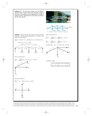
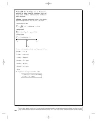
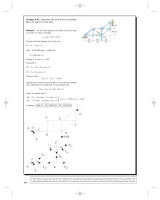
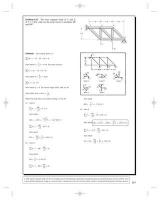
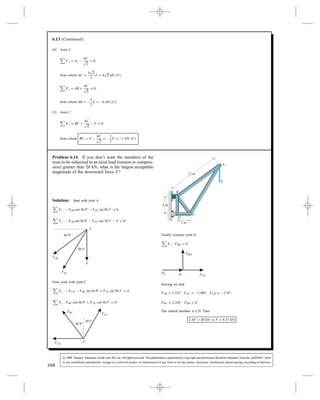
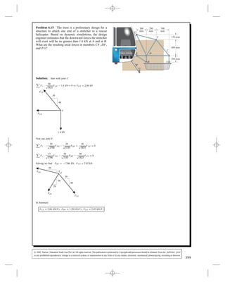
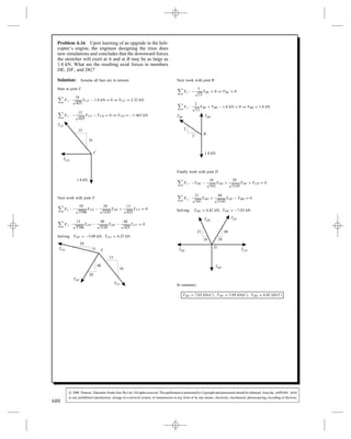
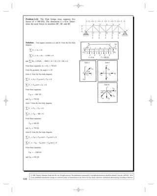
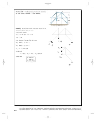
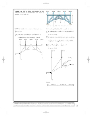
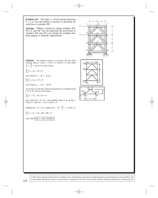
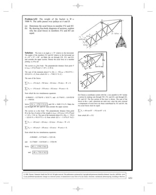
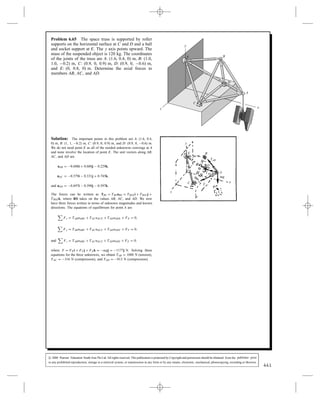
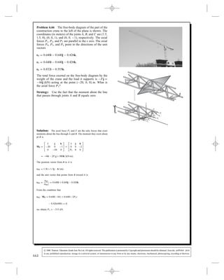
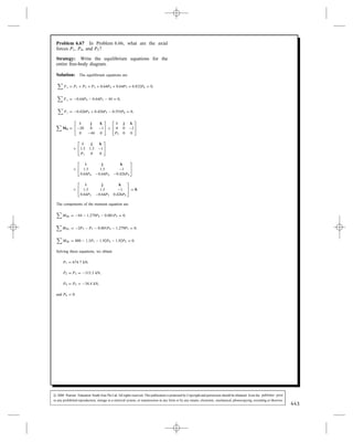
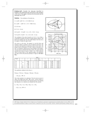
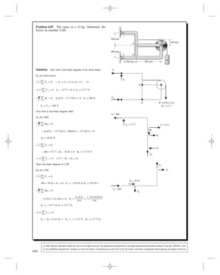
SlideShare a Scribd company logo
1 of 125
Download to read offline
Problem 6.1 In Active Example 6.1, suppose that in
addition to the 2-kN downward force acting at point D,
a 2-kN downward force acts at point C. Draw a sketch of
the truss showing the new loading. Determine the axial
forces in members AB and AC of the truss.
C
5 m
5 m
A
D
B
2 kN
3 m
3 m
Solution: The new sketch, a free-body diagram of the entire truss
and a free-body diagram of the joint at A are shown. The angle ˛
between CD and BD is
˛ D tan 1
6/10 D 31.0°
Using the entire truss, the equilibrium equations are
Fx : Ax C B D 0
Fy : Ay 2 kN 2 kN D 0
MA : 2 kN 5 m 2 kN 10 m
C B 6 m D 0
Solving yields
Ax D 5 kN, Ay D 4 kN, B D 5 kN
Using the free-body diagram of joint A, the equilibrium equations are:
Fx : Ax C TAC cos ˛ D 0
Fy : Ay TAB TAC sin ˛ D 0
Solving yields TAB D 1 kN, TAC D 5.83 kN
Because both values are positive, we know that both are in tension
AB : 1 kN (T), AC : 5.83 kN (T)
386
c 2008 Pearson Education South Asia Pte Ltd. All rights reserved. This publication is protected by Copyright and permission should be obtained from the publisher prior
to any prohibited reproduction, storage in a retrieval system, or transmission in any form or by any means, electronic, mechanical, photocopying, recording or likewise.
Problem 6.2 Determine the axial forces in the
members of the truss and indicate whether they are in
tension (T) or compression (C).
C
800 N
0.7 m
0.7 m
A
B
0.4 m
20Њ
Solution: We start at joint A
Fx :
7
p
65
FAB C
7
p
65
FAC 800 N sin 20° D 0
Fy :
4
p
65
FAB
4
p
65
FAC 800 N cos 20° D 0
Solving we have FAB D 915 N, FAC D 600 N
7 7
44
800 N
A
FACFAB
20°
Next we move to joint C
Fx :
7
p
65
FAC FBC D 0 ) FBC D 521 N
C
Cy
FAC
FCB
7
4
In summary we have
FAB D 915 N C , FAC D 600 N C , FBC D 521 N T
Problem 6.3 Member AB of the truss is subjected to a
000 tensile force. Determine the weight W and the
axial force in member AC.
A
B
W
C
2 m
2 m 2 m
Solution: Using joint A
Fx :
2
p
5
1
p
2
FAC D 0
Fy :
1
p
5
000
1
p
2
FAC W D 0
Solving we have FAC D , W D
In summary we have
W D , FAC D C
000
A2
1
1
1
FAC
W
5 N
387
5 N
5000 N
5 N
6325 N 2236 N
2236 N 6325 N
c 2008 Pearson Education South Asia Pte Ltd. All rights reserved. This publication is protected by Copyright and permission should be obtained from the publisher prior
to any prohibited reproduction, storage in a retrieval system, or transmission in any form or by any means, electronic, mechanical, photocopying, recording or likewise.
Problem 6.4 Determine the axial forces in members
BC and CD of the truss.
600 N
D
E
3
3
3
3 m
A
C
B
m
m
m
Solution: The free-body diagrams for joints E, D, and C are
shown. The angle ˛ is
˛ D tan 1
3/4 D 36.9°
Using Joint E, we have
Fx : 600 N TCE sin ˛ D 0
Fy : TCE cos ˛ TDE D 0
Using Joint D, we have
Fx : TCD TBD sin ˛ D 0
Fy : TDE TBD cos ˛ D 0
Finally, using Joint C, we have
Fx : TCD C TCD sin ˛ TAC sin ˛ D 0
Fy : TCE cos ˛ TAC cos ˛ TBC D 0
Solving these six equations yields
TCE D 1000 N, TDE D 800 N
TCD D 600 N, TAC D 2000 N
TBC D 800 N, TBD D 1000
A positive value means tension and a negative value means compres-
sion
Thus BC : 800 N(T), CD : 600 (C)
388
600 N
N
N
c 2008 Pearson Education South Asia Pte Ltd. All rights reserved. This publication is protected by Copyright and permission should be obtained from the publisher prior
to any prohibited reproduction, storage in a retrieval system, or transmission in any form or by any means, electronic, mechanical, photocopying, recording or likewise.
Problem 6.5 Each suspended weight has mass m D
20 kg. Determine the axial forces in the members of
the truss and indicate whether they are in tension (T) or
compression (C).
0.32 m
0.16 m0.16 m
0.4 m
A
B
C D
m m
Solution: Assume all bars are in tension. Start with joint D
Fy :
5
p
61
TAD 196.2 N D 0
Fx :
6
p
61
TAD TCD D 0
Solving: TAD D 306 N, TCD D 235 N
TAD
TCD
5
6
196.2 N
D
Now work with joint C
Fy :
5
p
29
TAC 196.2 N D 0
Fx :
2
p
29
TAC TBC C TCD D 0
Solving: TAC D 211 N, TBC D 313 N
TAC
5
2
196.2 N
C
TBC TCD
Finally work with joint A
Fy :
5
p
29
TAB C TAC
5
p
61
TAD D 0
) TAB D 423 N
T
TAB TAC
TAD
A
2
2
5 5
5
6
In summary:
TAB D 423 N C
TAC D 211 N T
TAD D 306 N T
TBC D 314 N C
TCD D 235 N C
389
c 2008 Pearson Education South Asia Pte Ltd. All rights reserved. This publication is protected by Copyright and permission should be obtained from the publisher prior
to any prohibited reproduction, storage in a retrieval system, or transmission in any form or by any means, electronic, mechanical, photocopying, recording or likewise.
Problem 6.6 Determine the largest tensile and com-
pressive forces that occur in the members of the truss,
and indicate the members in which they occur if
(a) the dimension h D 0.1 m;
(b) the dimension h D 0.5 m.
Observe how a simple change in design affects the
maximum axial loads.
0.6 m
0.4 m
h
1.2 m
0.7 m1 kN
C
D
B
A
Solution: To get the force components we use equations of the
form TPQ D TPQePQ D TPQXi C TPQYj where P and Q take on the
designations A, B, C, and D as needed.
Equilibrium yields
At joint A:
Fx D TABX C TACX D 0,
and Fy D TABY C TACY 1 kN D 0.
At joint B:
Fx D TABX C TBCX C TBDX D 0,
and Fy D TABY C TBCY C TBDY D 0.
At joint C:
Fx D TBCX TACX C TCDX D 0,
and Fy D TBCY TACY C TCDY C CY D 0.
At joint D:
Fx D TCDX TBDX C DX D 0,
and Fy D TCDY TBDY C DY D 0.
Solve simultaneously to get
TAB D TBD D 2.43 kN,
TAC D 2.78 kN,
TBC D 0, TCD D 2.88 kN.
Note that with appropriate changes in the designation of points, the
forces here are the same as those in Problem 6.4. This can be explained
by noting from the unit vectors that AB and BC are parallel. Also note
that in this configuration, BC carries no load. This geometry is the
same as in Problem 6.4 except for the joint at B and member BC
which carries no load. Remember member BC in this geometry — we
will encounter things like it again, will give it a special name, and will
learn to recognize it on sight.
0.6 m 1.2 m
CY
DY
DX
TBC
−TBC
TBD
TCD
TAB
TAC
−TAB
−TAC−TCD
−TBD
B
y
h
C
D
A
x
1 kN
0.4
m
0.7 m
(b) For this part of the problem, we set h D 0.5 m. The unit vectors
change because h is involved in the coordinates of point B. The new
unit vectors are
eAB D 0.986i C 0.164j,
eAC D 0.864i 0.504j,
eBC D 0i 1j,
eBD D 0.768i 0.640j,
and eCD D 0.832i C 0.555j.
We get the force components as above, and the equilibrium forces at
the joints remain the same. Solving the equilibrium equations simul-
taneously for this situation yields
TAB D 1.35 kN,
TAC D 1.54 kN,
TBC D 1.33,
TBD D 1.74 kN,
and TCD D 1.60 kN.
These numbers differ significantly from (a). Most significantly,
member BD is now carrying a compressive load and this has reduced
the loads in all members except member BD. “Sharing the load” among
more members seems to have worked in this case.
390
c 2008 Pearson Education South Asia Pte Ltd. All rights reserved. This publication is protected by Copyright and permission should be obtained from the publisher prior
to any prohibited reproduction, storage in a retrieval system, or transmission in any form or by any means, electronic, mechanical, photocopying, recording or likewise.
Problem 6.7 This steel truss bridge is in the Gallatin
National Forest south of Bozeman, Montana. Suppose
that one of the tandem trusses supporting the bridge is
loaded as shown. Determine the axial forces in members
AB, BC, BD, and BE.
A
B D F
H
GEC
0 k 0 k 0 k5 N 5 N 5 N
5.1 m 5.1 m 5.1 m 5.1 m
2.4 m
Solution: We start with the entire structure in order to find the
reaction at A. We have to assume that either A or H is really a roller
instead of a pinned support.
MH : 0 k C 0 k C 0 k 5
A D 0 ) A D 5 k
A 0 k H
5.1 m 5.1 m 5.1 m 5.1 m
50 kN 50 kN 5 N
Now we examine joint A
Fy : p
31.77
FAB C A D 0 ) FAB D kN
17
8
A
FAB
FAC
Now work with joint C
Fy : FBC D 0 ) FBC D 0 k
FAC FCE
FBC
C
0 k5 N
Finally work with joint B
Fx : p FAB C p FBE C FBD D 0
Fy : p FAB p FBE FBC D 0
Solving we find FBD D k , FBE D k
17
8
17
8
FBE
FBC
FAB
B FBD
In Summary we have
FAB D k C , FBC D 0 k T ,
FBD D k C , FBE D k T
391
5 N 5.1 m 5 N 10.2 m 5 N 1 .3 m
20.4 m 7 N
2.4
17.6
50 kN 5 N
5.1 5.1
31.77 31.77
2.4 2.4
31.77 31.77
212.5 N 58.7 N
176.1 N 5 N
212.5 N 58.7 N
c 2008 Pearson Education South Asia Pte Ltd. All rights reserved. This publication is protected by Copyright and permission should be obtained from the publisher prior
to any prohibited reproduction, storage in a retrieval system, or transmission in any form or by any means, electronic, mechanical, photocopying, recording or likewise.
Problem 6.8 For the bridge truss in Problem 6.7,
determine the largest tensile and compressive forces that
occur in the members, and indicate the members in
which they occur.
Solution: Continuing the solution to Problem 6.7 will show the
largest tensile and compressive forces that occur in the structure.
Examining joint A we have
Fx : p
3
FAB C FAC D 0 ) FAC D k
Examining joint C
Fx : FAC C FCE D 0 ) FCE D k
Examining joint D
Fy : FDE D 0 ) FDE D 0
DFBD FDF
FDE
The forces in the rest of the members are found by symmetry. We have
FAB D FFH D kN
FAC D FGH D kN T
FBC D FFG D k T
FBD D FDF D k C
FBE D FEF D k T
FCE D FEG D k T
FDE D 0
The largest tension and compression members are then
FAC D FEG D FCE D FGH D k T
FBD D FDH D k C
392
5.1
1.77
159.4 N
159.4 N
50 N
N
58.7 N
159.4 N
159.4 N
212.5 N
176.1
159.4
212.5
.0
c 2008 Pearson Education South Asia Pte Ltd. All rights reserved. This publication is protected by Copyright and permission should be obtained from the publisher prior
to any prohibited reproduction, storage in a retrieval system, or transmission in any form or by any means, electronic, mechanical, photocopying, recording or likewise.
Problem 6.9 The trusses supporting the bridge in
Problems 6.7 and 6.8 are called Pratt trusses. Suppose
that the bridge designers had decided to use the truss
shown instead, which is called a Howe truss. Determine
the largest tensile and compressive forces that occur
in the members, and indicate the members in which
they occur. Compare your answers to the answers to
Problem 6.8.
A
B D F
H
GEC
0 k 0 k 0 k5 N 5 N 5 N
5.1 m 5.1 m 5.1 m 5.1 m
2.4 m
Solution: We start with the entire structure in order to find the
reaction at A. We have to assume that either A or H is really a roller
instead of a pinned support.
MH : 0 k C 0 k C 0 k
A D 0 ) A D 5 k
A H50 kN 50 kN 50 kN
Now we examine joint A
Fy : p
3
FAB C A D 0 ) FAB D kN
Fx : p
3
FAB C FAC D 0 ) FAC D k
A
FAC
FAB
5.1
2.4
Now work with joint B
Fx : p
31.77
FAB C FBD D 0 ) FBD D k
Fy : p
31.77
FAB FBC D 0 ) FBC D k
FBD
FBC
FAB
B
5.1
2.4
Next work with joint C
Fy : FBC C p
31.77
FCD D 0 ) FCD D k
Fx : FCE C p
3
FCD FAC D 0 ) FCE D k
FCD
FBC
FCE
0 k
FAC
C
5.1
2.4
5 N
Finally from joint E we find
Fy : FDE 0 k D 0 ) FDE D 0 k
E
FCE
FDE
FEG
0 k5 N
The forces in the rest of the members are found by symmetry. We have
FAB D FFH D kN C
FAC D FGH D kN T
FBD D FDF D kN C
FBC D FFG D k T
FCD D FDG D kN C
FCE D FEG D k T
FDE D 0 k T
The largest tension and compression members are then
FCE D FEG D k T
FAB D FFH D k C
393
5 N 5.1 m 5 N 10.2 m 5 N 15.3 m
20.4 m 7 N
2.4
1.77
176.1
5.1
1.77
159.4 N
5.1
2.4
159.4 N
75.0 N
2.4
5.1
1.77
50 kN 58.7 N
212.5 N
5 N 5 N
176.1
159.4
159.4
75.0 N
58.7
212.5 N
5 N
212.5 N
176.1 N
c 2008 Pearson Education South Asia Pte Ltd. All rights reserved. This publication is protected by Copyright and permission should be obtained from the publisher prior
to any prohibited reproduction, storage in a retrieval system, or transmission in any form or by any means, electronic, mechanical, photocopying, recording or likewise.
Problem 6.10 Determine the axial forces in members
BD, CD, and CE of the truss.
F
400
mm
400
mm
400
mm
300 mm
300 mm
6 kN
A
B
C
D
E
G
Solution: The free-body diagrams of the entire truss and of joints
A, B, and C are shown. The angle
˛ D tan 1
3/4 D 36.9°
From the free-body diagram of the entire truss
Fy : Ay 6 kN D 0
MG : 6 kN 400 mm C Ax 600 mm
Ay 1200 mm D 0
Solving, Ax D 8 kN, Ay D 6 kN
Using joint A,
Fx : Ax C TAB C TAC cos ˛ D 0
Fy : Ay C TAC sin ˛ D 0
Solving we find
TAB D 0, TAC D 10 kN
Because joint B consists of three members, two of which are parallel,
and is subjected to no external load, we can recognize that
TBD D TAB D 0 and TBD D 0
Finally we examine joint C
Fx : TCE C TCD cos ˛ TAC cos ˛ D 0
Fy : TAC sin ˛ TCD sin ˛ TBC D 0
) TCD D 10 kN, TCE D 16 kN
In summary BD : 0, CD : 10 kN (T), CE : 16 kN (C)
394
c 2008 Pearson Education South Asia Pte Ltd. All rights reserved. This publication is protected by Copyright and permission should be obtained from the publisher prior
to any prohibited reproduction, storage in a retrieval system, or transmission in any form or by any means, electronic, mechanical, photocopying, recording or likewise.
Problem 6.11 The loads F1 D F2 D 8 kN. Determine
the axial forces in members BD, BE, and BG.
3 m
A
B
D
E
G
F2
F1
4 m
C
4 m
3 m
Solution: First find the external support loads and then use the
method of joints to solve for the required unknown forces. (Assume
all unknown forces in members are tensions).
External loads:
y
x
B
A
E
G
GY
C
D
AX
AY
F1 = 8 kN
F2 = 8 kN
3 m
8 m
3 m
Fx : Ax C F1 C F2 D 0 (kN)
Fy : Ay C Gy D 0
C MA : 8Gy 3F2 6F1 D 0
Solving for the external loads, we get
Ax D 16 kN to the left
Ay D 9 kN downward
Gy D 9 kN upward
Now use the method of joints to determine BD, BE, and BG.
Start with joint D.
Joint D:
BD
DE
D
x
y
F1 = 8 kN
θ
cos  D 0.8
sin  D 0.6
 D 36.87°
Fx : F1 BD cos  D 0
Fy : BD sin  DE D 0
Solving, BD D 10 kN T
DE D 6 kN C
Joint E:
BE
DE
EG
x
y
F2 = 8 kN
DE D 6 kN
Fx D DE EG D 0
Fy D BE C F2 D 0
Solving: EG D 6 kN C
BE D 8 kN T
395
c 2008 Pearson Education South Asia Pte Ltd. All rights reserved. This publication is protected by Copyright and permission should be obtained from the publisher prior
to any prohibited reproduction, storage in a retrieval system, or transmission in any form or by any means, electronic, mechanical, photocopying, recording or likewise.
6.11 (Continued)
Joint G:
EG
y
x
CG
BG
GY
θ
EG D 6 kN C
Gy D 9 kN
Fx : CG BG cos  D 0
Fy : BG sin  C EG C Gy D 0
Solving, we get
BG D 5 kN C
CG D 4 kN T
Thus, we have
BD D 10 kN T
BE D 8 kN T
BG D 5 kN C
Problem 6.12 Determine the largest tensile and
compressive forces that occur in the members of the
truss, and indicate the members in which they occur if
(a) the dimension h D
(b) the dimension h D
Observe how a simple change in design affects the
maximum axial loads.
30Њ
00
A
B
CE
D
h
0.4 m 0.4 m 0.4 m
40 N
Solution: Starting at joint A
Fx : p
h2 C 2
FAB FAC C 00 sin 30° D 0
Fy :
h
p
h2 C 2
FAB 00 cos 30° D 0
00
A
h
FAB
FAC
0.4
40 N
Next joint B
Fx : FBD
0.4
p
h2 C 2
FBC C
0.4
p
h2 C 2
FAB D 0
Fy :
h
p
h2 C 2
FBC
h
p
h2 C 2
FAB D 0
h h
B
FBD
FAB
FBC
0.4 0.4
Finally joint C
Fx : p
h2 C 2
FCD C p
h2 C 2
FBC FCE C FAC D 0
Fy :
h
p
h2 C 2
FCD C
h
p
h2 C 2
FBC D 0
h h
FCD
FBC
C FACFCE
0.4 0.4
(a) Using h D find:
FAB D T , FAC D C , FBD D T
FBC D C , FCD D T , FCE D C
)
FBD D T
FCE D C
(b) Using h D we find:
FAB D T , FAC D C , FBD D T
FBC D C , FCD D T , FCE D C
)
FBD D T
FCE D C
396
0.1 m;
0.2 m.
0.4
0.4
40 N
0.4
40 N
0.4 0.4
0.4 0.4
0.4 0.4
0.4 0.4
0.4 0.4
0.1 m we
14.3 kN 11.9 kN 27.7 kN
14.3 kN 14.3 kN 39.6 kN
27.7 kN
39.6 kN
0.2 m
7.75 kN 4.93 kN 13.9 kN
7.75 kN 7.75 kN 18.8 kN
13.9 kN
18.8 kN
c 2008 Pearson Education South Asia Pte Ltd. All rights reserved. This publication is protected by Copyright and permission should be obtained from the publisher prior
to any prohibited reproduction, storage in a retrieval system, or transmission in any form or by any means, electronic, mechanical, photocopying, recording or likewise.
Problem 6.13 The truss supports loads at C and E.
If F D 3 kN, what are the axial forces in members BC
and BE? A B
C
D
E
G
1 m
F
2F
1 m 1 m 1 m
Solution: The moment about A is
MA D 1F 4F C 3G D 0,
from which G D
5
3
F D 5 kN. The sums of forces:
FY D AY 3F C G D 0,
from which AY D
4
3
F D 4 kN.
FX D AX D 0,
from which AX D 0. The interior angles GDE, EBC are 45°,
from which sin ˛ D cos ˛ D
1
p
2
.
Denote the axial force in a member joining I, K by IK.
(1) Joint G:
Fy D
DG
p
2
C G D 0,
from which
DG D
p
2G D
5
p
2
3
F D 5
p
2 kN C .
Fx D
DG
p
2
EG D 0,
from which
EG D
DG
p
2
D
5
3
F D 5kN T .
(2) Joint D:
Fy D DE
DG
p
2
D 0,
from which
DE D
5
3
F D 5 kN T .
Fx D BD C
DG
p
2
D 0,
1 m
1 m 1 m 1 m
AY
AY
AX
F G2F
DG
DE
BD DG
EG
AC
AB AC
BC
CE
F
G
Joint G
Joint A Joint C
Joint D Joint E
45°
45°
45°
45°
45°
CE EG
DE
BE
from which
BD D
5
3
F D 5 kN C .
(3) Joint E:
Fy D
BE
p
2
2F C DE D 0,
from which BE D 2
p
2F
p
2DE D
p
2
3
F D
p
2 kN T .
Fx D CE
BE
p
2
C EG D 0,
from which
CE D EG
BE
p
2
D
4
3
F D 4 kN T .
397
c 2008 Pearson Education South Asia Pte Ltd. All rights reserved. This publication is protected by Copyright and permission should be obtained from the publisher prior
to any prohibited reproduction, storage in a retrieval system, or transmission in any form or by any means, electronic, mechanical, photocopying, recording or likewise.
6.13 (Continued)
(4) Joint A:
Fy D Ay
AC
p
2
D 0,
from which AC D
4
p
2
3
F D 4
p
2 kN T .
Fx D AB C
AC
p
2
D 0,
from which AB D
4
3
F D 4 kN C .
(5) Joint C:
Fy D BC C
AC
p
2
F D 0,
from which BC D F
AC
p
2
D
1
3
F D 1 kN C .
Problem 6.14 If you don’t want the members of the
truss to be subjected to an axial load (tension or compres-
sion) greater than 20 kN, what is the largest acceptable
magnitude of the downward force F? 12 m
3 m
A
F
C
D
B
4 m
Solution: Start with joint A
Fx : FAB cos 36.9° FAC sin 30.5° D 0
Fy : FAB sin 36.9° FAC cos 30.5° F D 0
A
36.9°
30.5°
F
FAB
FAC
Now work with joint C
Fx : FCD FBC sin 36.9° C FAC sin 30.5° D 0
Fy : FBC cos 36.9° C FAC cos 30.5° D 0
36.9°
30.5°
CFCD
FBC FAC
Finally examine joint D
Fy : FBD D 0
FBD
DDx FCD
Solving we find
FAB D 1.32F, FAC D 2.08F, FCD D 2.4F,
FBC D 2.24F, FBD D 0
The critical member is CD. Thus
2.4F D 20 kN ) F D 8.33 kN
398
c 2008 Pearson Education South Asia Pte Ltd. All rights reserved. This publication is protected by Copyright and permission should be obtained from the publisher prior
to any prohibited reproduction, storage in a retrieval system, or transmission in any form or by any means, electronic, mechanical, photocopying, recording or likewise.
Problem 6.15 The truss is a preliminary design for a
structure to attach one end of a stretcher to a rescue
helicopter. Based on dynamic simulations, the design
engineer estimates that the downward forces the stretcher
will exert will be no greater than 1.6 kN at A and at B.
What are the resulting axial forces in members CF, DF,
and FG?
300
mm
290
mm
390
mm
200 mm
480 mm
150 mm
AB
D
C
G
F
E
Solution: Start with joint C
Fy :
48
p
3825
FCF 1.6 kN D 0 ) FCF D 2.06 kN
FCF
39
48
C
1.6 kN
FCD
Now use joint F
Fx :
59
p
3706
FFG
29
p
3145
FDF C
39
p
3825
FCF D 0
Fy :
15
p
3706
FFG
48
p
3145
FDF
48
p
3825
FCF D 0
Solving we find FDF D 1.286 kN, FCF D 2.03 kN
FDF
FCF
FFG
59
15
F
39
48
48
29
In Summary
FCF D 2.06 kN T , FDF D 1.29 kN C , FCF D 2.03 kN T
399
c 2008 Pearson Education South Asia Pte Ltd. All rights reserved. This publication is protected by Copyright and permission should be obtained from the publisher prior
to any prohibited reproduction, storage in a retrieval system, or transmission in any form or by any means, electronic, mechanical, photocopying, recording or likewise.
Problem 6.16 Upon learning of an upgrade in the heli-
copter’s engine, the engineer designing the truss does
new simulations and concludes that the downward forces
the stretcher will exert at A and at B may be as large as
1.8 kN. What are the resulting axial forces in members
DE, DF, and DG?
Solution: Assume all bars are in tension.
Start at joint C
Fy :
16
p
425
TCF 1.8 kN D 0 ) TCF D 2.32 kN
Fx :
13
p
425
TCF TCD D 0 ) TCD D 1.463 kN
C
TCF
TCD
13
16
1.8 kN
Next work with joint F
Fx :
59
p
3706
TFG
29
p
3145
TDF C
13
p
425
TCF D 0
Fy :
15
p
3706
TFG
48
p
3145
TDF
48
p
425
TCF D 0
Solving TDF D 5.09 kN, TFG D 4.23 kN
TFG F
TDF
TCF
29
48
13
16
15
59
Next work with joint B
Fx :
3
p
13
TBE D 0 ) TBE D 0
Fy :
2
p
13
TBE C TBD 1.8 kN D 0 ) TBD D 1.8 kN
B
TBDTBE
3
2
1.8 kN
Finally work with joint D
Fx : TDE
10
p
541
TDG C
29
p
3145
TDF C TCD D 0
Fy :
21
p
541
TDG C
48
p
3145
TDF TBD D 0
Solving: TDG D 6.82 kN, TDE D 7.03 kN
TDE TCD
TBD
TDG
D
TDF
21
10
48
29
In summary:
TDE D 7.03 kN C , TDF D 5.09 kN C , TDG D 6.82 kN T
400
c 2008 Pearson Education South Asia Pte Ltd. All rights reserved. This publication is protected by Copyright and permission should be obtained from the publisher prior
to any prohibited reproduction, storage in a retrieval system, or transmission in any form or by any means, electronic, mechanical, photocopying, recording or likewise.
Problem 6.17 Determine the axial forces in the
members in terms of the weight W.
A
B E
D
C
1 m
1 m
0.8 m 0.8 m 0.8 m
W
Solution: Denote the axial force in a member joining two points
I, K by IK. The angle between member DE and the positive x axis
is ˛ D tan 1 0.8 D 38.66°. The angle formed by member DB with the
positive x axis is 90° C ˛. The angle formed by member AB with the
positive x axis is ˛.
Joint E:
Fy D DE cos ˛ W D 0,
from which DE D 1.28W C .
Fy D BE DE sin ˛ D 0,
from which BE D 0.8W T
Joint D:
Fx D DE cos ˛ C BD cos ˛ CD cos ˛ D 0,
from which BD CD D DE.
Fy D BD sin ˛ C DE sin ˛ CD sin ˛ D 0,
from which BD C CD D DE.
Solving these two equations in two unknowns:
CD D DE D 1.28W C , BD D 0
Joint B:
Fx D BE AB sin ˛ BD sin ˛ D 0,
from which AB D
BE
sin ˛
D 1.28W T
Fy D AB cos ˛ BC D 0,
from which BC D AB cos ˛ D W C
401
c 2008 Pearson Education South Asia Pte Ltd. All rights reserved. This publication is protected by Copyright and permission should be obtained from the publisher prior
to any prohibited reproduction, storage in a retrieval system, or transmission in any form or by any means, electronic, mechanical, photocopying, recording or likewise.
Problem 6.18 The lengths of the members of the truss
are shown. The mass of the suspended crate is 900 kg.
Determine the axial forces in the members.
12 m
12 m
5 m
13 m
13 m
C
D
B
A
40Њ
Solution: Start with joint A
Fx : FAB cos 40° FAC sin 27.4° D 0
Fy : FAB sin 40° FAC cos 27.4° 900 kg 9.81 m/s2
D 0
A
FAC
FAB
8829 N
40°
27.4°
Next work with joint C
Fx : FCD cos 40° FBC cos 50° C FAC sin 27.4° D 0
Fy : FCD sin 40° C FBC sin 50° C FAC cos 27.4° D 0
27.4°
50°
40°
FAC
FCD
C
FBC
Finally work with joint B
Fy : FAB cos 50° FBC sin 50° FBD cos 27.4° D 0
50°
50°
27.4°
FAB
FBC
FBD
T B
Solving we find
FAB D 10.56 kN D 10.56 kN T
FAC D 17.58 kN D 17.58 kN C
FCD D 16.23 kN D 16.23 kN C
FBC D 6.76 kN D 6.76 kN T
FBD D 1.807 kN D 1.807 kN T
402
c 2008 Pearson Education South Asia Pte Ltd. All rights reserved. This publication is protected by Copyright and permission should be obtained from the publisher prior
to any prohibited reproduction, storage in a retrieval system, or transmission in any form or by any means, electronic, mechanical, photocopying, recording or likewise.
Problem 6.19 The loads F1 D F2 D
AE, BD,
and CD.
F2
F1
D
A
B
C
G
E
1.8 m
1.2 m 1.2 m
0.9 m
Solution: The reaction at E is determined by the sum of the
moments about G:
MG D C E F1 F2 D 0,
from which
E D
F1 C F2
D 00 .
The interior angle EAG is
˛ D tan 1 D 36.87°.
From similar triangles this is also the value of the interior angles ACB,
CBD, and CGD. Method of joints: Denote the axial force in a member
joining two points I, K by IK.
Joint E:
Fy D E C AE D 0,
from which AE D E D C .
Fy D EG D 0,
from which EG D 0.
Joint A:
Fy D AE AC cos ˛ D 0,
from which AC D
AE
0.8
D T .
Fy D AC sin ˛ C AB D 0,
from which AB D AC 0.6 D 00 C .
Joint B:
Fy D BD sin ˛ AB F1 D 0,
GX
GY
F1
F2
E
EG
E AE AE
AC AB
BD
BC AB
DG
CD
F2 F1
BD
α
α
α
Joint E Joint A Joint B Joint D
1.8 m
1.2 m 1.2 m
from which BD D
F2 C AB
0.6
D
0.6
D C .
Fx D BC BD cos ˛ D 0,
from which BC D BD 0.8 D T .
Joint D:
Fy D BD sin ˛ CD F1 D 0,
from which CD D F1 BD 0.6 D C
403
3000 N and
1500 N. Determine the axial forces in members
1.8 1.2 2.4
1.2 2.4
1.8
40 N
1.8
2.4
4000 N
5000 N
30 N
1500
2500 N
2000 N
1500 N
c 2008 Pearson Education South Asia Pte Ltd. All rights reserved. This publication is protected by Copyright and permission should be obtained from the publisher prior
to any prohibited reproduction, storage in a retrieval system, or transmission in any form or by any means, electronic, mechanical, photocopying, recording or likewise.
Problem 6.20 Consider the truss in Problem 6.19. The
loads F1 D 50 and F2D 50 . Determine the axial
forces in members AB, AC, and BC.
Solution: From the solution to Problem 6.19 the angle ˛ D 36.87°
and the reaction at E is E D
F1C8F2
D 500 . Denote the axial
force in a member joining two points I, K by IK.
Joint E:
Fy D EG D 0.
Fx D AE C E D 0,
from which AE D E D 500 C .
Joint A:
Fx D AE AC cos ˛ D 0,
from which AC D
AE
0.8
D T .
Fy D AC sin ˛ C AB D 0,
from which AB D AC 0.6 D C
Joint B:
Fy D BD sin ˛ F2 AB D 0,
from which BD D
F2 C AB
0.6
D C
Fx D BC BD cos ˛ D 0,
from which BC D BD 0.8 D 00 T
EG
E AE AE
BC AB
BDABAC
Joint E Joint A Joint B
F2
α
α
404
22 N 7 N
1.2
1.8
2 N
2 N
3125 N
1875 N
1875 N
15 N
c 2008 Pearson Education South Asia Pte Ltd. All rights reserved. This publication is protected by Copyright and permission should be obtained from the publisher prior
to any prohibited reproduction, storage in a retrieval system, or transmission in any form or by any means, electronic, mechanical, photocopying, recording or likewise.
Problem 6.21 Determine the axial forces in members
BD, CD, and CE of the truss.
C E
G
FD
HA
B
4
4 m
44 m4 m
12 kN
m
m
Solution: The free-body diagrams for the entire truss as well as
for joints A, B and C are shown.
From the entire truss:
Fx : Ax D 0
FH : 12 kN 8 m Ay 12 D 0
Solving, yields Ax D 0, Ay D 8 kN
From joint A:
Fx : Ax C TAD cos 45° D 0
Fy : Ay C TAB C TAD sin 45° D 0
Solving yields TAB D 8 kN, TAD D 0
From joint B:
Fx : TBD C TBC cos 45° D 0
Fy : TBC C sin 45° TAB D 0
Solving yields TBD D 8 kN, TBC D 11.3 k
From joint C:
Fx : TCE TBC cos 45° D 0
Fy : TBC sin 45° TCD D 0
Solving yields TCD D 8 kN, TCE D 8 k
Thus we have
BC : 11.3 kN (C), CD : 8 kN (T), CE : 8 k (C)
405
12 kN
N
N
N
m
c 2008 Pearson Education South Asia Pte Ltd. All rights reserved. This publication is protected by Copyright and permission should be obtained from the publisher prior
to any prohibited reproduction, storage in a retrieval system, or transmission in any form or by any means, electronic, mechanical, photocopying, recording or likewise.
Problem 6.22 The Warren truss supporting the
walkway is designed to support vertical 50-kN loads at
B, D, F, and H. If the truss is subjected to these loads,
what are the resulting axial forces in members BC, CD,
and CE?
6 m6 m6 m6 m
A C E G I
B D F H
2 m
Solution: Assume vertical loads at A and I Find the external loads
at A and I, then use the method of joints to work through the structure
to the members needed.
3 m 3 m
6 m 6 m 6 m
50 kN 50 kN 50 kN 50 kN
x
AY IY
Fy : Ay C Iy 4 50 D 0 (kN)
MA : 3 50 9 50 15 50 21 50 C 24 Iy D 0
Solving Ay D 100 kN
Iy D 100 kN
Joint A:
y
x
AB
AC
A
AY
θ
tan  D 2
3
 D 33.69°
Fx : AB cos  C AC D 0
Fy : AB sin  C Ay D 0
Solving, AB D 180.3 kN C
AC D 150 kN T
Joint B:
50 kN
BD
BC
AB
y
B
x
θ θ
AB D 180.3 kN
 D 33.69°
Fx : BC cos  C BD AB cos  D 0
Fy : 50 AB sin  BC sin  D 0
Solving, BC D 90.1 kN T
BD D 225 kN C
Joint C:
BC
AC CE
CD
y
C
θ θ
x
 D 33.69°
AC D 150 kN T
BC D 90.1 kN T
Fx : CE AC C CD cos  BC cos  D 0
Fy : CD sin  C BC sin  D 0
Solving,
CE D 300 kN T
CD D 90.1 kN C
Hence BC D 90.1 kN T
CD D 90.1 kN C
CE D 300 kN T
406
c 2008 Pearson Education South Asia Pte Ltd. All rights reserved. This publication is protected by Copyright and permission should be obtained from the publisher prior
to any prohibited reproduction, storage in a retrieval system, or transmission in any form or by any means, electronic, mechanical, photocopying, recording or likewise.
Problem 6.23 For the Warren truss in Problem 6.22,
determine the axial forces in members DF, EF, and FG.
Solution: In the solution to Problem 6.22, we solved for the forces
in AB, AC, BC, BD, CD, and CE. Let us continue the process. We
ended with Joint C. Let us continue with Joint D.
Joint D:
D
BD
CD DE
θ θ
DF
x
y
50 kN
 D 33.69°
BD D 225 kN C
CD D 90.1 kN C
Fx : DF BD C DE cos  CD cos  D 0
Fy : 50 CD sin  DE sin  D 0
Solving, DF D 300 kN C
DE D 0
At this point, we have solved half of a symmetric truss with a
symmetric load. We could use symmetry to determine the loads in
the remaining members. We will continue, and use symmetry as a
check.
Joint E:
CE E EG
x
y
DE EF
θ θ
 D 33.69°
CE D 300 kN T
DE D 0
Fx : EG CE C EF cos  DE cos  D 0
Fy : DE sin  C EF sin  D 0
Solving, we get
EF D 0
EG D 300 kN T
Note: The results are symmetric to this point!
Joint F:
50 kN
EF FG
DF
F FH
x
y
θ θ
 D 33.69°
DF D 300 kN C
EF D 0
Fx : FH DF C FG cos  EF cos  D 0
Fy : 50 EF sin  FG sin  D 0
Solving: FH D 225 kN C
FG D 90.1 kN C
Thus, we have
DF D 300 kN C
EF D 0
FG D 90.1 kN C
Note-symmetry holds!
407
c 2008 Pearson Education South Asia Pte Ltd. All rights reserved. This publication is protected by Copyright and permission should be obtained from the publisher prior
to any prohibited reproduction, storage in a retrieval system, or transmission in any form or by any means, electronic, mechanical, photocopying, recording or likewise.
Problem 6.24 The Pratt bridge truss supports five
forces (F D 300 kN). The dimension L D 8 m. Deter-
mine the axial forces in members BC, BI, and BJ.
A
B C D E G
I J K L M
H
LLL L L L L L
F F F F F
LL
Solution: Find support reactions at A and H. From the free body
diagram,
Fx D AX D 0,
Fy D AY C HY 5 300 D 0,
and MA D 6 8 HY 300 8 C 16 C 24 C 32 C 40 D 0.
From these equations, AY D HY D 750 kN.
From the geometry, the angle  D 45°
Joint A: From the free body diagram,
Fx D AX C TAB cos  C TAI D 0,
Fy D TAB sin  C AY D 0.
From these equations,
TAB D 1061 kN
and TAI D 750 kN.
Joint I: From the free body diagram,
Fx D TIJ TAI D 0,
Fy D TBI 300 D 0.
From these equations,
TBI D 300 kN
and TIJ D 750 kN.
Joint B: From the free body diagram,
Fx D TBC C TBJ cos  TAB cos  D 0,
Fy D TBI TBJ sin  TAB sin  D 0.
From these equations,
TBC D 1200 kN
and TBJ D 636 kN.
B G
I J K L M H
L L L L L L
L
F F F F F
HYAY
L = 8 m F = 300 kN
AY
A I
y
x
x
x
y
TAI
TAB TBI
TBC
TBJ
TBI
TAB
TIJTAI
θ
θ
θ θ
F
Joint B
Joint A Joint I
y
A
8 8 8 8 8 8
408
c 2008 Pearson Education South Asia Pte Ltd. All rights reserved. This publication is protected by Copyright and permission should be obtained from the publisher prior
to any prohibited reproduction, storage in a retrieval system, or transmission in any form or by any means, electronic, mechanical, photocopying, recording or likewise.
Problem 6.25 For the roof truss shown, determine the
axial forces in members AD, BD, DE, and DG. Model
the supports at A and I as roller supports.
A
B
C F
H
I
E
3 m 3 m 3 m 3 m 3 m 3 m
D G
6 kN
6 kN
8 kN 8 kN
10 kN
3.6 m
Solution: Use the whole structure to find the reaction at A.
MI : 6 kN 3 m C 8 kN 6 m C 10 kN 9 m
C 8 kN 12 m C 6 kN 15 m
C A 18 m D 0 ) A D 19 kN
6 kN 8 kN
10 kN
8 kN
6 kN
IA
Now work with joint A
Fy : FAB sin 21.8° C A D 0 ) FAB D 51.2 kN
Fx : FAD C FAB cos 21.8° D 0 ) FAD D 47.5 kN
A
A
FAB
FAD
21.8°
Next use joint B
Fx : FAB C FBC C FBD cos 21.8° D 0
Fy : FAB C FBC FBD sin 21.8° 6 kN D 0
Solving: FBC D 43.1 kN, FBD D 8.08 kN
6 kN
B
FBC
FBDFAB
Next go to joint C
Fy : 8 kN FCD C FCE FBC sin 21.8° D 0
Fx : FCE FBC cos 21.8° D 0
Solving: FCD D 8 kN, FCE D 43.1 kN
8 kN
C
FCD
FCDFBC
Finally examine joint D
Fx : FAD C FDG FBD cos 21.8° C FDE cos 50.19° D 0
Fy : FBD sin 21.8° C FCD C FDE sin 50.19° D 0
Solving: FDE D 14.3 kN, FDG D 30.8 kN
D
FCD
FDE
FDGFAD
FBD
50.19°
In Summary
FAD D 47.5 kN T , FBD D 8.08 kN C ,
FDE D 14.32 kN T , FDG D 30.8 kN T
409
c 2008 Pearson Education South Asia Pte Ltd. All rights reserved. This publication is protected by Copyright and permission should be obtained from the publisher prior
to any prohibited reproduction, storage in a retrieval system, or transmission in any form or by any means, electronic, mechanical, photocopying, recording or likewise.
Problem 6.26 The Howe truss helps support a roof.
Model the supports at A and G as roller supports. Deter-
mine the axial forces in members AB, BC, and CD.
A
B
C
G
F
E
D
H I J K L
1.2 m
2000 N
3000 N
4000 N
3000 N
2000 N
2.4 m
Solution: The strategy is to proceed from end A, choosing joints
with only one unknown axial force in the x- and/or y-direction, if
possible, and if not, establish simultaneous conditions in the unknowns.
The interior angles HIB and HJC differ. The pitch angle is
˛Pitch D tan 1 D 33.7°.
The length of the vertical members:
BH D D ,
from which the angle
˛HIB D tan 1 D 33.7°.
CI D D ,
from which the angle
˛IJC D tan 1 D 53.1°.
The moment about G:
MG D C C C C A D 0,
from which A D D Check: The total load is 14000 N.
From left-right symmetry each support A, G supports half the total
load. check.
The method of joints: Denote the axial force in a member joining two
points I, K by IK.
Joint A:
Fy D AB sin ˛P C D 0,
from which AB D
sin ˛p
D C
Fx D AB cos ˛Pitch C AH D 0,
from which AH D 0.8321 D T
00
A G
AB
AH
CD
CI CJBC
BI
HI IJ
CI
BCBH
AH AB
BH BIHI
αPitch
αPitch
αPitch αIJC
αPitch αPitch
Joint A
Joint I Joint C
Joint H Joint B
600 lb
7000 N
2000 N
1.2m
2000 N
3000 N
4000 N
3000 N
20 N
Joint H :
Fy D BH D 0, or, BH D 0.
Fx D AH C HI D 0,
from which HI D T
Joint B:
Fx D AB cos ˛Pitch C BC cos ˛Pitch
C BI cos ˛Pitch D 0,
from which BC C BI D AB
410
2.4
3.6
1.2
2.4
3.6
0.8 m
0.8
1.2
2.4
2.4
3.6
1.6 m
1.6 m
1.2 m
1.2 6 2000 2.4 4.8 3000 3.6 4000 7.2
50400
7.2
7000 N.
7000
7000
12619.4 N
12619.4 10500 N
10500 N
1.2m
1.2m
1.2m
1.2m
1.2m
1.2 m 1.2 m 1.2 m 1.2 m 1.2 m
c 2008 Pearson Education South Asia Pte Ltd. All rights reserved. This publication is protected by Copyright and permission should be obtained from the publisher prior
to any prohibited reproduction, storage in a retrieval system, or transmission in any form or by any means, electronic, mechanical, photocopying, recording or likewise.
6.26 (Continued)
Fy D AB sin ˛Pitch C BC sin ˛Pitch
BI sin ˛Pitch D 0,
from which BC BI D AB C
sin ˛Pitch
.
Solve the two simultaneous equations in unknowns BC, BI:
BI D
2 sin ˛Pitch
D C ,
and BC D AB BI D C
Joint I :
Fx D BI cos ˛Pitch HI C IJ D 0,
from which IJ D T
Fy D CBI sin ˛Pitch C CI D 0,
from which CI D T)
Joint C:
Fx D BC cos ˛Pitch C CD cos ˛Pitch C CJ cos ˛IJC D 0,
from which CD 0.8321 C CJ 0.6 D
Fy D CI BC sin ˛Pitch C CD sin ˛Pitch
CJ sin ˛IJC D 0,
from which CD 0.5547 CJ 0.8 D
Solve the two simultaneous equations to obtain CJ D C ,
and CD D C
411
2000
2000
2000
1802.8 N
10817 N
9000 N
1000 N (
9000
000
2000
3333.33 N
8413 N
3
c 2008 Pearson Education South Asia Pte Ltd. All rights reserved. This publication is protected by Copyright and permission should be obtained from the publisher prior
to any prohibited reproduction, storage in a retrieval system, or transmission in any form or by any means, electronic, mechanical, photocopying, recording or likewise.
Problem 6.27 The plane truss forms part of the
supports of a crane on an offshore oil platform. The
crane exerts vertical 75-kN forces on the truss at B, C,
and D. You can model the support at A as a pin support
and model the support at E as a roller support that can
exert a force normal to the dashed line but cannot exert
a force parallel to it. The angle ˛ D 45°. Determine the
axial forces in the members of the truss.
3.4 m3.4 m 3.4 m3.4 m
1.8 m
2.2 m A E
F G H
C
DB
α
Solution: The included angles
D tan 1 4
3.4
D 49.64°,
ˇ D tan 1 2.2
3.4
D 32.91°,
 D tan 1 1.8
3.4
D 27.9°.
The complete structure as a free body: The sum of the moments about
A is
MA D 75 3.4 1 C 2 C 3 C 4 3.4 Ey D 0.
with this relation and the fact that Ex cos 45° C Ey cos 45° D 0, we
obtain Ex D 112.5 kN and Ey D 112.5 kN. From
FA
x D Ax C Ex D 0, AX D EX D 112.5 kN.
FA
y D Ay 3 75 C Ey D 0,
from which Ay D 112.5 kN. Thus the reactions at A and E are symmet-
rical about the truss center, which suggests that symmetrical truss
members have equal axial forces.
The method of joints: Denote the axial force in a member joining two
points I, K by IK.
Joint A:
Fx D AB cos C Ax C AF cos ˇ D 0,
Fy D AB sin C Ay C AF sin ˇ D 0,
from which two simultaneous equations are obtained.
Solve: AF D 44.67 kN C ,
and AB D 115.8 kN C
Joint E:
Fy D DE cos C Ex EH cos ˇ D 0.
Fy D DE sin C Ey C EH sin ˇ D 0,
from which two simultaneous equations are obtained.
AX
AX
AY EY
EX
AY
EY
EX
75 kN 75 kN 75 kN
3.4
m
3.4
m
3.4
m
3.4
m
AB
AB
BF
EH
AF
γ
γ γθ θ
γβ β
ββ
DE BF
AF
FG GH
DH
EH
BG DG DH
CG
CDBC
DE
BC
75 kN 75 kN 75 kN
CD
Joint A Joint E Joint F
Joint B Joint D Joint C
Joint H
Solve: EH D 44.67 kN C ,
and DE D 115.8 kN C
Joint F:
Fx D AF cos ˇ C FG D 0,
from which FG D 37.5 kN C
Fy D AF sin ˇ C BF D 0,
from which BF D 24.26 kN C
Joint H:
Fx D EH cos ˇ GH D 0,
412
c 2008 Pearson Education South Asia Pte Ltd. All rights reserved. This publication is protected by Copyright and permission should be obtained from the publisher prior
to any prohibited reproduction, storage in a retrieval system, or transmission in any form or by any means, electronic, mechanical, photocopying, recording or likewise.
6.27 (Continued)
from which GH D 37.5 kN C
Fy D EH sin ˇ C DH D 0,
from which DH D 24.26 kN C
Joint B:
Fy D AB sin BF C BG sin  75 D 0,
from which BG D 80.1 kN T
Fx D AB cos C BC C BG cos  D 0,
from which BC D 145.8 kN C
Joint D:
Fy D DE sin DH DG sin  75 D 0,
from which DG D 80.1 kN T
Fx D DE cos CD DG cos  D 0,
from which CD D 145.8 kN C
Joint C:
Fx D CD BC D 0,
from which CD D BC Check.
Fy D CG 75 D 0,
from which CG D 75 kN C
Problem 6.28 (a) Design a truss attached to the
supports A and B that supports the loads applied at points
C and D.
(b) Determine the axial forces in the members of the
truss you designed in (a)
A B
C
D
5000 N
10000 N
0.6 m
1.2 m
1.5 m 1.5 m 1.5 m
Problem 6.29 (a) Design a truss attached to the
supports A and B that goes over the obstacle and
supports the load applied at C.
(b) Determine the axial forces in the members of the
truss you designed in (a). A B
C4 m
Obstacle
6 m 3.5 m 4.5 m
1 m
2 m
10 kN
Solution: This is a design problem with many possible solutions.
413
c 2008 Pearson Education South Asia Pte Ltd. All rights reserved. This publication is protected by Copyright and permission should be obtained from the publisher prior
to any prohibited reproduction, storage in a retrieval system, or transmission in any form or by any means, electronic, mechanical, photocopying, recording or likewise.
Problem 6.30 Suppose that you want to design a truss
supported at A and B (Fig. a) to support a 3-kN down-
ward load at C. The simplest design (Fig. b) subjects
member AC to 5-kN tensile force. Redesign the truss so
that the largest force is less than 3 kN.
A
B
C
A
B
C
3 kN
1.2 m
1.6 m
(a) (b)
3 kN
Solution: There are many possible designs. To better understand
the problem, let us calculate the support forces in A and B and the
forces in the members in Fig. (b).
Ax
Ay
Bx
C
xB
1.6 m
3 kN
1.2 m
A
θ
tan  D
1.2
1.6
 D 36.87°
sin  D 0.6
cos  D 0.8
Fx: Ax C Bx D 0
Fy: Ay 3 kN D 0
C MA: 1.2Bx 1.6 3 D 0
Solving, we get Ax D 4 kN
Bx D 4 kN
Ay D 3 kN
Note: These will be the external reactions for every design that we
produce (the supports and load do not change).
Reference Solution (Fig. (b))
Joint C:
θ
BC
AC
3 kN
 D 36.87°
Fx: BC AC cos  D 0
Fy: AC sin  3 kN D 0
Solving: BC D 4 kN C AC D 5 kN C
Thus, AC is beyond the limit, but BC (in compression) is not,
Joint B:
BX
AB
BC
Fx: Bx C BC D 0
Fy: AB D 0
Solving, BC and Bx are both already known. We get AB D 0
Thus, we need to reduce the load in AC. Consider designs like that
shown below where D is inside triangle ABC. Move D around to adjust
the load.
B C
D
A
However, the simplest solution is to place a second member parallel
to AC, reducing the load by half.
414
c 2008 Pearson Education South Asia Pte Ltd. All rights reserved. This publication is protected by Copyright and permission should be obtained from the publisher prior
to any prohibited reproduction, storage in a retrieval system, or transmission in any form or by any means, electronic, mechanical, photocopying, recording or likewise.
Problem 6.31 The bridge structure shown in Example
6.2 can be given a higher arch by increasing the 15°
angles to 20°. If this is done, what are the axial forces
in members AB, BC, CD, and DE?
2b
F F F F F
bbbb
(1)
2b
F F F
(2)
b b b b
B
C
D
EA
15Њ15Њ
G JI KH
F F
a a
Solution: Follow the solution method in Example 6.3. F is known
Joint B:
α
y
F
x
20°
TBC
TAB
Joint C:
F
TBC TCD
20°20°
C
For joint C,
Fx: TBC cos 20° C TCD cos 20° D 0
Fy: F TBC sin 20° TCD sin 20° D 0
TBC D TCD D 1.46F C
For joint B.
Fx: TBC cos 20 TAB cos ˛ D 0
Fy: TBC sin 20° F TAB sin ˛ D 0
Solving, we get ˛ D 47.5° and TAB D 2.03F C
For the new truss (using symmetry)
Members Forces
AG, BH, CI, F
DJ, EK
AB, DE 2.03F (C)
BC, CD 1.46F (C)
415
c 2008 Pearson Education South Asia Pte Ltd. All rights reserved. This publication is protected by Copyright and permission should be obtained from the publisher prior
to any prohibited reproduction, storage in a retrieval system, or transmission in any form or by any means, electronic, mechanical, photocopying, recording or likewise.
Problem 6.32 In Active Example 6.3, use the method
of sections to determine the axial forces in members BC,
BI and HI.
A B C D E F
G H I J K L
100 kN
M
1 m
Solution: The horizontal members of the truss are each 1 m in
length. We cut through the relevant members and draw a free-body
diagram of the section to the right of the cut.
We will use equilibrium equations for this section that are designed to
allow us to easily solve for the unknowns.
The equilibrium equations
MI : TBC 1 m 100 kN 4 m D 0 ) TBC D 400 kN
MB : THI 1 m 100 kN 5 m D 0 ) THI D 500 kN
Fy : TBI sin 45° 100 kN D 0 ) TBI D 141 kN
In summary we have
BC : 400 kN (T), BI : 141 kN (T), HI : 500 kN (C)
Problem 6.33 In Example 6.4, obtain a section of the
truss by passing planes through members BE, CE, CG,
and DG. Using the fact that the axial forces in members
DG and BE have already been determined, use your
section to determine the axial forces in members CE
and CG.
K
L
L
D
L L L L
G J
IC
B E H
F F2F
A
Solution: From Example 6.4 we know that
TDG D F, TBE D F
Ax D 0, Ay D 2F
We make the indicated cuts and isolate the section to the left of the
cuts. The equilibrium equations are
Fx : TDG C TBE C TCG cos 45° C TCE cos 45° D 0
Fy : Ay F C TCG sin 45° TCE sin 45° D 0
Solving yields TCE D
F
p
2
, TCG D
F
p
2
We have CE :
F
p
2
T , CG :
F
p
2
C
416
c 2008 Pearson Education South Asia Pte Ltd. All rights reserved. This publication is protected by Copyright and permission should be obtained from the publisher prior
to any prohibited reproduction, storage in a retrieval system, or transmission in any form or by any means, electronic, mechanical, photocopying, recording or likewise.
Problem 6.34 The truss supports a 100-kN load at J.
The horizontal members are each 1 m in length.
(a) Use the method of joints to determine the axial
force in member DG.
(b) Use the method of sections to determine the axial
force in member DG.
A B C D
E F G H
100 kN
J
1 m
Solution:
(a) We draw free-body diagrams of joints J, H, and D.
From joint J we have
Fy : TDJ sin 45° 100 kN D 0
) TDJ D 141 kN
From joint H we have Fy : TDH D 0
From joint D we have
Fy : TDG sin 45° TDH TDJ sin 45° D 0
Solving yields TDG D 141 kN
(b) We cut through CD, DG and GH. The free-body diagram of
the section to the right of the cut is shown. From this diagram
we have
Fy : TDG sin 45° 100 kN D 0
) TDG D 141 kN
In summary (a), (b) DG : 141 kN (C)
417
c 2008 Pearson Education South Asia Pte Ltd. All rights reserved. This publication is protected by Copyright and permission should be obtained from the publisher prior
to any prohibited reproduction, storage in a retrieval system, or transmission in any form or by any means, electronic, mechanical, photocopying, recording or likewise.
Problem 6.35 For the truss in Problem 6.34, use the
method of sections to determine the axial forces in
members BC, CF, and FG.
Solution:
Fx: BC CF cos 45 FG D 0
Fy: CF sin 45° 100 D 0
MC: 1 FG 2 100 D 0
Solving BC D 300 kN T
CF D 141.4 kN C
FG D 200 kN C
1 m
45°
F FG
CF
G H1 m 1 m
J
D
BC C
100 kN
Problem 6.36 Use the method of sections to determine
the axial forces in members AB, BC, and CE.
A B
C
D
E
G
1 m 1 m 1 m
1 m
F
2F
Solution: First, determine the forces at the supports
AX
AY
GY
B
F
2F
D
C E
θ
1 m1 m 1 m
1 m
Θ = 45°
Fx: Ax D 0
Fy: Ay C Gy 3F D 0
C MA: 1 F 2 2F C 3Gy D 0
Solving Ax D 0 Gy D 1.67F
Ay D 1.33F
Method of Sections:
AX = 0
AY
BC
AB
CE1 m
1 m
y
B
C
F
x
AY = 1. 33 F
AX = 0
Fx: CE C AB D 0
Fy: BC C Ay F D 0
C MB: 1 Ay C 1 CE D 0
Solving, we get
AB D 1.33F C
CE D 1.33F T
BC D 0.33F C
418
c 2008 Pearson Education South Asia Pte Ltd. All rights reserved. This publication is protected by Copyright and permission should be obtained from the publisher prior
to any prohibited reproduction, storage in a retrieval system, or transmission in any form or by any means, electronic, mechanical, photocopying, recording or likewise.
Problem 6.37 Use the method of sections to determine
the axial forces in members DF, EF, and EG.
A
B
C
D
E
F
G H
300 mm
400 mm 400 mm 400 mm 400 mm
18 kN 24 kN
Solution: We will first use the free-body diagram of the entire
structure to find the reaction at F.
MB : 18 kN 400 mm
24 kN 1200 mm
C F 800 mm D 0
) F D 27 kN
Next we cut through DF, EF, EG and look at the section to the right
of the cut. The angle ˛ is given by
˛ D tan 1
3/4 D 36.9°
The equilibrium equations are
MF : TEG 300 mm 24 kN 400 mm D 0
ME : TDF 300 mm 24 kN 800 mm
C F 400 mm D 0
Fy : F 24 kN C TEF sin ˛ D 0
Solving yields TDF D 28 kN, TEF D 5 kN, TEG D 32 kN
Thus DF : 28 kN (C), EF : 5 kN (C), EG : 32 kN (T)
419
c 2008 Pearson Education South Asia Pte Ltd. All rights reserved. This publication is protected by Copyright and permission should be obtained from the publisher prior
to any prohibited reproduction, storage in a retrieval system, or transmission in any form or by any means, electronic, mechanical, photocopying, recording or likewise.
Problem 6.38 The Pratt bridge truss is loaded as
shown. Use the method of sections to determine the axial
forces in members BD, BE, and CE. A
B D F
H
GEC
0 k5 N
5.1m 5.1m 5.1m 5.1m
150 kN 100 kN
2.4 m
Solution: Use the whole structure to find the reaction at A.
MH : C
C A D 0
) A D k
Now cut through BD, BE, CE and use the left section
MB : A C FCE D 0 ) FCE D k
ME : 0 k A FBD D 0
) FBD D k
Fy : A 0 k p
31.77
FBE D 0 ) FBE D k
In Summary
FCE D k T , FBD D k C , FBE D k T
A
H50 kN 150 kN 100 kN
A
C
B
A
0 k
FCE
FBE
FBD
2.4
5.1
5 N
Problem 6.39 The Howe bridge truss is loaded as
shown. Use the method of sections to determine the axial
forces in members BD, CD, and CE. A
B D F
H
GEC
2.4 m
50 kN 150 kN 100 kN
Solution: Use the whole structure to find the reaction at A (same
as 6.38) A D .5 k
Now cut through BD, CD, and CE and use the left section.
MC : A FBD D 0 ) FBD D kN
MD : A C 0 k C FCE D 0
) FCE D k
Fy : A k C p
31.77
FCD D 0 ) FCD D
In Summary
FBD D kN C , FCE D kN T , FCD D kN C
FBD
FCD
FCE
0 k
A
A
B
C
5.1
2.4
5 N
420
100 kN 5.1 m 150 kN 10.2 m
50 kN 15.3 m 20.4 m
137.5 N
5.1 m 2.4 m 292.2 N
5 N 5.1m 10.2 m 2 . 4 m
478.1 N
5 N
2.4
205.5 N
292.2 N 478.1 N 205.5 N
5.1m 5.1m 5.1m 5.1m
137 N
5.1 m 2.4 m 292.2
10.2 m 5 N 5.1 m 2.4 m
478.1 N
50 N
2.4
205.5 kN
292.2 478.1 205.5
c 2008 Pearson Education South Asia Pte Ltd. All rights reserved. This publication is protected by Copyright and permission should be obtained from the publisher prior
to any prohibited reproduction, storage in a retrieval system, or transmission in any form or by any means, electronic, mechanical, photocopying, recording or likewise.
Problem 6.40 For the Howe bridge truss in Problem
6.39, use the method of sections to determine the axial
forces in members DF, DG, and EG.
Solution: Same truss as 6.39.
Cut through DF, DG, and EG and use left section
MD : A C C FEG D 0
) FEG D k
MG : A C 0 k C 0 k
FDF
D 0 ) FDF D k
Fy : A p
31.77
FDG D 0 ) FDG D kN
In summary
FEG D kN T , FDF D kN C , FDG D kN C
FDF
D
FDG
FEG
E
0 kA
2.4
5.1
150 kN5 N
Problem 6.41 The Pratt bridge truss supports five
forces F D 340 kN. The dimension L D 8 m. Use the
method of sections to determine the axial force in
member JK.
A
B C D E G
I J K L M
H
LLL L L L L L
F F F F F
LL
Solution: First determine the external support forces.
L L L L L L
F F F F F
AX
AY
HY
F = 340 kN, L = 8 M
Fx: Ax D 0
Fy: Ay 5F C Hy D 0
C MA: 6LHy LF 2LF 3LF 4LF 5LF D 0
Solving: Ax D 0,
Ay D 850 kN
Hy D 850 kN
Note the symmetry:
Method of sections to find axial force in member JK.
B
A
AY
L L
JI
JK
K
CK
D
CDC
F F
θ
 D 45°
L D 8M
F D 340 kN
Ay D 850 kN
Fx: CD C JK C CK cos  D 0
Fy: Ay 2F CK sin  D 0
C MC: L JK C L F 2L Ay D 0
Solving, JK D 1360 kN T
Also, CK D 240.4 kN T
CD D 1530 kN C
421
10.2 m 50 kN 5.1 m
478.1 N
15.3 m 5 N 10.2 m 15 N 5.1 m
2.4 m
345.3 N
50 kN 150 kN
2.4
146.8
478.1 345.3 146.8
2.4 m
c 2008 Pearson Education South Asia Pte Ltd. All rights reserved. This publication is protected by Copyright and permission should be obtained from the publisher prior
to any prohibited reproduction, storage in a retrieval system, or transmission in any form or by any means, electronic, mechanical, photocopying, recording or likewise.
Problem 6.42 For the Pratt bridge truss in Prob-
lem 6.41, use the method of sections to determine the
axial force in member EK.
Solution: From the solution to Problem 6.41, the support forces
are Ax D 0, Ay D Hy D 850 kN.
Method of Sections to find axial force in EK.
DE
EK
E G
KL
F F
HY
L
θ
Fx: DE EK cos  KL D 0
Fy: Hy 2F EK sin  D 0
ME: L KL L F C 2L Hy D 0
A
B C D E G
I J K L M
H
L L L L L L
F F F F F
L
Solution: EK D 240.4 kN T
Also, KL D 1360 kN T
DE D 1530 kN C
Problem 6.43 The walkway exerts vertical 50-kN
loads on the Warren truss at B, D, F, and H. Use
the method of sections to determine the axial force in
member CE.
6 m6 m6 m6 m
A C E G I
B D F H
2 m
Solution: First, find the external support forces. By symmetry,
Ay D Iy D 100 kN (we solved this problem earlier by the method of
joints).
B
BD
A
y
x
AY
CD
D
CEC
50 kN
2 m
6 m
θ
tan  D
2
3
 D 33.69°
Fx: BD C CD cos  C CE D 0
Fy: Ay 50 C CD sin  D 0
MC: 6Ay C 3 50 2BD D 0
Solving: CE D 300 kN T
Also, BD D 225 kN C
CD D 90.1 kN C
422
c 2008 Pearson Education South Asia Pte Ltd. All rights reserved. This publication is protected by Copyright and permission should be obtained from the publisher prior
to any prohibited reproduction, storage in a retrieval system, or transmission in any form or by any means, electronic, mechanical, photocopying, recording or likewise.
Problem 6.44 Use the method of sections to determine
the axial forces in members AC, BC, and BD.
600 N
D
E
3 m
4
4
3
A
C
B
m
m
m
Solution: Obtain a section by passing a plane through members
AC, BC, and BD, isolating the part of the truss above the planes. The
angle between member AC and the horizontal is
˛ D tan 1
4/3 D 53.3°
The equilibrium equations are
MC : 600 N 4 m TBD cos ˛ 3 m D 0
MB : 600 N 8 m C TAC sin ˛ 4 m D 0
Fy : TBC TAC cos ˛ TBD cos ˛ D 0
Solving yields
TBD D 1000 N, TAC D 2000 N, TBC D 800
Thus
BD : 100 N(T), AC : 2000 N(C), BC : 800 (T)
423
600 N
N
N
c 2008 Pearson Education South Asia Pte Ltd. All rights reserved. This publication is protected by Copyright and permission should be obtained from the publisher prior
to any prohibited reproduction, storage in a retrieval system, or transmission in any form or by any means, electronic, mechanical, photocopying, recording or likewise.
Problem 6.45 Use the method of sections to determine
the axial forces in member FH, GH, and GI.
I
C
A
B D F
H
E G
400 mm 400 mm
6 kN 4 kN
400 mm400 mm
300 mm
300 mm
Solution: The free-body diagram of the entire truss is used to find
the force I.
MA : I 600 mm 4 kN 1200 mm
6 kN 800 mm D 0
) I D 16 kN
Obtain a section by passing a plane through members FH, GH, and
GI, isolating the part of the truss to the right of the planes. The angle
˛ is
˛ D tan 1
3/4 D 36.9°
The equilibrium equations for the section are
MH : TGI cos ˛ 300 mm C I 300 mm D 0
MG : I 300 mm TFH cos ˛ 400 mm D 0
Fx : TGH TGI sin ˛ TFH sin ˛ D 0
Solving yields TGI D 20 kN, TFH D 20 kN, TGH D 16 kN
Thus GI : 20 kN (C), FH : 20 kN (T), GH : 16 kN (C)
424
c 2008 Pearson Education South Asia Pte Ltd. All rights reserved. This publication is protected by Copyright and permission should be obtained from the publisher prior
to any prohibited reproduction, storage in a retrieval system, or transmission in any form or by any means, electronic, mechanical, photocopying, recording or likewise.
Problem 6.46 Use the method of sections to determine
the axial forces in member DF, DG, and EG.
I
C
A
B D F
H
E G
400 mm 400 mm
6 kN 4 kN
400 mm400 mm
300 mm
300 mm
Solution: The free-body diagram of the entire truss is used to find
the force I.
MA : I 600 mm 4 kN 1200 mm
6 kN 800 mm D 0
) I D 16 kN
Obtain a section by passing a plane through members DF, DG, and
EG, isolating the part of the truss to the right of the planes. The angle
˛ is
˛ D tan 1
3/4 D 36.9°
The equilibrium equations for the section are
MG : I 300 mm TDF 300 mm D 0
MD : TEG 300 mm C I 600 mm
4 kN 400 mm D 0
Fy : TDG sin ˛ 4 kN D 0
Solving yields TDF D 16 kN, TEG D 26.7 kN, TDG D 6.67 kN
Thus DF : 16 kN (T), EG : 26.7 kN (C), DG : 6.67 kN (C)
c
425
c 2008 Pearson Education South Asia Pte Ltd. All rights reserved. This publication is protected by Copyright and permission should be obtained from the publisher prior
to any prohibited reproduction, storage in a retrieval system, or transmission in any form or by any means, electronic, mechanical, photocopying, recording or likewise.
Problem 6.47 The Howe truss helps support a roof.
Model the supports at A and G as roller supports.
(a) Use the method of joints to determine the axial
force in member BI.
(b) Use the method of sections to determine the axial
force in member BI.
2 m 2 m 2 m 2 m 2 m 2 m
2 kN
4 m
A
B
C
G
F
E
D
H I J K L
2 kN2 kN
2 kN2 kN
Solution: The pitch of the roof is
˛ D tan 1 4
6
D 33.69°.
This is also the value of interior angles HAB and HIB. The complete
structure as a free body: The sum of the moments about A is
MA D 2 2 1 C 2 C 3 C 4 C 5 C 6 2 G D 0,
from which G D
30
6
D 5 kN. The sum of the forces:
FY D A 5 2 C G D 0,
from which A D 10 5 D 5 kN.
The method of joints: Denote the axial force in a member joining I, K
by IK.
(a) Joint A:
Fy D A C AB sin ˛ D 0,
from which AB D
A
sin ˛
D
5
0.5547
D 9.01 kN (C).
Fx D AB cos ˛ C AH D 0,
from which AH D AB cos ˛ D 7.5 kN (T).
Joint H :
Fy D BH D 0.
Joint B:
Fx D AB cos ˛ C BI cos ˛ C BC cos ˛ D 0,
Fy D 2 AB sin ˛ BI sin ˛ C BC sin ˛ D 0.
Solve: BI D 1.803 kN C , BC D 7.195 kN C
(b) Make the cut through BC, BI and HI. The section as a free body:
The sum of the moments about B:
MB D A 2 C HI 2 tan ˛ D 0,
from which HI D
3
2
A D 7.5 kN T . The sum of the forces:
Fx D BC cos ˛ C BI cos ˛ C HI D 0,
Fy D A F C BC sin ˛ BI sin ˛ D 0.
Solve: BI D 1.803 kN C .
F
F
F
F
F = 2 kN
G
A
2 m 2 m 2 m 2 m 2 m 2 m
(a)
AB
A
AH
HI
BI
BCF
AH HI AB
BH
α α α
Joint A Joint H Joint B
BH
BI
BC
2 kN
(b)
A
2 m
α
α
αB
426
c 2008 Pearson Education South Asia Pte Ltd. All rights reserved. This publication is protected by Copyright and permission should be obtained from the publisher prior
to any prohibited reproduction, storage in a retrieval system, or transmission in any form or by any means, electronic, mechanical, photocopying, recording or likewise.
Problem 6.48 Consider the truss in Problem 6.47. Use
the method of sections to determine the axial force in
member EJ.
Solution: From the solution to Problem 6.47, the pitch angle is
˛ D 36.69°, and the reaction G D 5 kN. The length of member EK is
LEK D 4 tan ˛ D
16
6
D 2.6667 m.
The interior angle KJE is
ˇ D tan 1 LEK
2
D 53.13°.
Make the cut through ED, EJ, and JK. Denote the axial force in a
member joining I, K by IK. The section as a free body: The sum of
the moments about E is
ME D C4G 2 F JK 2.6667 D 0,
from which JK D
20 4
2.6667
D 6 kN T .
The sum of the forces:
Fx D DE cos ˛ EJ cos ˇ JK D 0.
Fy D DE sin ˛ EJ sin ˇ 2F C G D 0,
from which the two simultaneous equations:
0.8321DE C 0.6EJ D 6,
0.5547DE 0.8EJ D 1.
Solve: EJ D 2.5 kN C .
DE F
E
β
α
EJ
JK
F
G
2 m 2 m
427
c 2008 Pearson Education South Asia Pte Ltd. All rights reserved. This publication is protected by Copyright and permission should be obtained from the publisher prior
to any prohibited reproduction, storage in a retrieval system, or transmission in any form or by any means, electronic, mechanical, photocopying, recording or likewise.
Problem 6.49 Use the method of sections to determine
the axial forces in member CE, DE, and DF.
C E
G
FD
HA
B
4
4 m
4 m4 m4 m
12 kN
m
Solution: The free-body diagrams for the entire structure and the
section to the right of the cut are shown.
From the entire structure:
MA : 12 kN 4 m H 12 m D 0
) H D 4 kN
Using the section to the right of the cut we have
ME : H 4 m TDF 4 m D 0
MD : H 8 m C TCE 4 m D 0
Fy : H TDE sin 45° D 0
Solving yields
TDF D 4 kN, TCE D 8 kN, TDE D 5.66 kN
Thus we have
DF : 4 kN (T)
CE : 8 kN (C)
DE : 5.66 k (T)
428
12 kN
N
c 2008 Pearson Education South Asia Pte Ltd. All rights reserved. This publication is protected by Copyright and permission should be obtained from the publisher prior
to any prohibited reproduction, storage in a retrieval system, or transmission in any form or by any means, electronic, mechanical, photocopying, recording or likewise.
Problem 6.50 For the bridge truss shown, use the
method of sections to determine the axial forces in
members CE, CF, and DF. D F H J
I
200 kN 200 kN 200 kN 200 kN 200 kN
B
A
C
E
G
3 m 4 m
7 m
5 m 5 m 5 m 5 m
Solution: From the entire structure we find the reactions at A
Fx : Ax D 0
MI : 200 kN 5 m C 200 kN 10 m C 200 kN 15 m
C 200 kN 20 m Ay 20 m D 0 ) Ay D 500 kN
200 kN
I
200 kN 200 kN 200 kN 200 kN
Ax
Ay
Now we cut through DF, CF, and CE and use the left section.
MC : 200 kN 5 m Ay 5 m C Ax 3 m FDF 4 m D 0
) FDF D 375 kN
MF : 200 kN 10 m C 200 kN 5 m Ay 10 m C Ax 7 m
C
5
p
26
FCE 4 m
1
p
26
FCE 5 m D 0 ) FCE D 680 kN
Fx : Ax C FDF C
5
p
26
FCE C
5
p
41
FCF D 0
) FCF D 374 kN
FDF
FCF
Ay
Ax
4
5
5
1
FCE
200 kN 200 kN
D
C
Summary:
FDF D 375 kN C , FCE D 680 kN T , FCF D 374 kN C
429
c 2008 Pearson Education South Asia Pte Ltd. All rights reserved. This publication is protected by Copyright and permission should be obtained from the publisher prior
to any prohibited reproduction, storage in a retrieval system, or transmission in any form or by any means, electronic, mechanical, photocopying, recording or likewise.
Problem 6.51 The load F D 20 kN and the dimension
L D 2 m. Use the method of sections to determine the
axial force in member HK.
Strategy: Obtain a section by cutting members HK,
HI, IJ, and JM. You can determine the axial forces in
members HK and JM even though the resulting free-
body diagram is statically indeterminate.
A B C
D
H
K
G
J
M
E
I
F
F
L
L
L
L
L
Solution: The complete structure as a free body: The sum of the
moments about K is MK D FL 2 C 3 C ML 2 D 0, from which
M D
5F
2
D 50 kN. The sum of forces:
FY D KY C M D 0,
from which KY D M D 50 kN.
FX D KX C 2F D 0,
from which KX D 2F D 40 kN.
The section as a free body: Denote the axial force in a member joining
I, K by IK. The sum of the forces:
Fx D Kx HI C IJ D 0,
from which HI IJ D Kx. Sum moments about K to get MK D
M L 2 C JM L 2 IJ L C HI L D 0.
Substitute HI IJ D Kx, to obtain JM D M
Kx
2
D 30 kN C .
Fy D Ky C M C JM C HK D 0,
from which HK D JM D 30 kN T
F 2L
2L
2L
F
MKX
KX
KY
KY
L
HI IJ
HK JM
M
L
430
c 2008 Pearson Education South Asia Pte Ltd. All rights reserved. This publication is protected by Copyright and permission should be obtained from the publisher prior
to any prohibited reproduction, storage in a retrieval system, or transmission in any form or by any means, electronic, mechanical, photocopying, recording or likewise.
Problem 6.52 The weight of the bucket is W D
000 . The cable passes over pulleys at A and D.
(a) Determine the axial forces in member FG and HI.
(b) By drawing free-body diagrams of sections, explain
why the axial forces in members FG and HI are
equal.
35°
L
J
H
F
C
K
I
G
E
B
AD
W
0.9 m
0.975 m
0.9 m
1.05 m
Solution: The truss is at angle ˛ D 35° relative to the horizontal.
The angles of the members FG and HI relative to the horizontal are
ˇ D 45° C 35° D 80°. (a) Make the cut through FH, FG, and EG,
and consider the upper section. Denote the axial force in a member
joining, ˛, ˇ by ˛ˇ.
The section as a free body: The perpendicular distance from point F
is LFW D
p
2 sin ˇ C D
The sum of the moments about F is MF D WLFW C W
jEGj D 0, from which EG D C .
The sum of the forces:
FY D FG sin ˇ FH sin ˛ EG sin ˛ W sin ˛ W D 0,
FX D FG cos ˇ FH cos ˛ EG cos ˛ W cos ˛ D 0,
from which the two simultaneous equations:
0.9848FG 0.5736FH D , and 0.1736FG 0.8192FH
D .
Solve: FG D C , and FH D T . Make the
cut through JH, HI, and GI, and consider the upper section.
The section as a free body: The perpendicular distance from point
H to the line of action of the weight is LHW D ˛C
p
2 sinˇ
C D . The sum of the moments about H is MH D W L
jGIj C W D 0, from which jGIj D C .
FY D HI sin ˇ JH sin ˛ GI sin ˛ W sin ˛ W D 0,
FX D HI cos ˇ JH cos ˛ GI cos ˛ W cos ˛ D 0,
from which the two simultaneous equations:
0.9848HI 0.5736JH D ,
and 0.1736HI 0.8192JH D .
Solve: HI D C ,
and JH D T .
W
W
W
W
FH
FG
JH
HI
GI
EG
α
β
0.975 m
0.9 m 1.05 m
(b) Choose a coordinate system with the y axis parallel to JH. Isolate
a section by making cuts through FH, FG, and EG, and through HJ,
HI, and GI. The free section of the truss is shown. The sum of the
forces in the x- and y-direction are each zero; since the only external
x-components of axial force are those contributed by FG and HI, the
two axial forces must be equal:
Fx D HI cos 45° FG cos 45° D 0,
from which HI D FG
431
5 N
0.9 1.05 2.30 m.
0.975
0.9 7380.31 N
3634.71
1949.84
5792.3 N 3608.2 N
0.9 cos 0.9
1.05 3.04 m
0.9 0.975 11476.07 N
1285.48
5304.89
5792.3 N
7703.9 N
c 2008 Pearson Education South Asia Pte Ltd. All rights reserved. This publication is protected by Copyright and permission should be obtained from the publisher prior
to any prohibited reproduction, storage in a retrieval system, or transmission in any form or by any means, electronic, mechanical, photocopying, recording or likewise.
Problem 6.53 Consider the truss in Problem 6.52. The
weight of the bucket is W D 000 . The cable passes
over pulleys at A and D. Determine the axial forces in
members IK and JL.
Solution: Make a cut through JL, JK, and IK, and consider the
upper section. Denote the axial force in a member joining, ˛, ˇ by
˛ˇ. The section as a free body: The perpendicular distance from point
J to the line of action of the weight is L D ˛ C
p
2 sin ˇ C
D J is MJD W L C
W IK D 0, from which IK D C .
The sum of the forces:
Fx D JL cos ˛ IK cos ˛
W cos ˛ JK cos ˇ D 0,
and Fy D JL sin ˛ IK sin ˛
W sin ˛ W JK sin ˇ D 0,
from which two simultaneous equations:
0.8192JL C 0.1736JK D
and 0.5736JL C 0.9848JK D .
Solve: JL D T ,
and JK D C .
W
W
β
αJL
JK
IK
0.975 m
0.9 m
1.05 m
Problem 6.54 The truss supports loads at N, P, and R.
Determine the axial forces in members IL and KM.
2 m
2 m
2 m
2 m
1 m
6 m
2 m 2 m 2 m 2 m 2 m
K
I
M
L
O
N
Q
P
RJ
H
F
D
G
E
C
BA
1 kN 2 kN 1 kN
Solution: The strategy is to make a cut through KM, IM, and
IL, and consider only the outer section. Denote the axial force in a
member joining, ˛, ˇ by ˛ˇ.
The section as a free body: The moment about M is
MM D IL 2 1 4 2 6 1 D 0,
from which IL D 16 kN C .
The angle of member IM is ˛ D tan 1 0.5 D 26.57°.
The sums of the forces:
Fy D IM sin ˛ 4 D 0,
from which IM D
4
sin ˛
D 8.944 kN (C).
Fx D KM IM cos ˛ IL D 0,
from which KM D 24 kN T
α
KM
IM
IL
1 kN 2 kN 1 kN
1 m
2 m 2 m 2 m
432
5 N
15572 N0.90.975
1.05 3.778 m. The sum of the moments about
1.8cos 0.9
8659.9
1063.8
11800 N
5792 N
c 2008 Pearson Education South Asia Pte Ltd. All rights reserved. This publication is protected by Copyright and permission should be obtained from the publisher prior
to any prohibited reproduction, storage in a retrieval system, or transmission in any form or by any means, electronic, mechanical, photocopying, recording or likewise.
Problem 6.55 Consider the truss in Problem 6.54.
Determine the axial forces in members HJ and GI.
Solution: The strategy is to make a cut through the four members
AJ, HJ, HI, and GI, and consider the upper section. The axial force
in AJ can be found by taking the moment of the structure about B.
The complete structure as a free body: The angle formed by AJ with the
vertical is ˛ D tan 1 4
8
D 26.57°. The moment about B is MB D
6AJ cos ˛ 24 D 0, from which AJ D 4.47 kN (T).
The section as a free body: The angles of members HJ and HI relative
to the vertical are ˇ D tan 1 2
8
D 14.0°, and D tan 1 1.5
2
D
36.87° respectively. Make a cut through the four members AJ, HJ,
HI, and GI, and consider the upper section. The moment about
the point I is MI D 24 C 2AJ cos ˛ C 2HJ cos ˇ D 0. From which
HJ D 8.25 kN T . The sums of the forces:
Fx D AJ sin ˛ C HJ sin ˇ HI sin D 0,
from which HI D
AJ sin ˛ HJ sin ˇ
sin
D
2 2
sin
D 0.
FY D AJ cos ˛ HJ cos ˇ HI cos GI 4 D 0,
from which GI D 16 kN C
AJ HJ
HI GI
2 m 2 m 2 m
1 kN 2 kN 1 kN
2 m 2 m
1 m
I
γα β
Problem 6.56 Consider the truss in Problem 6.54. By
drawing free-body diagrams of sections, explain why the
axial forces in members DE, FG, and HI are zero.
Solution: Define ˛, ˇ to be the interior angles BAJ and ABJ
respectively. The sum of the forces in the x-direction at the base yields
AX C BX D 0, from which Ax D Bx. Make a cut through AJ, BD and
BC, from which the sum of forces in the x-direction, Ax BD sin ˇ D
0. Since Ax D AJ sin ˛, then AJ sin ˛ BD sin ˇ D 0. A repeat of the
solution to Problem 6.55 shows that this result holds for each section,
where BD is to be replaced by the member parallel to BD. For example:
make a cut through AJ, FD, DE, and CE. Eliminate the axial force
in member AJ as an unknown by taking the moment about A. Repeat
the solution process in Problem 6.55, obtaining the result that
DE D
AJ sin ˛ DF sin ˇ
cos ÂDE
D 0
where ÂDE is the angle of the member DE with the vertical. Similarly,
a cut through AJ, FH, FG, and EG leads to
FG D
AJ sin ˛ FH sin ˇ
cos ÂFG
D 0,
and so on. Thus the explanation is that each member BD, DF, FH and
HJ has equal tension, and that this tension balances the x-component
in member AJ
433
c 2008 Pearson Education South Asia Pte Ltd. All rights reserved. This publication is protected by Copyright and permission should be obtained from the publisher prior
to any prohibited reproduction, storage in a retrieval system, or transmission in any form or by any means, electronic, mechanical, photocopying, recording or likewise.
Problem 6.57 In Active Example 6.5, draw the free-
body diagram of joint B of the space truss and use it to
determine the axial forces in members AB, BC, and BD.
1200 N
B
D (10, 0, 0) m
C (6, 0, 6)
A (5, 3, 2) m
z
y
x
m
Solution: From Active Example 6.5 we know that the vertical
reaction force at B is 440 N.
The free-body diagram of joint B is shown. We have the following
position vectors.
rBA D 5i C 3j C 2k
rBC D 6i C 6k
rBD D 10i
The axial forces in the rods can then be written as
TAB
rBA
jrBAj
D TAB 0.811i C 0.487j C 0.324k
TBC
rBC
jrBCj
D TBC 0.707i C 0.707k
TBD
rBD
jrBDj
D TBDi
The components of the equilibrium equations are
Fx : 0.811TAB C 0.707TBC C TBD D 0
Fy : 0.487TAB C 440 N D 0
Fz : 0.324TAB C 0.707TBC D 0
Solving yields TAB D 904 N, TBC D 415 N, TBD D 440
Thus AB : 904 N(C), BC : 415 N (T), BD : 440 (T)
434
440 N
m
m
m
N
N
c 2008 Pearson Education South Asia Pte Ltd. All rights reserved. This publication is protected by Copyright and permission should be obtained from the publisher prior
to any prohibited reproduction, storage in a retrieval system, or transmission in any form or by any means, electronic, mechanical, photocopying, recording or likewise.
Problem 6.58 The space truss supports a vertical 10-
kN load at D. The reactions at the supports at joints A,
B, and C are shown. What are the axial forces in the
members AD, BD, and CD?
B (5, 0, 3) m
Ay
Ax
Az
Cy
Cz
By
C (6, 0, 0) m
D (4, 3, 1) m
10 kN
z
y
x
A
Solution: Consider the joint D only. The position vectors parallel
to the members from D are
rDA D 4i 3j k,
rDB D i 3j C 2k,
rDC D 2i 3j k.
The unit vectors parallel to the members from D are:
eDA D
rDA
jrDAj
D 0.7845i 0.5883j 0.1961k
eDB D
rDB
jrDBj
D 0.2673i 0.8018j C 0.5345k
eDC D
rDC
jrDCj
D 0.5345i 0.8018j 0.2673k
The equilibrium conditions for the joint D are
F D TDAeDA C TDBeDB C TDCeDC FD D 0,
from which
Fx D 0.7845TDA C 0.2673TDB C 0.5345TDC D 0
Fy D 0.5883TDA 0.8018TDB 0.8108TDC 10 D 0
Fz D 0.1961TDA C 0.5345TDB 0.2673TDC D 0.
Solve: TDA D 4.721 kN C , TDB D 4.157 kN C
TDC D 4.850 kN C
10 kN
TDC
TDB
TDA
435
c 2008 Pearson Education South Asia Pte Ltd. All rights reserved. This publication is protected by Copyright and permission should be obtained from the publisher prior
to any prohibited reproduction, storage in a retrieval system, or transmission in any form or by any means, electronic, mechanical, photocopying, recording or likewise.
Problem 6.59 Consider the space truss in Prob-
lem 6.58. The reactions at the supports at joints A, B,
and C are shown. What are the axial forces in members
AB, AC, and AD?
Solution: The reactions at A are required for a determination of
the equilibrium conditions at A.
The complete structure as a free body: The position vectors are rAB D
5i C 3k, rAC D 6i, rAD D 4i C 3j C k. The sum of the forces:
Fx D Ax D 0,
Fy D Ay C Cy C By 10 D 0,
and Fz D Az C Cz D 0.
The moments due to the reactions:
M D rAB ð FB C rAC ð FC C rAD ð FD D 0
M D
i j k
5 0 3
0 By 0
C
i j k
6 0 0
0 Cy Cz
C
i j k
4 3 1
0 10 0
D 0
D 3By C 10 i 6Cz j C 5By C 6Cy 40 k D 0.
These equations for the forces and moments are to be solved for the
unknown reactions. The solution:
Ax D Cz D 0,
Ay D 2.778 kN,
By D 3.333 kN,
and Cy D 3.889 kN
The method of joints: Joint A: The position vectors are given above.
The unit vectors are:
eAB D 0.8575i C 0.5145k,
eAC D i,
eAD D 0.7845i C 0.5883j C 0.1961k.
The equilibrium conditions are:
F D TABeAB C TAC C eAC C TADeAD C A D 0,
from which
Fx D 0.8575TAB C TAC C 0.7845TAD D 0
Fy D 0TAB C 0TAC C 0.5883TAD C 2.778 D 0
Fz D 0.5145jTABj C 0jTACj C 0.1961jTADj D 0.
Solve: TAB D 1.8 kN T , TAC D 2.16 kN T
TAD D 4.72 kN C
Ay
Ax
Az TAB
TAC
TAD
436
c 2008 Pearson Education South Asia Pte Ltd. All rights reserved. This publication is protected by Copyright and permission should be obtained from the publisher prior
to any prohibited reproduction, storage in a retrieval system, or transmission in any form or by any means, electronic, mechanical, photocopying, recording or likewise.
Problem 6.60 The space truss supports a vertical load
F at A. Each member is of length L, and the truss rests on
the horizontal surface on roller supports at B, C, and D.
Determine the axial forces in members AB, AC, and AD.
F
A
B
C
D
Solution: By symmetry, the axial forces in members AB, AC, and
AD are equal. We just need to determine the angle  between each of
these members and the vertical:
F
A
TAB
TAC = TAB
TAD = TAB
θ
θ
θ
F C 3TAB cos  D 0,
so TAB D TAC D TAD D
F
3 cos Â
.
From the top view,
L
C
b
60°
30°
L/2
we see that
b
L
2
D tan 30°
and
b C c
L
2
D tan 60°,
from which we obtain
c D
1
2
L tan 60° tan 30° .
Then  D arcsin
c
L
D 35.26°
and TAB D TAC D TAD D
F
3 cos 35.26°
D 0.408F.
437
c 2008 Pearson Education South Asia Pte Ltd. All rights reserved. This publication is protected by Copyright and permission should be obtained from the publisher prior
to any prohibited reproduction, storage in a retrieval system, or transmission in any form or by any means, electronic, mechanical, photocopying, recording or likewise.
Problem 6.61 For the truss in Problem 6.60, deter-
mine the axial forces in members AB, BC, and BD.
Solution: See the solution of Problem 6.60. The axial force in
member AB is TAB D 0.408F, and the angle between AB and the
vertical is  D 35.26°. The free-body diagram of joint B is
TAB
TBC
TBD = TBC
θ
30°
30°
From the equilibrium equation
TAB sin  C 2TBC cos 30° D 0,
we obtain
TBC D TBD D 0.136F.
Problem 6.62 The space truss has roller supports at B,
C, and D and supports a vertical 12 kN load at A. What
are the axial forces in members AB, AC, and AD?
B
D (6, 0, 0) m
C (5, 0, 6)
A (4, 3, 4) m
z
y
x
12 kN
m
Solution: The position vectors of the points A, B, C, and D are
rA D 4i C 3j C 4k,
rC D 5i C 6k,
rD D 6i.
The position vectors from joint A to the vertices are:
rAB D rB rA D 4i 3j 4k,
rAC D rC rA D 1i 3j C 2k,
rAD D rD rA D 2i 3j 4k
Joint A: The unit vectors parallel to members AB, AC, and AD are
eAB D
rAB
jrABj
D 0.6247i 0.4685j 0.6247k,
eAC D
rAC
jrACj
D 0.2673i 0.8018j C 0.5345k,
and eAD D
rAD
jrADj
D 0.3714i 0.5570j 0.7428k.
The equilibrium conditions at point A:
Fx D 0.6247TAB C 0.2673TAC C 0.3714TAD D 0
Fy D 0.4685TAB 0.8018TAB 0.5570TAD D 0
Fz D 0.6247TAB C 0.5345TAC 0.7428TAD D 0.
TAD
TAC
TAB
12000 N
Solve: TAB D C , TAC D C ,
and TAD D C
438
5691.7 N 9977.8 N
2393.4 N
12000
c 2008 Pearson Education South Asia Pte Ltd. All rights reserved. This publication is protected by Copyright and permission should be obtained from the publisher prior
to any prohibited reproduction, storage in a retrieval system, or transmission in any form or by any means, electronic, mechanical, photocopying, recording or likewise.
Problem 6.63 The space truss shown models an
airplane’s landing gear. It has ball and socket supports
at C, D, and E. If the force exerted at A by the wheel is
F D 40j (kN), what are the axial forces in members AB,
AC, and AD?
B
(1, 0, 0) m
A
(1.1, –0.4, 0) m
0.4 m
0.6 m
y
x
z
E (0, 0.8, 0) m
C
D
F
Solution: The important points in this problem are A (1.1, 0.4,
0), B (1, 0, 0), C (0, 0, 6), and D (0, 0, 0.4). We do not need point
E as all of the needed unknowns converge at A and none involve the
location of point E. The unit vectors along AB, AC, and AD are
uAB D 0.243i C 0.970j C 0k,
uAC D 0.836i C 0.304j C 0.456k,
and uAD D 0.889i C 0.323j 0.323k.
The forces can be written as
TRS D TRSuRS D TRSXi C TRSYj C TRSZk,
where RS takes on the values AB, AC, and AD. We now have three
forces written in terms of unknown magnitudes and known directions.
The equations of equilibrium for point A are
Fx D TABuABX C TACuACX C TADuADX C FX D 0,
Fy D TABuABY C TACuACY C TADuADY C FY D 0,
and Fz D TABuABZ C TACuACZ C TADuADZ C FZ D 0,
where F D FXi C FYj C FZk D 40j kN. Solving these equations for
the three unknowns, we obtain TAB D 45.4 kN (compression),
TAC D 5.26 kN (tension), and TAD D 7.42 kN (tension).
y
z
x
E
D
C
B
F
A
(0, 0.8, 0) m
0.4
m
0.6
m
(1, 0, 0) m
(1.1, −0.4, 0) m
TABTAD
TAC
439
c 2008 Pearson Education South Asia Pte Ltd. All rights reserved. This publication is protected by Copyright and permission should be obtained from the publisher prior
to any prohibited reproduction, storage in a retrieval system, or transmission in any form or by any means, electronic, mechanical, photocopying, recording or likewise.
Problem 6.64 If the force exerted at point A of
the truss in Problem 6.63 is F D 10i C 60j C 20k (kN),
what are the axial forces in members BC, BD and BE?
Solution: The important points in this problem are A (1.1, 0.4,
0), B (1, 0, 0), C (0, 0, 0.6), D (0, 0, 0.4), and E (0, 0.8, 0). The
unit vectors along AB, AC, AD, BC, BD, and BE are
uAB D 0.243i C 0.970j C 0k,
uAC D 0.836i C 0.304j C 0.456k,
uAD D 0.889i C 0.323j 0.323k,
uBC D 0.857i C 0j C 0.514k,
uBD D 0.928i C 0j 0.371k,
and uBE D 0.781i C 0.625j C 0k.
The forces can be written as TRS D TRSuRS D TRSXi C TRSYj C
TRSZk, where RS takes on the values AB, AC, and AD when dealing
with joint A and AB, BC, BD, and BD when dealing with joint B. We
now have three forces written in terms of unknown magnitudes and
known directions.
Joint A: The equations of equilibrium for point A are,
Fx D TABuABX C TACuACX C TADuADX C FX D 0,
Fy D TABuABY C TACuACY C TADuADY C FY D 0,
and Fz D TABuABZ C TACuACZ C TADuADZ C FZ D 0,
where F D FXi C FYj C FZk D 10i C 60j C 20k kN. Solving these
equations for the three unknowns at A, we obtain TAB D 72.2 kN
(compression), TAC D 13.2 kN (compression), and TAD D 43.3 kN
(tension).
Joint B: The equations of equilibrium at B are
Fx D TABuABX C TBCuBCX C TBDuBDX C TBEuBEX D 0,
Fy D TABuABY C TBCuBCY C TBDuBDY C TBEuBEY D 0,
and Fz D TABuABZ C TBCuBCZ C TBDuBDZ C TBEuBEZ D 0.
Since we know the axial force in AB, we have three equations in the
three axial forces in BC, BD, and BE. Solving these, we get TBC D
32.7 kN (tension), TBD D 45.2 kN (tension), and TBE D 112.1 kN
(compression).
y
z
x
E
C
D
B
F
A
(0, 0.8, 0) m
0.4
m
0.6
m
(1, 0, 0) m
(1.1, −0.4, 0) m
TAB
TDETAD
TBC
440
c 2008 Pearson Education South Asia Pte Ltd. All rights reserved. This publication is protected by Copyright and permission should be obtained from the publisher prior
to any prohibited reproduction, storage in a retrieval system, or transmission in any form or by any means, electronic, mechanical, photocopying, recording or likewise.
Problem 6.65 The space truss is supported by roller
supports on the horizontal surface at C and D and a ball
and socket support at E. The y axis points upward. The
mass of the suspended object is 120 kg. The coordinates
of the joints of the truss are A: (1.6, 0.4, 0) m, B: (1.0,
1.0, 0.2) m, C: (0.9, 0, 0.9) m, D: (0.9, 0, 0.6) m,
and E: (0, 0.8, 0) m. Determine the axial forces in
members AB, AC, and AD.
x
y
z
B
A
D
C
E
Solution: The important points in this problem are A: (1.6, 0.4,
0) m, B: (1, 1, 0.2) m, C: (0.9, 0, 0.9) m, and D: (0.9, 0, 0.6) m.
We do not need point E as all of the needed unknowns converge at A
and none involve the location of point E. The unit vectors along AB,
AC, and AD are
uAB D 0.688i C 0.688j 0.229k,
uAC D 0.579i 0.331j C 0.745k,
and uAD D 0.697i 0.398j 0.597k.
The forces can be written as TRS D TRSuRS D TRSXi C TRSYj C
TRSZk, where RS takes on the values AB, AC, and AD. We now
have three forces written in terms of unknown magnitudes and known
directions. The equations of equilibrium for point A are
Fx D TABuABX C TACuACX C TADuADX C FX D 0,
Fy D TABuABY C TACuACY C TADuADY C FY D 0,
and Fz D TABuABZ C TACuACZ C TADuADZ C FZ D 0,
where F D FXi C FYj C FZk D mgj D 1177j N. Solving these
equations for the three unknowns, we obtain TAB D 1088 N (tension),
TAC D 316 N (compression), and TAD D 813 N (compression).
y
x
E B
D
C
z
A
mg
TAB
TAD
TAC
L
441
c 2008 Pearson Education South Asia Pte Ltd. All rights reserved. This publication is protected by Copyright and permission should be obtained from the publisher prior
to any prohibited reproduction, storage in a retrieval system, or transmission in any form or by any means, electronic, mechanical, photocopying, recording or likewise.
Problem 6.66 The free-body diagram of the part of the
construction crane to the left of the plane is shown. The
coordinates (in meters) of the joints A, B, and C are (1.5,
1.5, 0), (0, 0, 1), and (0, 0, 1), respectively. The axial
forces P1, P2, and P3 are parallel to the x axis. The axial
forces P4, P5, and P6 point in the directions of the unit
vectors
e4 D 0.640i 0.640j 0.426k,
e5 D 0.640i 0.640j 0.426k,
e6 D 0.832i 0.555k.
The total force exerted on the free-body diagram by the
weight of the crane and the load it supports is Fj D
44j (kN) acting at the point ( 20, 0, 0) m. What is
the axial force P3?
Strategy: Use the fact that the moment about the line
that passes through joints A and B equals zero.
y
x
z
P1
A
B
F
C
P4
P5
P3P6
P2
Solution: The axial force P3 and F are the only forces that exert
moments about the line through A and B. The moment they exert about
pt B is
MB D


i j k
20 0 1
0 44 0

 C


i j k
0 0 2
P3 0 0


D 44i 2P3j C 880k (kN-m).
The position vector from B to A is
rBA D 1.5i C 1.5j k (m),
and the unit vector that points from B toward A is
eBA D
rBA
jrBAj
D 0.640i C 0.640j 0.426k.
From the condition that
eBA Ð MB D 0.640 44 C 0.640 2P3
0.426 880 D 0,
we obtain P3 D 315 kN.
442
c 2008 Pearson Education South Asia Pte Ltd. All rights reserved. This publication is protected by Copyright and permission should be obtained from the publisher prior
to any prohibited reproduction, storage in a retrieval system, or transmission in any form or by any means, electronic, mechanical, photocopying, recording or likewise.
Problem 6.67 In Problem 6.66, what are the axial
forces P1, P4, and P5?
Strategy: Write the equilibrium equations for the
entire free-body diagram.
Solution: The equilibrium equations are
Fx D P1 C P2 C P3 C 0.64P4 C 0.64P5 C 0.832P6 D 0,
Fy D 0.64P4 0.64P5 44 D 0,
Fz D 0.426P4 C 0.426P5 0.555P6 D 0,
MB D


i j k
20 0 1
0 44 0

 C


i j k
0 0 2
P3 0 0


C


i j k
1.5 1.5 1
P1 0 0


C


i j k
1.5 1.5 1
0.64P4 0.64P4 0.426P4


C


i j k
1.5 1.5 1
0.64P5 0.64P5 0.426P5

 D 0.
The components of the moment equation are
MBx D 44 1.279P4 0.001P5 D 0,
MBy D 2P3 P1 0.001P4 1.279P5 D 0,
MBz D 880 1.5P1 1.92P4 1.92P5 D 0.
Solving these equations, we obtain
P1 D 674.7 kN,
P2 D P3 D 315.3 kN,
P4 D P5 D 34.4 kN,
and P6 D 0.
443
c 2008 Pearson Education South Asia Pte Ltd. All rights reserved. This publication is protected by Copyright and permission should be obtained from the publisher prior
to any prohibited reproduction, storage in a retrieval system, or transmission in any form or by any means, electronic, mechanical, photocopying, recording or likewise.
Problem 6.68 The mirror housing of the telescope is
supported by a 6-bar space truss. The mass of the
housing is 3 Mg (megagrams), and its weight acts at G.
The distance from the axis of the telescope to points A,
B, and C is 1 m, and the distance from the axis to points
D, E, and F is 2.5 m. If the telescope axis is vertical
(˛ D 90°), what are the axial forces in the members of
the truss?
Mirror housing
A
B
CG
E
D
F
4 m
1 m
A FD
B C
E
60°
60° 60°
60°
60°60°
G
END VIEW y
x
z
y
α
Solution: A cut through the 6-bar space truss leads to six equations
in the unknowns (see Problem 6.59). However for this problem an
alternate strategy based on reasonable assumptions about the equality
of the tensions is used to get the reactions. Assume that each support
carries one-third of the weight, which is equally divided between the
two bars at the support.
The coordinate system has its origin in the upper platform, with the
x axis passing though the point C. The coordinates of the points are:
A cos 60°, sin 60°, 0 D 0.5, 0.866, 0 ,
B cos 60°, sin 60°, 0 D 0.5, 0.866, 0 ,
C 1, 0, 0 ,
D 2.5, 0, 4 ,
E 2.5 cos 60°, 2.5 sin 60°, 4 D 1.25, 2.165, 4 ,
F 2.5 cos 60°, 2.5 sin 60°, 4 D 1.25, 2.165, 4 .
Consider joint B in the upper housing. The position vectors of the
points E and D relative to B are
rBD D 2i C 0.866j 4k,
rBE D 1.75i 1.299j 4k.
The unit vectors are
eBD D 0.4391i C 0.1901j 0.8781k,
and eBE D 0.3842i 0.2852j 0.8781k.
The weight is balanced by the z components:
Fz D
W
3
0.8781 TBD 0.8781 TBE D 0.
Assume that the magnitude of the axial force is the same in both
members BD and BE, TBE D TBD. The weight is W D 3 9.81 D
29.43 kN. Thus the result: TBE D TBD D 5.5858 kN C . From
symmetry (and the assumptions made above) the axial force is the
same in all members.
A
F
D
B C
E
60°
60° 60°
60°
60°60°
G
y
x
z
y
4 m
1 m
α
Mirror housing
A
B
E
D
F
CG
r = 1 m
R = 2.5 m
y
x
C
D
E
A
B
4 m
444
c 2008 Pearson Education South Asia Pte Ltd. All rights reserved. This publication is protected by Copyright and permission should be obtained from the publisher prior
to any prohibited reproduction, storage in a retrieval system, or transmission in any form or by any means, electronic, mechanical, photocopying, recording or likewise.
Problem 6.69 Consider the telescope described in
Problem 6.68. Determine the axial forces in the members
of the truss if the angle ˛ between the horizontal and the
telescope axis is 20°.
Solution: The coordinates of the points are,
A cos 60°, sin 60°, 0 D 0.5, 0.866, 0 m ,
B cos 60°, sin 60°, 0 D 0.5, 0.866, 0 m ,
C 1, 0, 0 m ,
D 2.5, 0, 4 m ,
E 2.5 cos 60°, 2.5 sin 60°, 4 D 1.25, 2.165, 4 m ,
F 2.5 cos 60°, 2.5 sin 60°, 4 D 1.25, 2.165, 4 m .
The coordinates of the center of gravity are G (0, 0, 1) (m). Make a
cut through the members just below the upper platform supports, such
that the cut members have the same radial distance from the axis as
the supports. Consider the upper section.
The section as a free body: The strategy is to sum the forces and
moments to obtain six equations in the six unknown axial forces. The
axial forces and moments are expressed in terms of unit vectors. The
position vectors of the points E, D, and F relative to the points A, B,
and C are required to obtain the unit vectors parallel to the members.
The unit vectors are obtained from these vectors. The vectors and their
associated unit vectors are given in Table I. Note: While numerical
values are shown below to four significant figures, the calculations
were done with the full precision permitted (15 digits for TK Solver
Plus.)
Table I
Vector x y z Unit x y z
Vector
rAD 2 0.866 4 eAD 0.4391 0.1901 0.8781
rAF 1.75 1.299 4 eAF 0.3842 0.2852 0.8781
rBD 2 0.866 4 eBD 0.4391 0.1901 0.8781
rBE 1.75 1.299 4 eBE 0.3842 0.2852 0.8781
rCE 0.25 2.165 4 eCE 0.0549 0.4753 0.8781
rCF 0.25 2.165 4 eCF 0.0549 0.4753 0.8781
The equilibrium condition for the forces is
jTABjeAD C jTAFjeAF C jTBDjeBD C jTBEjeBE C jTCEjeCE
C jTCFjeCF C W D 0.
This is three equations in six unknowns. The unit vectors are given in
Table I. The weight vector is W D jWj j cos ˛ k sin ˛ , where ˛ is
the angle from the horizontal of the telescope housing. The remaining
three equations in six unknowns are obtained from the moments:
rA ð TAD C TAF C rB ð TBD C TBE C rC ð TCE
C TCF C rG ð W D 0.
D
A
B
C
E
F
y
x
−25000
−100 −50 0 50 100
−20000
−15000
−10000
−5000
0
5000
10000
15000
20000
25000
A
x
i
a
l
F
,
N
Axial Forces in Bars
|AF| & |CF|
|AD| & |BD|
|CE| & |BD|
alpha, deg
445
c 2008 Pearson Education South Asia Pte Ltd. All rights reserved. This publication is protected by Copyright and permission should be obtained from the publisher prior
to any prohibited reproduction, storage in a retrieval system, or transmission in any form or by any means, electronic, mechanical, photocopying, recording or likewise.
6.69 (Continued)
Carry out the indicated operations on the moments to obtain the vectors
defining the moments:
rA ð TAD D jTADj
i j k
0.5 0.866 0
0.4391 0.1901 0.8781
D jTADj 0.7605i 0.4391j C 0.4753
D jTADj iuADx C juADy C juADz
rA ð TAF D jTAFj
i j k
0.5 0.866 0
0.3842 0.2852 0.8781
D jTAFj 0.7605i 0.4391j 0.4753k
D jTAFj iuAFx C juAFy C kuAFz
rB ð TBD D jTBDj
i j k
0.5 0.866 0
0.4391 0.1901 0.8781
D jTBDj 0.7605i 0.4391j 0.4753k
D jTBDj iuBDx C juBDy C kuBDz
rB ð TBE D jTBEj
i j k
0.5 0.866 0
0.3842 0.2852 0.8781
D jTBEj 0.7605i 0.4391j 0.4753k
D jTBEj iuBEx C juBEy C kuBEz
rC ð TCE D jTCEj
i j k
1 0 0
0.0549 0.4753 0.8781
D jTCEj 0i C 0.8781j 0.4753k
D jTCEj iuCEx C juCEy C kuCEz
rC ð TCF D jTCFj
i j k
1 0 0
0.0549 0.4753 0.8781
D jTCFj 0i C 0.8781j C 0.4753k
D jTCFj iuCFx C juCFy C kuCFz
rG ð W D jWj
i j k
0 0 1
0 cos ˛ sin ˛
D jWj i cos ˛ j0 C k0 D iMWx
The six equations in six unknowns are:
jTADjeADx C jTAFjeAFx C jTBDjeBDx C jTBEjeBEx C jTCEjeCEx
C jTCFjeCFx C Wx D 0
jTADjeADy C jTAFjeAFy C jTBDjeBDy C jTBEjeBEy C jTCEjeCEy
C jTCFjeCFy C Wy D 0
jTADjeADz C jTAFjeAFz C jTBDjeBDz C jTBEjeBEz C jTCEjeCEz
C jTCFjeCFz C Wz D 0
jTADjuADx C jTAFjuAFx C jTBDjuBDx C jTBEjuBEx C jTCEjuCEx
C jTCFjuCFx C MWx D 0
jTADjuADy C jTAFjuAFy C jTBDjuBDy C jTBEjuBEy C jTCEjuCEy
C jTCFjuCFy D 0,
jTADjuADz C jTAFjuAFz C jTBDjuBDz C jTBEjuBEz C jTCEjuCEz
C jTCFjuCFz D 0
This set of equations was solved by iteration using TK Solver 2. For
˛ D 20° the results are:
jTADj D jTBDj D 1910.5 N C ,
jTAFj D jTCFj D 16272.5 N T ,
jTBEj D jTCEj D 19707 N C .
Check: For ˛ D 90°, the solution is jTADj D jTAFj D jTBDj D jTBEj D
jTCEj D jTCFj D 5585.8 N C , which agrees with the solution to
Problem 6.68, obtained by another method. check.
Check: The solution of a six-by-six system by iteration has risks, since
the matrix of coefficients may be ill-conditioned. As a reasonableness
test for the solution process, TK Solver Plus was used to graph the
axial forces in the supporting bars over the range 90° < ˛ < 90°.
The graph is shown. The negative values are compression, and the
positive values are tension. When ˛ D 90°, the telescope platform is
pointing straight down, and the bars are in equal tension, as expected.
When ˛ D 90° the telescope mount is upright and the supporting bars
are in equal compression, as expected. The values of compression
and tension at the two extremes are equal and opposite in value,
and the values agree with those obtained by another method (see
Problem 6.58), as expected. Since the axial forces go from tension
to compression over this range of angles, all axial forces must pass
through zero in the interval. check.
446
c 2008 Pearson Education South Asia Pte Ltd. All rights reserved. This publication is protected by Copyright and permission should be obtained from the publisher prior
to any prohibited reproduction, storage in a retrieval system, or transmission in any form or by any means, electronic, mechanical, photocopying, recording or likewise.
Problem 6.70 In Active Example 6.6, suppose that in
addition to being loaded by the 200 N-m couple, the
frame is subjected to a 400-N force at C that is hori-
zontal and points toward the left. Draw a sketch of the
frame showing the new loading. Determine the forces
and couples acting on members AB of the frame.
400 mm
600 mm
C
200 N-m
400 mm
A B
Solution: The sketch of the frame with the new loading is shown.
We break the frame into separate bars and draw the free-body diagram
of each bar.
Starting with bar BC, we have the equilibrium equations
MB : C 400 mm
400 N 400 mm
200 N-m D 0
Fy : C By D 0
Fx : Bx 400 N D 0
Now using bar AB we have the equilibrium equations
Fx : Ax C Bx D 0
Fy : Ay C By D 0
MA : MA C By 600 mm D 0
Solving these six equations yields C D 900 N and
Ax D 400 N, Ay D 900 N
Bx D 400 N, By D 900 N
MA D 540 N-m
447
c 2008 Pearson Education South Asia Pte Ltd. All rights reserved. This publication is protected by Copyright and permission should be obtained from the publisher prior
to any prohibited reproduction, storage in a retrieval system, or transmission in any form or by any means, electronic, mechanical, photocopying, recording or likewise.
Problem 6.71 The object suspended at E weighs
200 N. Determine the reactions on member ACD at A
and C.
3 m
5 m
64 m
A
B C
D
E
m
Solution: We start with the free-body diagram of the entire frame.
We have the equilibrium equations:
Fx : Ax D 0
Fy : Ay 200 N D 0
MA : MA 200 N 6 m D 0
Next we use the free-body diagram of the post ACD. Notice that BD
is a two-force body and the angle ˛ is
˛ D tan 1
3/4 D 36.9°
The equilibrium equations are
MC : MA C Ax 5 m C TBD cos ˛ 3 m D 0
Fx : Ax C Cx TBD cos ˛ D 0
Fy : Ay C Cy TBD sin ˛ D 0
Solving these six equations we find TBD D 500 N and
Ax D 0, Ay D 200 N
Cx D 400 N, Cy D 500 N
MA D 1200 -
448
N m
N
c 2008 Pearson Education South Asia Pte Ltd. All rights reserved. This publication is protected by Copyright and permission should be obtained from the publisher prior
to any prohibited reproduction, storage in a retrieval system, or transmission in any form or by any means, electronic, mechanical, photocopying, recording or likewise.
Problem 6.72 The mass of the object suspended at G
is 100 kg. Determine the reactions on member CDE at
C and E.
A
B E
D
C
F G
400 mm 400 mm 400 mm800 mm
200 mm
800 mm
Solution: The free-body diagram of the entire frame and of mem-
ber CDE are shown. The angle ˛ is
˛ D tan 1
4/8 D 26.6°
The equilibrium equations are
MC : TAB cos ˛ 400 mm
C TAB sin ˛ 800 mm
981 N 1200 mm D 0
Fx : Cx TAB sin ˛ D 0
Fy : Cy TAB cos ˛ 981 N D 0
The free-body diagram for bar CDE is shown. Note that DF is a
two-force member. The angle ˇ is
ˇ D tan 1
3/4 D 36.9°
The equilibrium equations are
ME : TDF cos ˇ 600 mm C Cx 800 mm D 0
Fx : TDF cos ˇ C Ex C Cx D 0
Fy : TDF sin ˇ C Ey C Cy D 0
Solving these six equations, we find
TAB D 1650 N, TDF D 1230 N and
Cx D 736 N, Cy D 2450 N
Ex D 245 N, Ey D 1720 N
449
c 2008 Pearson Education South Asia Pte Ltd. All rights reserved. This publication is protected by Copyright and permission should be obtained from the publisher prior
to any prohibited reproduction, storage in a retrieval system, or transmission in any form or by any means, electronic, mechanical, photocopying, recording or likewise.
Problem 6.73 The force F D 10 kN. Determine the
forces on member ABC, presenting your answers as
shown in Fig. 6.25.
1 m 1 m 2 m 1 m
A
D
B C
E G
F
Solution: The complete structure as a free body: The sum of the
moments about G:
MG D C3F 5A D 0,
from which A D
3F
5
D 6 kN which is the reaction of the floor. The
sum of the forces:
Fy D Gy F C A D 0,
from which Gy D F A D 10 6 D 4 kN.
Fx D Gx D 0.
Element DEG: The sum of the moments about D
M D F C 3E C 4Gy D 0,
from which E D
F 4Gy
3
D
10 16
3
D 2 kN.
The sum of the forces:
Fy D Gy F C E C D D 0,
from which D D F E Gy D 10 C 2 4 D 8 kN.
Element ABC: Noting that the reactions are equal and opposite:
B D D D 8 kN ,
and C D E D 2 kN .
The sum of the forces:
Fy D A C B C C D 0,
from which A D 8 2 D 6 kN. Check
F
A
GY
GX
2 m 3 m
F
E
F
D
A
GY
1m
1m
2m 1m
B = −D
C = −E
8 kN
3 m1 m
2 kN
6 kN
BA C
450
c 2008 Pearson Education South Asia Pte Ltd. All rights reserved. This publication is protected by Copyright and permission should be obtained from the publisher prior
to any prohibited reproduction, storage in a retrieval system, or transmission in any form or by any means, electronic, mechanical, photocopying, recording or likewise.
Problem 6.74 In Example 6.7, suppose that the frame
is redesigned so that the distance from point C to the
attachment point E of the two-force member BE is
increased from160 mm to 200 mm. Determine the forces
acting at C on member ABCD.
C
W
E
D
B
A
G
120 mm
120 mm
120 mm
60 mm
160 mm
160 mm
Solution: The analysis of the free-body diagram of the entire struc-
ture as presented in Example 6.7 is unchanged.
From the example we know that
Ax D , Ay D , D D
The free-body diagram for ABCD is shown. Note that BE is a two-force
body. The angle ˛ is now
˛ D tan 1
/ D 31.0°
The equilibrium equations are
MC : TBE cos ˛ C D C Ax D 0
Fx : TBE cos ˛ C Cx C Ax D D 0
Fy : TBE sin ˛ C Cy C Ay D 0
Solving yields TBE D
Cx D , Cy D
451
211 N 200 N 211 N
120 200
120 mm 120 mm 120 mm
492.3 N and
422 N 53.6 N
c 2008 Pearson Education South Asia Pte Ltd. All rights reserved. This publication is protected by Copyright and permission should be obtained from the publisher prior
to any prohibited reproduction, storage in a retrieval system, or transmission in any form or by any means, electronic, mechanical, photocopying, recording or likewise.
Problem 6.75 The tension in cable BD is 2500 N.
Determine the reactions at A for cases (1) and (2).
G E
A B C
D
(1)
G E
A B C
D
(2)
0.15 m
0.15 m
1500 N
0.2 m 0.2 m
0.15 m
0.15 m
1500 N
Solution: Case (a) The complete structure as a free body: The sum
of the moments about G:
MG D C Ax D 0,
from which Ax D . The sum of the forces:
Fx D Ax C Gx D 0,
from which Gx D
Fy D Ay 00 C Gy D 0,
from which Ay D Gy . Element GE: The sum of the moments
about E:
ME D Gy D 0,
from which Gy D 0, and from above Ay D 00 .
Case (b) The complete structure as a free body: The free body diagram,
except for the position of the internal pin, is the same as for case (a).
The sum of the moments about G is
MG D C Ax D 0,
from which Ax D .
Element ABC: The tension at the lower end of the cable is up and to
the right, so that the moment exerted by the cable tension about point
C is negative. The sum of the moments about C:
MC D B sin ˛ Ay D 0,
noting that B D 500 and ˛ D tan 1 D 36.87°,
then Ay D 50 .
(a)
Gx
Gx Ex
Gy
EyGy
Ay
Ax
0.3 m
0.4 m 1500 N
(b)
Ay Cy
Cx
Ax
B
α
1500 N0.2 m 0.2 m
452
0.2 m 0.2 m
0.4 1500 0.3
2000 N
2000 N.
15
1500
0.4
15 N
0.4 1500 0.
2000 N
0.2 0.4
2 N
0.15
0.2
7 N
3
c 2008 Pearson Education South Asia Pte Ltd. All rights reserved. This publication is protected by Copyright and permission should be obtained from the publisher prior
to any prohibited reproduction, storage in a retrieval system, or transmission in any form or by any means, electronic, mechanical, photocopying, recording or likewise.
Problem 6.76 Determine the reactions on member
ABCD at A, C, and D.
B
C
0.4 m
0.4 m600 N
0.6 m 0.4 m 0.4 m
E
A
D
Solution: Consider the entire structure first
MA : Dy 0.6 m 600 N 1.0 m D 0 ) Dy D 1000 N
Fx : Ax D 0
Fy : Ay C Dy 600 N D 0 ) Ay D 400 N
600 N
E
C
Ay
Dy
Ax
Now examine bar CE. Note that the reactions on ABD are opposite to
those on CE.
ME : 600 N 0.4 m C Cy 0.8 m D 0 ) Cy D 300 N
MB : Cx 0.4 m 600 N 0.4 m D 0 ) Cx D 600 N
600 N
E
T
Cy
Cx
In Summary we have
Ax D 0, Ay D 400 N
Cx D 600 N, Cy D 300 N
Dx D 0, Dy D 1000 N
453
c 2008 Pearson Education South Asia Pte Ltd. All rights reserved. This publication is protected by Copyright and permission should be obtained from the publisher prior
to any prohibited reproduction, storage in a retrieval system, or transmission in any form or by any means, electronic, mechanical, photocopying, recording or likewise.
Problem 6.77 Determine the forces exerted on member
ABC at A and C.
C
D
BA
100 N
E
400 N2 m
1 m
1 m
2 m 2 m 2 m
Solution: We start with the free-body diagram of the entire frame.
Two of the equilibrium equations for the whole frame are
Fx : Ax C 100 N D 0
ME : Ax 2 Ay 4
100 N 1 m
400 N 2 m D 0
Next we examine the free-body diagram of bar ABC. Note that BD
is a two-force body and that the angle ˛ D 45°. The equilibrium
equations are
MC : Ay 4 m TBD sin ˛ 2 m
400 N 2 m D 0
Fx : Ax C TBD cos ˛ C Cx D 0
Fy : Ay C TBD sin ˛ C Cy 400 N D 0
Solving, we find that TBD D 70.7 N and
Ax D 100 N, Ay D 175 N
Cx D 150 N, Cy D 625
454
400 N
00 N
400 N
1
m
N
m
c 2008 Pearson Education South Asia Pte Ltd. All rights reserved. This publication is protected by Copyright and permission should be obtained from the publisher prior
to any prohibited reproduction, storage in a retrieval system, or transmission in any form or by any means, electronic, mechanical, photocopying, recording or likewise.
9789810682460 sm 06
9789810682460 sm 06
9789810682460 sm 06
9789810682460 sm 06
9789810682460 sm 06
9789810682460 sm 06
9789810682460 sm 06
9789810682460 sm 06
9789810682460 sm 06
9789810682460 sm 06
9789810682460 sm 06
9789810682460 sm 06
9789810682460 sm 06
9789810682460 sm 06
9789810682460 sm 06
9789810682460 sm 06
9789810682460 sm 06
9789810682460 sm 06
9789810682460 sm 06
9789810682460 sm 06
9789810682460 sm 06
9789810682460 sm 06
9789810682460 sm 06
9789810682460 sm 06
9789810682460 sm 06
9789810682460 sm 06
9789810682460 sm 06
9789810682460 sm 06
9789810682460 sm 06
9789810682460 sm 06
9789810682460 sm 06
9789810682460 sm 06
9789810682460 sm 06
9789810682460 sm 06
9789810682460 sm 06
9789810682460 sm 06
9789810682460 sm 06
9789810682460 sm 06
9789810682460 sm 06
9789810682460 sm 06
9789810682460 sm 06
9789810682460 sm 06
9789810682460 sm 06
9789810682460 sm 06
9789810682460 sm 06
9789810682460 sm 06
9789810682460 sm 06
9789810682460 sm 06
9789810682460 sm 06
9789810682460 sm 06
9789810682460 sm 06
9789810682460 sm 06
9789810682460 sm 06
9789810682460 sm 06
9789810682460 sm 06
9789810682460 sm 06

More Related Content

What's hot

Hibbeler chapter5
Hibbeler chapter5Hibbeler chapter5
Hibbeler chapter5laiba javed
 
Fox and McDonalds Introduction to Fluid Mechanics 9th Edition Pritchard Solut...
Fox and McDonalds Introduction to Fluid Mechanics 9th Edition Pritchard Solut...Fox and McDonalds Introduction to Fluid Mechanics 9th Edition Pritchard Solut...
Fox and McDonalds Introduction to Fluid Mechanics 9th Edition Pritchard Solut...KirkMcdowells
 
Ch08 10 combined loads transformations
Ch08 10 combined loads   transformationsCh08 10 combined loads   transformations
Ch08 10 combined loads transformationsCarolina Retairo Noama
 
Chapter 5-cables and arches
Chapter 5-cables and archesChapter 5-cables and arches
Chapter 5-cables and archesISET NABEUL
 
Chapter 3-analysis of statically determinate trusses
Chapter 3-analysis of statically determinate trussesChapter 3-analysis of statically determinate trusses
Chapter 3-analysis of statically determinate trussesISET NABEUL
 
66.-Merle C. Potter, David C. Wiggert, Bassem H. Ramadan - Mechanics of Fluid...
66.-Merle C. Potter, David C. Wiggert, Bassem H. Ramadan - Mechanics of Fluid...66.-Merle C. Potter, David C. Wiggert, Bassem H. Ramadan - Mechanics of Fluid...
66.-Merle C. Potter, David C. Wiggert, Bassem H. Ramadan - Mechanics of Fluid...HectorMayolNovoa
 
Solution manual for mechanics of materials 10th edition hibbeler sample
Solution manual for mechanics of materials 10th edition hibbeler  sampleSolution manual for mechanics of materials 10th edition hibbeler  sample
Solution manual for mechanics of materials 10th edition hibbeler samplezammok
 
Solution Manual for Structural Analysis 6th SI by Aslam Kassimali
Solution Manual for Structural Analysis 6th SI by Aslam KassimaliSolution Manual for Structural Analysis 6th SI by Aslam Kassimali
Solution Manual for Structural Analysis 6th SI by Aslam Kassimaliphysicsbook
 
Fluid mechanic white (cap2.1)
Fluid mechanic   white (cap2.1)Fluid mechanic   white (cap2.1)
Fluid mechanic white (cap2.1)Raul Garcia
 
structural analysis CE engg. solved ex.
structural analysis CE engg. solved ex.structural analysis CE engg. solved ex.
structural analysis CE engg. solved ex.IMALONE1
 
Ch06 07 pure bending &amp; transverse shear
Ch06 07 pure bending &amp; transverse shearCh06 07 pure bending &amp; transverse shear
Ch06 07 pure bending &amp; transverse shearDario Ch
 
Engineering Fluid Mechanics 11th Edition Elger Solutions Manual
Engineering Fluid Mechanics 11th Edition Elger Solutions ManualEngineering Fluid Mechanics 11th Edition Elger Solutions Manual
Engineering Fluid Mechanics 11th Edition Elger Solutions ManualVeronicaIngramss
 
Moment Distribution Method
Moment Distribution MethodMoment Distribution Method
Moment Distribution MethodAnas Share
 
Solution 2 3_8_bar_with_a_hole
Solution 2 3_8_bar_with_a_holeSolution 2 3_8_bar_with_a_hole
Solution 2 3_8_bar_with_a_holePraditaFirmansyah
 

What's hot (20)

Hibbeler chapter5
Hibbeler chapter5Hibbeler chapter5
Hibbeler chapter5
 
Chapter 07 in som
Chapter 07 in som Chapter 07 in som
Chapter 07 in som
 
Fox and McDonalds Introduction to Fluid Mechanics 9th Edition Pritchard Solut...
Fox and McDonalds Introduction to Fluid Mechanics 9th Edition Pritchard Solut...Fox and McDonalds Introduction to Fluid Mechanics 9th Edition Pritchard Solut...
Fox and McDonalds Introduction to Fluid Mechanics 9th Edition Pritchard Solut...
 
Ch08 10 combined loads transformations
Ch08 10 combined loads   transformationsCh08 10 combined loads   transformations
Ch08 10 combined loads transformations
 
Chapter 5-cables and arches
Chapter 5-cables and archesChapter 5-cables and arches
Chapter 5-cables and arches
 
Chapter 3-analysis of statically determinate trusses
Chapter 3-analysis of statically determinate trussesChapter 3-analysis of statically determinate trusses
Chapter 3-analysis of statically determinate trusses
 
66.-Merle C. Potter, David C. Wiggert, Bassem H. Ramadan - Mechanics of Fluid...
66.-Merle C. Potter, David C. Wiggert, Bassem H. Ramadan - Mechanics of Fluid...66.-Merle C. Potter, David C. Wiggert, Bassem H. Ramadan - Mechanics of Fluid...
66.-Merle C. Potter, David C. Wiggert, Bassem H. Ramadan - Mechanics of Fluid...
 
Solution manual for mechanics of materials 10th edition hibbeler sample
Solution manual for mechanics of materials 10th edition hibbeler  sampleSolution manual for mechanics of materials 10th edition hibbeler  sample
Solution manual for mechanics of materials 10th edition hibbeler sample
 
Solucion semana 16
Solucion semana 16Solucion semana 16
Solucion semana 16
 
Solution Manual for Structural Analysis 6th SI by Aslam Kassimali
Solution Manual for Structural Analysis 6th SI by Aslam KassimaliSolution Manual for Structural Analysis 6th SI by Aslam Kassimali
Solution Manual for Structural Analysis 6th SI by Aslam Kassimali
 
Fluid mechanic white (cap2.1)
Fluid mechanic   white (cap2.1)Fluid mechanic   white (cap2.1)
Fluid mechanic white (cap2.1)
 
Chap 02
Chap 02Chap 02
Chap 02
 
structural analysis CE engg. solved ex.
structural analysis CE engg. solved ex.structural analysis CE engg. solved ex.
structural analysis CE engg. solved ex.
 
Chapter 5
Chapter 5Chapter 5
Chapter 5
 
Ch06 07 pure bending &amp; transverse shear
Ch06 07 pure bending &amp; transverse shearCh06 07 pure bending &amp; transverse shear
Ch06 07 pure bending &amp; transverse shear
 
Engineering Fluid Mechanics 11th Edition Elger Solutions Manual
Engineering Fluid Mechanics 11th Edition Elger Solutions ManualEngineering Fluid Mechanics 11th Edition Elger Solutions Manual
Engineering Fluid Mechanics 11th Edition Elger Solutions Manual
 
Cables
CablesCables
Cables
 
Moment Distribution Method
Moment Distribution MethodMoment Distribution Method
Moment Distribution Method
 
Solution 2 3_8_bar_with_a_hole
Solution 2 3_8_bar_with_a_holeSolution 2 3_8_bar_with_a_hole
Solution 2 3_8_bar_with_a_hole
 
Chapter 15
Chapter 15Chapter 15
Chapter 15
 

Similar to 9789810682460 sm 06

statics-bedford-chap-06.pdf12121121212121
statics-bedford-chap-06.pdf12121121212121statics-bedford-chap-06.pdf12121121212121
statics-bedford-chap-06.pdf12121121212121ImanolFlores2
 
Gate 2017 me 1 solutions with explanations
Gate 2017 me 1 solutions with explanationsGate 2017 me 1 solutions with explanations
Gate 2017 me 1 solutions with explanationskulkarni Academy
 
Gate 2017 me 1 solutions with explanations
Gate 2017 me 1 solutions with explanationsGate 2017 me 1 solutions with explanations
Gate 2017 me 1 solutions with explanationskulkarni Academy
 
Trusses Joints
Trusses JointsTrusses Joints
Trusses JointsAmr Hamed
 
Trusses Joints 2
Trusses Joints 2Trusses Joints 2
Trusses Joints 2Amr Hamed
 
Term 3 Unit 1 congruency and similarity
Term 3 Unit 1 congruency and similarityTerm 3 Unit 1 congruency and similarity
Term 3 Unit 1 congruency and similarityAng Choon Cheng
 
Thermodynamics Hw#4
Thermodynamics Hw#4Thermodynamics Hw#4
Thermodynamics Hw#4littlepine13
 
Sample problemsstatics
Sample problemsstaticsSample problemsstatics
Sample problemsstaticshazmanyusof
 
L15 analysis of indeterminate beams by moment distribution method
L15 analysis of indeterminate beams by moment distribution methodL15 analysis of indeterminate beams by moment distribution method
L15 analysis of indeterminate beams by moment distribution methodDr. OmPrakash
 
Math cad prime ncees excercise 444 solution
Math cad prime   ncees excercise 444 solutionMath cad prime   ncees excercise 444 solution
Math cad prime ncees excercise 444 solutionJulio Banks
 

Similar to 9789810682460 sm 06 (20)

statics-bedford-chap-06.pdf12121121212121
statics-bedford-chap-06.pdf12121121212121statics-bedford-chap-06.pdf12121121212121
statics-bedford-chap-06.pdf12121121212121
 
Ch3
Ch3Ch3
Ch3
 
Gate 2017 me 1 solutions with explanations
Gate 2017 me 1 solutions with explanationsGate 2017 me 1 solutions with explanations
Gate 2017 me 1 solutions with explanations
 
Gate 2017 me 1 solutions with explanations
Gate 2017 me 1 solutions with explanationsGate 2017 me 1 solutions with explanations
Gate 2017 me 1 solutions with explanations
 
Kuiz 1 & 2
Kuiz 1 & 2Kuiz 1 & 2
Kuiz 1 & 2
 
ME 245_ 2.pptx
ME 245_ 2.pptxME 245_ 2.pptx
ME 245_ 2.pptx
 
INPhO-2014-QP-Solutions
INPhO-2014-QP-SolutionsINPhO-2014-QP-Solutions
INPhO-2014-QP-Solutions
 
Equilibrium 3
Equilibrium 3Equilibrium 3
Equilibrium 3
 
Sasoli1
Sasoli1Sasoli1
Sasoli1
 
Mcq of module 1 stress and strain
Mcq of module 1 stress and strainMcq of module 1 stress and strain
Mcq of module 1 stress and strain
 
Trusses Joints
Trusses JointsTrusses Joints
Trusses Joints
 
Trusses Joints 2
Trusses Joints 2Trusses Joints 2
Trusses Joints 2
 
Term 3 Unit 1 congruency and similarity
Term 3 Unit 1 congruency and similarityTerm 3 Unit 1 congruency and similarity
Term 3 Unit 1 congruency and similarity
 
Chapter01.pdf
Chapter01.pdfChapter01.pdf
Chapter01.pdf
 
Lec13 solved example
Lec13 solved exampleLec13 solved example
Lec13 solved example
 
Thermodynamics Hw#4
Thermodynamics Hw#4Thermodynamics Hw#4
Thermodynamics Hw#4
 
Sample problemsstatics
Sample problemsstaticsSample problemsstatics
Sample problemsstatics
 
L15 analysis of indeterminate beams by moment distribution method
L15 analysis of indeterminate beams by moment distribution methodL15 analysis of indeterminate beams by moment distribution method
L15 analysis of indeterminate beams by moment distribution method
 
Math cad prime ncees excercise 444 solution
Math cad prime   ncees excercise 444 solutionMath cad prime   ncees excercise 444 solution
Math cad prime ncees excercise 444 solution
 
Equilibrium
EquilibriumEquilibrium
Equilibrium
 

Recently uploaded

pipeline in computer architecture design
pipeline in computer architecture  designpipeline in computer architecture  design
pipeline in computer architecture designssuser87fa0c1
 
Effects of rheological properties on mixing
Effects of rheological properties on mixingEffects of rheological properties on mixing
Effects of rheological properties on mixingviprabot1
 
Risk Assessment For Installation of Drainage Pipes.pdf
Risk Assessment For Installation of Drainage Pipes.pdfRisk Assessment For Installation of Drainage Pipes.pdf
Risk Assessment For Installation of Drainage Pipes.pdfROCENODodongVILLACER
 
CCS355 Neural Network & Deep Learning UNIT III notes and Question bank .pdf
CCS355 Neural Network & Deep Learning UNIT III notes and Question bank .pdfCCS355 Neural Network & Deep Learning UNIT III notes and Question bank .pdf
CCS355 Neural Network & Deep Learning UNIT III notes and Question bank .pdfAsst.prof M.Gokilavani
 
DATA ANALYTICS PPT definition usage example
DATA ANALYTICS PPT definition usage exampleDATA ANALYTICS PPT definition usage example
DATA ANALYTICS PPT definition usage examplePragyanshuParadkar1
 
Heart Disease Prediction using machine learning.pptx
Heart Disease Prediction using machine learning.pptxHeart Disease Prediction using machine learning.pptx
Heart Disease Prediction using machine learning.pptxPoojaBan
 
CCS355 Neural Network & Deep Learning Unit II Notes with Question bank .pdf
CCS355 Neural Network & Deep Learning Unit II Notes with Question bank .pdfCCS355 Neural Network & Deep Learning Unit II Notes with Question bank .pdf
CCS355 Neural Network & Deep Learning Unit II Notes with Question bank .pdfAsst.prof M.Gokilavani
 
INFLUENCE OF NANOSILICA ON THE PROPERTIES OF CONCRETE
INFLUENCE OF NANOSILICA ON THE PROPERTIES OF CONCRETEINFLUENCE OF NANOSILICA ON THE PROPERTIES OF CONCRETE
INFLUENCE OF NANOSILICA ON THE PROPERTIES OF CONCRETEroselinkalist12
 
EduAI - E learning Platform integrated with AI
EduAI - E learning Platform integrated with AIEduAI - E learning Platform integrated with AI
EduAI - E learning Platform integrated with AIkoyaldeepu123
 
HARMONY IN THE NATURE AND EXISTENCE - Unit-IV
HARMONY IN THE NATURE AND EXISTENCE - Unit-IVHARMONY IN THE NATURE AND EXISTENCE - Unit-IV
HARMONY IN THE NATURE AND EXISTENCE - Unit-IVRajaP95
 
Arduino_CSE ece ppt for working and principal of arduino.ppt
Arduino_CSE ece ppt for working and principal of arduino.pptArduino_CSE ece ppt for working and principal of arduino.ppt
Arduino_CSE ece ppt for working and principal of arduino.pptSAURABHKUMAR892774
 
Call Girls Delhi {Jodhpur} 9711199012 high profile service
Call Girls Delhi {Jodhpur} 9711199012 high profile serviceCall Girls Delhi {Jodhpur} 9711199012 high profile service
Call Girls Delhi {Jodhpur} 9711199012 high profile servicerehmti665
 
Artificial-Intelligence-in-Electronics (K).pptx
Artificial-Intelligence-in-Electronics (K).pptxArtificial-Intelligence-in-Electronics (K).pptx
Artificial-Intelligence-in-Electronics (K).pptxbritheesh05
 
Work Experience-Dalton Park.pptxfvvvvvvv
Work Experience-Dalton Park.pptxfvvvvvvvWork Experience-Dalton Park.pptxfvvvvvvv
Work Experience-Dalton Park.pptxfvvvvvvvLewisJB
 
Application of Residue Theorem to evaluate real integrations.pptx
Application of Residue Theorem to evaluate real integrations.pptxApplication of Residue Theorem to evaluate real integrations.pptx
Application of Residue Theorem to evaluate real integrations.pptx959SahilShah
 
IVE Industry Focused Event - Defence Sector 2024
IVE Industry Focused Event - Defence Sector 2024IVE Industry Focused Event - Defence Sector 2024
IVE Industry Focused Event - Defence Sector 2024Mark Billinghurst
 
Churning of Butter, Factors affecting .
Churning of Butter, Factors affecting  .Churning of Butter, Factors affecting  .
Churning of Butter, Factors affecting .Satyam Kumar
 

Recently uploaded (20)

pipeline in computer architecture design
pipeline in computer architecture  designpipeline in computer architecture  design
pipeline in computer architecture design
 
Effects of rheological properties on mixing
Effects of rheological properties on mixingEffects of rheological properties on mixing
Effects of rheological properties on mixing
 
Risk Assessment For Installation of Drainage Pipes.pdf
Risk Assessment For Installation of Drainage Pipes.pdfRisk Assessment For Installation of Drainage Pipes.pdf
Risk Assessment For Installation of Drainage Pipes.pdf
 
CCS355 Neural Network & Deep Learning UNIT III notes and Question bank .pdf
CCS355 Neural Network & Deep Learning UNIT III notes and Question bank .pdfCCS355 Neural Network & Deep Learning UNIT III notes and Question bank .pdf
CCS355 Neural Network & Deep Learning UNIT III notes and Question bank .pdf
 
DATA ANALYTICS PPT definition usage example
DATA ANALYTICS PPT definition usage exampleDATA ANALYTICS PPT definition usage example
DATA ANALYTICS PPT definition usage example
 
Heart Disease Prediction using machine learning.pptx
Heart Disease Prediction using machine learning.pptxHeart Disease Prediction using machine learning.pptx
Heart Disease Prediction using machine learning.pptx
 
CCS355 Neural Network & Deep Learning Unit II Notes with Question bank .pdf
CCS355 Neural Network & Deep Learning Unit II Notes with Question bank .pdfCCS355 Neural Network & Deep Learning Unit II Notes with Question bank .pdf
CCS355 Neural Network & Deep Learning Unit II Notes with Question bank .pdf
 
INFLUENCE OF NANOSILICA ON THE PROPERTIES OF CONCRETE
INFLUENCE OF NANOSILICA ON THE PROPERTIES OF CONCRETEINFLUENCE OF NANOSILICA ON THE PROPERTIES OF CONCRETE
INFLUENCE OF NANOSILICA ON THE PROPERTIES OF CONCRETE
 
EduAI - E learning Platform integrated with AI
EduAI - E learning Platform integrated with AIEduAI - E learning Platform integrated with AI
EduAI - E learning Platform integrated with AI
 
HARMONY IN THE NATURE AND EXISTENCE - Unit-IV
HARMONY IN THE NATURE AND EXISTENCE - Unit-IVHARMONY IN THE NATURE AND EXISTENCE - Unit-IV
HARMONY IN THE NATURE AND EXISTENCE - Unit-IV
 
Arduino_CSE ece ppt for working and principal of arduino.ppt
Arduino_CSE ece ppt for working and principal of arduino.pptArduino_CSE ece ppt for working and principal of arduino.ppt
Arduino_CSE ece ppt for working and principal of arduino.ppt
 
Call Girls Delhi {Jodhpur} 9711199012 high profile service
Call Girls Delhi {Jodhpur} 9711199012 high profile serviceCall Girls Delhi {Jodhpur} 9711199012 high profile service
Call Girls Delhi {Jodhpur} 9711199012 high profile service
 
POWER SYSTEMS-1 Complete notes examples
POWER SYSTEMS-1 Complete notes  examplesPOWER SYSTEMS-1 Complete notes  examples
POWER SYSTEMS-1 Complete notes examples
 
Exploring_Network_Security_with_JA3_by_Rakesh Seal.pptx
Exploring_Network_Security_with_JA3_by_Rakesh Seal.pptxExploring_Network_Security_with_JA3_by_Rakesh Seal.pptx
Exploring_Network_Security_with_JA3_by_Rakesh Seal.pptx
 
Artificial-Intelligence-in-Electronics (K).pptx
Artificial-Intelligence-in-Electronics (K).pptxArtificial-Intelligence-in-Electronics (K).pptx
Artificial-Intelligence-in-Electronics (K).pptx
 
young call girls in Green Park🔝 9953056974 🔝 escort Service
young call girls in Green Park🔝 9953056974 🔝 escort Serviceyoung call girls in Green Park🔝 9953056974 🔝 escort Service
young call girls in Green Park🔝 9953056974 🔝 escort Service
 
Work Experience-Dalton Park.pptxfvvvvvvv
Work Experience-Dalton Park.pptxfvvvvvvvWork Experience-Dalton Park.pptxfvvvvvvv
Work Experience-Dalton Park.pptxfvvvvvvv
 
Application of Residue Theorem to evaluate real integrations.pptx
Application of Residue Theorem to evaluate real integrations.pptxApplication of Residue Theorem to evaluate real integrations.pptx
Application of Residue Theorem to evaluate real integrations.pptx
 
IVE Industry Focused Event - Defence Sector 2024
IVE Industry Focused Event - Defence Sector 2024IVE Industry Focused Event - Defence Sector 2024
IVE Industry Focused Event - Defence Sector 2024
 
Churning of Butter, Factors affecting .
Churning of Butter, Factors affecting  .Churning of Butter, Factors affecting  .
Churning of Butter, Factors affecting .
 

9789810682460 sm 06

  • 1. Problem 6.1 In Active Example 6.1, suppose that in addition to the 2-kN downward force acting at point D, a 2-kN downward force acts at point C. Draw a sketch of the truss showing the new loading. Determine the axial forces in members AB and AC of the truss. C 5 m 5 m A D B 2 kN 3 m 3 m Solution: The new sketch, a free-body diagram of the entire truss and a free-body diagram of the joint at A are shown. The angle ˛ between CD and BD is ˛ D tan 1 6/10 D 31.0° Using the entire truss, the equilibrium equations are Fx : Ax C B D 0 Fy : Ay 2 kN 2 kN D 0 MA : 2 kN 5 m 2 kN 10 m C B 6 m D 0 Solving yields Ax D 5 kN, Ay D 4 kN, B D 5 kN Using the free-body diagram of joint A, the equilibrium equations are: Fx : Ax C TAC cos ˛ D 0 Fy : Ay TAB TAC sin ˛ D 0 Solving yields TAB D 1 kN, TAC D 5.83 kN Because both values are positive, we know that both are in tension AB : 1 kN (T), AC : 5.83 kN (T) 386 c 2008 Pearson Education South Asia Pte Ltd. All rights reserved. This publication is protected by Copyright and permission should be obtained from the publisher prior to any prohibited reproduction, storage in a retrieval system, or transmission in any form or by any means, electronic, mechanical, photocopying, recording or likewise.
  • 2. Problem 6.2 Determine the axial forces in the members of the truss and indicate whether they are in tension (T) or compression (C). C 800 N 0.7 m 0.7 m A B 0.4 m 20Њ Solution: We start at joint A Fx : 7 p 65 FAB C 7 p 65 FAC 800 N sin 20° D 0 Fy : 4 p 65 FAB 4 p 65 FAC 800 N cos 20° D 0 Solving we have FAB D 915 N, FAC D 600 N 7 7 44 800 N A FACFAB 20° Next we move to joint C Fx : 7 p 65 FAC FBC D 0 ) FBC D 521 N C Cy FAC FCB 7 4 In summary we have FAB D 915 N C , FAC D 600 N C , FBC D 521 N T Problem 6.3 Member AB of the truss is subjected to a 000 tensile force. Determine the weight W and the axial force in member AC. A B W C 2 m 2 m 2 m Solution: Using joint A Fx : 2 p 5 1 p 2 FAC D 0 Fy : 1 p 5 000 1 p 2 FAC W D 0 Solving we have FAC D , W D In summary we have W D , FAC D C 000 A2 1 1 1 FAC W 5 N 387 5 N 5000 N 5 N 6325 N 2236 N 2236 N 6325 N c 2008 Pearson Education South Asia Pte Ltd. All rights reserved. This publication is protected by Copyright and permission should be obtained from the publisher prior to any prohibited reproduction, storage in a retrieval system, or transmission in any form or by any means, electronic, mechanical, photocopying, recording or likewise.
  • 3. Problem 6.4 Determine the axial forces in members BC and CD of the truss. 600 N D E 3 3 3 3 m A C B m m m Solution: The free-body diagrams for joints E, D, and C are shown. The angle ˛ is ˛ D tan 1 3/4 D 36.9° Using Joint E, we have Fx : 600 N TCE sin ˛ D 0 Fy : TCE cos ˛ TDE D 0 Using Joint D, we have Fx : TCD TBD sin ˛ D 0 Fy : TDE TBD cos ˛ D 0 Finally, using Joint C, we have Fx : TCD C TCD sin ˛ TAC sin ˛ D 0 Fy : TCE cos ˛ TAC cos ˛ TBC D 0 Solving these six equations yields TCE D 1000 N, TDE D 800 N TCD D 600 N, TAC D 2000 N TBC D 800 N, TBD D 1000 A positive value means tension and a negative value means compres- sion Thus BC : 800 N(T), CD : 600 (C) 388 600 N N N c 2008 Pearson Education South Asia Pte Ltd. All rights reserved. This publication is protected by Copyright and permission should be obtained from the publisher prior to any prohibited reproduction, storage in a retrieval system, or transmission in any form or by any means, electronic, mechanical, photocopying, recording or likewise.
  • 4. Problem 6.5 Each suspended weight has mass m D 20 kg. Determine the axial forces in the members of the truss and indicate whether they are in tension (T) or compression (C). 0.32 m 0.16 m0.16 m 0.4 m A B C D m m Solution: Assume all bars are in tension. Start with joint D Fy : 5 p 61 TAD 196.2 N D 0 Fx : 6 p 61 TAD TCD D 0 Solving: TAD D 306 N, TCD D 235 N TAD TCD 5 6 196.2 N D Now work with joint C Fy : 5 p 29 TAC 196.2 N D 0 Fx : 2 p 29 TAC TBC C TCD D 0 Solving: TAC D 211 N, TBC D 313 N TAC 5 2 196.2 N C TBC TCD Finally work with joint A Fy : 5 p 29 TAB C TAC 5 p 61 TAD D 0 ) TAB D 423 N T TAB TAC TAD A 2 2 5 5 5 6 In summary: TAB D 423 N C TAC D 211 N T TAD D 306 N T TBC D 314 N C TCD D 235 N C 389 c 2008 Pearson Education South Asia Pte Ltd. All rights reserved. This publication is protected by Copyright and permission should be obtained from the publisher prior to any prohibited reproduction, storage in a retrieval system, or transmission in any form or by any means, electronic, mechanical, photocopying, recording or likewise.
  • 5. Problem 6.6 Determine the largest tensile and com- pressive forces that occur in the members of the truss, and indicate the members in which they occur if (a) the dimension h D 0.1 m; (b) the dimension h D 0.5 m. Observe how a simple change in design affects the maximum axial loads. 0.6 m 0.4 m h 1.2 m 0.7 m1 kN C D B A Solution: To get the force components we use equations of the form TPQ D TPQePQ D TPQXi C TPQYj where P and Q take on the designations A, B, C, and D as needed. Equilibrium yields At joint A: Fx D TABX C TACX D 0, and Fy D TABY C TACY 1 kN D 0. At joint B: Fx D TABX C TBCX C TBDX D 0, and Fy D TABY C TBCY C TBDY D 0. At joint C: Fx D TBCX TACX C TCDX D 0, and Fy D TBCY TACY C TCDY C CY D 0. At joint D: Fx D TCDX TBDX C DX D 0, and Fy D TCDY TBDY C DY D 0. Solve simultaneously to get TAB D TBD D 2.43 kN, TAC D 2.78 kN, TBC D 0, TCD D 2.88 kN. Note that with appropriate changes in the designation of points, the forces here are the same as those in Problem 6.4. This can be explained by noting from the unit vectors that AB and BC are parallel. Also note that in this configuration, BC carries no load. This geometry is the same as in Problem 6.4 except for the joint at B and member BC which carries no load. Remember member BC in this geometry — we will encounter things like it again, will give it a special name, and will learn to recognize it on sight. 0.6 m 1.2 m CY DY DX TBC −TBC TBD TCD TAB TAC −TAB −TAC−TCD −TBD B y h C D A x 1 kN 0.4 m 0.7 m (b) For this part of the problem, we set h D 0.5 m. The unit vectors change because h is involved in the coordinates of point B. The new unit vectors are eAB D 0.986i C 0.164j, eAC D 0.864i 0.504j, eBC D 0i 1j, eBD D 0.768i 0.640j, and eCD D 0.832i C 0.555j. We get the force components as above, and the equilibrium forces at the joints remain the same. Solving the equilibrium equations simul- taneously for this situation yields TAB D 1.35 kN, TAC D 1.54 kN, TBC D 1.33, TBD D 1.74 kN, and TCD D 1.60 kN. These numbers differ significantly from (a). Most significantly, member BD is now carrying a compressive load and this has reduced the loads in all members except member BD. “Sharing the load” among more members seems to have worked in this case. 390 c 2008 Pearson Education South Asia Pte Ltd. All rights reserved. This publication is protected by Copyright and permission should be obtained from the publisher prior to any prohibited reproduction, storage in a retrieval system, or transmission in any form or by any means, electronic, mechanical, photocopying, recording or likewise.
  • 6. Problem 6.7 This steel truss bridge is in the Gallatin National Forest south of Bozeman, Montana. Suppose that one of the tandem trusses supporting the bridge is loaded as shown. Determine the axial forces in members AB, BC, BD, and BE. A B D F H GEC 0 k 0 k 0 k5 N 5 N 5 N 5.1 m 5.1 m 5.1 m 5.1 m 2.4 m Solution: We start with the entire structure in order to find the reaction at A. We have to assume that either A or H is really a roller instead of a pinned support. MH : 0 k C 0 k C 0 k 5 A D 0 ) A D 5 k A 0 k H 5.1 m 5.1 m 5.1 m 5.1 m 50 kN 50 kN 5 N Now we examine joint A Fy : p 31.77 FAB C A D 0 ) FAB D kN 17 8 A FAB FAC Now work with joint C Fy : FBC D 0 ) FBC D 0 k FAC FCE FBC C 0 k5 N Finally work with joint B Fx : p FAB C p FBE C FBD D 0 Fy : p FAB p FBE FBC D 0 Solving we find FBD D k , FBE D k 17 8 17 8 FBE FBC FAB B FBD In Summary we have FAB D k C , FBC D 0 k T , FBD D k C , FBE D k T 391 5 N 5.1 m 5 N 10.2 m 5 N 1 .3 m 20.4 m 7 N 2.4 17.6 50 kN 5 N 5.1 5.1 31.77 31.77 2.4 2.4 31.77 31.77 212.5 N 58.7 N 176.1 N 5 N 212.5 N 58.7 N c 2008 Pearson Education South Asia Pte Ltd. All rights reserved. This publication is protected by Copyright and permission should be obtained from the publisher prior to any prohibited reproduction, storage in a retrieval system, or transmission in any form or by any means, electronic, mechanical, photocopying, recording or likewise.
  • 7. Problem 6.8 For the bridge truss in Problem 6.7, determine the largest tensile and compressive forces that occur in the members, and indicate the members in which they occur. Solution: Continuing the solution to Problem 6.7 will show the largest tensile and compressive forces that occur in the structure. Examining joint A we have Fx : p 3 FAB C FAC D 0 ) FAC D k Examining joint C Fx : FAC C FCE D 0 ) FCE D k Examining joint D Fy : FDE D 0 ) FDE D 0 DFBD FDF FDE The forces in the rest of the members are found by symmetry. We have FAB D FFH D kN FAC D FGH D kN T FBC D FFG D k T FBD D FDF D k C FBE D FEF D k T FCE D FEG D k T FDE D 0 The largest tension and compression members are then FAC D FEG D FCE D FGH D k T FBD D FDH D k C 392 5.1 1.77 159.4 N 159.4 N 50 N N 58.7 N 159.4 N 159.4 N 212.5 N 176.1 159.4 212.5 .0 c 2008 Pearson Education South Asia Pte Ltd. All rights reserved. This publication is protected by Copyright and permission should be obtained from the publisher prior to any prohibited reproduction, storage in a retrieval system, or transmission in any form or by any means, electronic, mechanical, photocopying, recording or likewise.
  • 8. Problem 6.9 The trusses supporting the bridge in Problems 6.7 and 6.8 are called Pratt trusses. Suppose that the bridge designers had decided to use the truss shown instead, which is called a Howe truss. Determine the largest tensile and compressive forces that occur in the members, and indicate the members in which they occur. Compare your answers to the answers to Problem 6.8. A B D F H GEC 0 k 0 k 0 k5 N 5 N 5 N 5.1 m 5.1 m 5.1 m 5.1 m 2.4 m Solution: We start with the entire structure in order to find the reaction at A. We have to assume that either A or H is really a roller instead of a pinned support. MH : 0 k C 0 k C 0 k A D 0 ) A D 5 k A H50 kN 50 kN 50 kN Now we examine joint A Fy : p 3 FAB C A D 0 ) FAB D kN Fx : p 3 FAB C FAC D 0 ) FAC D k A FAC FAB 5.1 2.4 Now work with joint B Fx : p 31.77 FAB C FBD D 0 ) FBD D k Fy : p 31.77 FAB FBC D 0 ) FBC D k FBD FBC FAB B 5.1 2.4 Next work with joint C Fy : FBC C p 31.77 FCD D 0 ) FCD D k Fx : FCE C p 3 FCD FAC D 0 ) FCE D k FCD FBC FCE 0 k FAC C 5.1 2.4 5 N Finally from joint E we find Fy : FDE 0 k D 0 ) FDE D 0 k E FCE FDE FEG 0 k5 N The forces in the rest of the members are found by symmetry. We have FAB D FFH D kN C FAC D FGH D kN T FBD D FDF D kN C FBC D FFG D k T FCD D FDG D kN C FCE D FEG D k T FDE D 0 k T The largest tension and compression members are then FCE D FEG D k T FAB D FFH D k C 393 5 N 5.1 m 5 N 10.2 m 5 N 15.3 m 20.4 m 7 N 2.4 1.77 176.1 5.1 1.77 159.4 N 5.1 2.4 159.4 N 75.0 N 2.4 5.1 1.77 50 kN 58.7 N 212.5 N 5 N 5 N 176.1 159.4 159.4 75.0 N 58.7 212.5 N 5 N 212.5 N 176.1 N c 2008 Pearson Education South Asia Pte Ltd. All rights reserved. This publication is protected by Copyright and permission should be obtained from the publisher prior to any prohibited reproduction, storage in a retrieval system, or transmission in any form or by any means, electronic, mechanical, photocopying, recording or likewise.
  • 9. Problem 6.10 Determine the axial forces in members BD, CD, and CE of the truss. F 400 mm 400 mm 400 mm 300 mm 300 mm 6 kN A B C D E G Solution: The free-body diagrams of the entire truss and of joints A, B, and C are shown. The angle ˛ D tan 1 3/4 D 36.9° From the free-body diagram of the entire truss Fy : Ay 6 kN D 0 MG : 6 kN 400 mm C Ax 600 mm Ay 1200 mm D 0 Solving, Ax D 8 kN, Ay D 6 kN Using joint A, Fx : Ax C TAB C TAC cos ˛ D 0 Fy : Ay C TAC sin ˛ D 0 Solving we find TAB D 0, TAC D 10 kN Because joint B consists of three members, two of which are parallel, and is subjected to no external load, we can recognize that TBD D TAB D 0 and TBD D 0 Finally we examine joint C Fx : TCE C TCD cos ˛ TAC cos ˛ D 0 Fy : TAC sin ˛ TCD sin ˛ TBC D 0 ) TCD D 10 kN, TCE D 16 kN In summary BD : 0, CD : 10 kN (T), CE : 16 kN (C) 394 c 2008 Pearson Education South Asia Pte Ltd. All rights reserved. This publication is protected by Copyright and permission should be obtained from the publisher prior to any prohibited reproduction, storage in a retrieval system, or transmission in any form or by any means, electronic, mechanical, photocopying, recording or likewise.
  • 10. Problem 6.11 The loads F1 D F2 D 8 kN. Determine the axial forces in members BD, BE, and BG. 3 m A B D E G F2 F1 4 m C 4 m 3 m Solution: First find the external support loads and then use the method of joints to solve for the required unknown forces. (Assume all unknown forces in members are tensions). External loads: y x B A E G GY C D AX AY F1 = 8 kN F2 = 8 kN 3 m 8 m 3 m Fx : Ax C F1 C F2 D 0 (kN) Fy : Ay C Gy D 0 C MA : 8Gy 3F2 6F1 D 0 Solving for the external loads, we get Ax D 16 kN to the left Ay D 9 kN downward Gy D 9 kN upward Now use the method of joints to determine BD, BE, and BG. Start with joint D. Joint D: BD DE D x y F1 = 8 kN θ cos  D 0.8 sin  D 0.6  D 36.87° Fx : F1 BD cos  D 0 Fy : BD sin  DE D 0 Solving, BD D 10 kN T DE D 6 kN C Joint E: BE DE EG x y F2 = 8 kN DE D 6 kN Fx D DE EG D 0 Fy D BE C F2 D 0 Solving: EG D 6 kN C BE D 8 kN T 395 c 2008 Pearson Education South Asia Pte Ltd. All rights reserved. This publication is protected by Copyright and permission should be obtained from the publisher prior to any prohibited reproduction, storage in a retrieval system, or transmission in any form or by any means, electronic, mechanical, photocopying, recording or likewise.
  • 11. 6.11 (Continued) Joint G: EG y x CG BG GY θ EG D 6 kN C Gy D 9 kN Fx : CG BG cos  D 0 Fy : BG sin  C EG C Gy D 0 Solving, we get BG D 5 kN C CG D 4 kN T Thus, we have BD D 10 kN T BE D 8 kN T BG D 5 kN C Problem 6.12 Determine the largest tensile and compressive forces that occur in the members of the truss, and indicate the members in which they occur if (a) the dimension h D (b) the dimension h D Observe how a simple change in design affects the maximum axial loads. 30Њ 00 A B CE D h 0.4 m 0.4 m 0.4 m 40 N Solution: Starting at joint A Fx : p h2 C 2 FAB FAC C 00 sin 30° D 0 Fy : h p h2 C 2 FAB 00 cos 30° D 0 00 A h FAB FAC 0.4 40 N Next joint B Fx : FBD 0.4 p h2 C 2 FBC C 0.4 p h2 C 2 FAB D 0 Fy : h p h2 C 2 FBC h p h2 C 2 FAB D 0 h h B FBD FAB FBC 0.4 0.4 Finally joint C Fx : p h2 C 2 FCD C p h2 C 2 FBC FCE C FAC D 0 Fy : h p h2 C 2 FCD C h p h2 C 2 FBC D 0 h h FCD FBC C FACFCE 0.4 0.4 (a) Using h D find: FAB D T , FAC D C , FBD D T FBC D C , FCD D T , FCE D C ) FBD D T FCE D C (b) Using h D we find: FAB D T , FAC D C , FBD D T FBC D C , FCD D T , FCE D C ) FBD D T FCE D C 396 0.1 m; 0.2 m. 0.4 0.4 40 N 0.4 40 N 0.4 0.4 0.4 0.4 0.4 0.4 0.4 0.4 0.4 0.4 0.1 m we 14.3 kN 11.9 kN 27.7 kN 14.3 kN 14.3 kN 39.6 kN 27.7 kN 39.6 kN 0.2 m 7.75 kN 4.93 kN 13.9 kN 7.75 kN 7.75 kN 18.8 kN 13.9 kN 18.8 kN c 2008 Pearson Education South Asia Pte Ltd. All rights reserved. This publication is protected by Copyright and permission should be obtained from the publisher prior to any prohibited reproduction, storage in a retrieval system, or transmission in any form or by any means, electronic, mechanical, photocopying, recording or likewise.
  • 12. Problem 6.13 The truss supports loads at C and E. If F D 3 kN, what are the axial forces in members BC and BE? A B C D E G 1 m F 2F 1 m 1 m 1 m Solution: The moment about A is MA D 1F 4F C 3G D 0, from which G D 5 3 F D 5 kN. The sums of forces: FY D AY 3F C G D 0, from which AY D 4 3 F D 4 kN. FX D AX D 0, from which AX D 0. The interior angles GDE, EBC are 45°, from which sin ˛ D cos ˛ D 1 p 2 . Denote the axial force in a member joining I, K by IK. (1) Joint G: Fy D DG p 2 C G D 0, from which DG D p 2G D 5 p 2 3 F D 5 p 2 kN C . Fx D DG p 2 EG D 0, from which EG D DG p 2 D 5 3 F D 5kN T . (2) Joint D: Fy D DE DG p 2 D 0, from which DE D 5 3 F D 5 kN T . Fx D BD C DG p 2 D 0, 1 m 1 m 1 m 1 m AY AY AX F G2F DG DE BD DG EG AC AB AC BC CE F G Joint G Joint A Joint C Joint D Joint E 45° 45° 45° 45° 45° CE EG DE BE from which BD D 5 3 F D 5 kN C . (3) Joint E: Fy D BE p 2 2F C DE D 0, from which BE D 2 p 2F p 2DE D p 2 3 F D p 2 kN T . Fx D CE BE p 2 C EG D 0, from which CE D EG BE p 2 D 4 3 F D 4 kN T . 397 c 2008 Pearson Education South Asia Pte Ltd. All rights reserved. This publication is protected by Copyright and permission should be obtained from the publisher prior to any prohibited reproduction, storage in a retrieval system, or transmission in any form or by any means, electronic, mechanical, photocopying, recording or likewise.
  • 13. 6.13 (Continued) (4) Joint A: Fy D Ay AC p 2 D 0, from which AC D 4 p 2 3 F D 4 p 2 kN T . Fx D AB C AC p 2 D 0, from which AB D 4 3 F D 4 kN C . (5) Joint C: Fy D BC C AC p 2 F D 0, from which BC D F AC p 2 D 1 3 F D 1 kN C . Problem 6.14 If you don’t want the members of the truss to be subjected to an axial load (tension or compres- sion) greater than 20 kN, what is the largest acceptable magnitude of the downward force F? 12 m 3 m A F C D B 4 m Solution: Start with joint A Fx : FAB cos 36.9° FAC sin 30.5° D 0 Fy : FAB sin 36.9° FAC cos 30.5° F D 0 A 36.9° 30.5° F FAB FAC Now work with joint C Fx : FCD FBC sin 36.9° C FAC sin 30.5° D 0 Fy : FBC cos 36.9° C FAC cos 30.5° D 0 36.9° 30.5° CFCD FBC FAC Finally examine joint D Fy : FBD D 0 FBD DDx FCD Solving we find FAB D 1.32F, FAC D 2.08F, FCD D 2.4F, FBC D 2.24F, FBD D 0 The critical member is CD. Thus 2.4F D 20 kN ) F D 8.33 kN 398 c 2008 Pearson Education South Asia Pte Ltd. All rights reserved. This publication is protected by Copyright and permission should be obtained from the publisher prior to any prohibited reproduction, storage in a retrieval system, or transmission in any form or by any means, electronic, mechanical, photocopying, recording or likewise.
  • 14. Problem 6.15 The truss is a preliminary design for a structure to attach one end of a stretcher to a rescue helicopter. Based on dynamic simulations, the design engineer estimates that the downward forces the stretcher will exert will be no greater than 1.6 kN at A and at B. What are the resulting axial forces in members CF, DF, and FG? 300 mm 290 mm 390 mm 200 mm 480 mm 150 mm AB D C G F E Solution: Start with joint C Fy : 48 p 3825 FCF 1.6 kN D 0 ) FCF D 2.06 kN FCF 39 48 C 1.6 kN FCD Now use joint F Fx : 59 p 3706 FFG 29 p 3145 FDF C 39 p 3825 FCF D 0 Fy : 15 p 3706 FFG 48 p 3145 FDF 48 p 3825 FCF D 0 Solving we find FDF D 1.286 kN, FCF D 2.03 kN FDF FCF FFG 59 15 F 39 48 48 29 In Summary FCF D 2.06 kN T , FDF D 1.29 kN C , FCF D 2.03 kN T 399 c 2008 Pearson Education South Asia Pte Ltd. All rights reserved. This publication is protected by Copyright and permission should be obtained from the publisher prior to any prohibited reproduction, storage in a retrieval system, or transmission in any form or by any means, electronic, mechanical, photocopying, recording or likewise.
  • 15. Problem 6.16 Upon learning of an upgrade in the heli- copter’s engine, the engineer designing the truss does new simulations and concludes that the downward forces the stretcher will exert at A and at B may be as large as 1.8 kN. What are the resulting axial forces in members DE, DF, and DG? Solution: Assume all bars are in tension. Start at joint C Fy : 16 p 425 TCF 1.8 kN D 0 ) TCF D 2.32 kN Fx : 13 p 425 TCF TCD D 0 ) TCD D 1.463 kN C TCF TCD 13 16 1.8 kN Next work with joint F Fx : 59 p 3706 TFG 29 p 3145 TDF C 13 p 425 TCF D 0 Fy : 15 p 3706 TFG 48 p 3145 TDF 48 p 425 TCF D 0 Solving TDF D 5.09 kN, TFG D 4.23 kN TFG F TDF TCF 29 48 13 16 15 59 Next work with joint B Fx : 3 p 13 TBE D 0 ) TBE D 0 Fy : 2 p 13 TBE C TBD 1.8 kN D 0 ) TBD D 1.8 kN B TBDTBE 3 2 1.8 kN Finally work with joint D Fx : TDE 10 p 541 TDG C 29 p 3145 TDF C TCD D 0 Fy : 21 p 541 TDG C 48 p 3145 TDF TBD D 0 Solving: TDG D 6.82 kN, TDE D 7.03 kN TDE TCD TBD TDG D TDF 21 10 48 29 In summary: TDE D 7.03 kN C , TDF D 5.09 kN C , TDG D 6.82 kN T 400 c 2008 Pearson Education South Asia Pte Ltd. All rights reserved. This publication is protected by Copyright and permission should be obtained from the publisher prior to any prohibited reproduction, storage in a retrieval system, or transmission in any form or by any means, electronic, mechanical, photocopying, recording or likewise.
  • 16. Problem 6.17 Determine the axial forces in the members in terms of the weight W. A B E D C 1 m 1 m 0.8 m 0.8 m 0.8 m W Solution: Denote the axial force in a member joining two points I, K by IK. The angle between member DE and the positive x axis is ˛ D tan 1 0.8 D 38.66°. The angle formed by member DB with the positive x axis is 90° C ˛. The angle formed by member AB with the positive x axis is ˛. Joint E: Fy D DE cos ˛ W D 0, from which DE D 1.28W C . Fy D BE DE sin ˛ D 0, from which BE D 0.8W T Joint D: Fx D DE cos ˛ C BD cos ˛ CD cos ˛ D 0, from which BD CD D DE. Fy D BD sin ˛ C DE sin ˛ CD sin ˛ D 0, from which BD C CD D DE. Solving these two equations in two unknowns: CD D DE D 1.28W C , BD D 0 Joint B: Fx D BE AB sin ˛ BD sin ˛ D 0, from which AB D BE sin ˛ D 1.28W T Fy D AB cos ˛ BC D 0, from which BC D AB cos ˛ D W C 401 c 2008 Pearson Education South Asia Pte Ltd. All rights reserved. This publication is protected by Copyright and permission should be obtained from the publisher prior to any prohibited reproduction, storage in a retrieval system, or transmission in any form or by any means, electronic, mechanical, photocopying, recording or likewise.
  • 17. Problem 6.18 The lengths of the members of the truss are shown. The mass of the suspended crate is 900 kg. Determine the axial forces in the members. 12 m 12 m 5 m 13 m 13 m C D B A 40Њ Solution: Start with joint A Fx : FAB cos 40° FAC sin 27.4° D 0 Fy : FAB sin 40° FAC cos 27.4° 900 kg 9.81 m/s2 D 0 A FAC FAB 8829 N 40° 27.4° Next work with joint C Fx : FCD cos 40° FBC cos 50° C FAC sin 27.4° D 0 Fy : FCD sin 40° C FBC sin 50° C FAC cos 27.4° D 0 27.4° 50° 40° FAC FCD C FBC Finally work with joint B Fy : FAB cos 50° FBC sin 50° FBD cos 27.4° D 0 50° 50° 27.4° FAB FBC FBD T B Solving we find FAB D 10.56 kN D 10.56 kN T FAC D 17.58 kN D 17.58 kN C FCD D 16.23 kN D 16.23 kN C FBC D 6.76 kN D 6.76 kN T FBD D 1.807 kN D 1.807 kN T 402 c 2008 Pearson Education South Asia Pte Ltd. All rights reserved. This publication is protected by Copyright and permission should be obtained from the publisher prior to any prohibited reproduction, storage in a retrieval system, or transmission in any form or by any means, electronic, mechanical, photocopying, recording or likewise.
  • 18. Problem 6.19 The loads F1 D F2 D AE, BD, and CD. F2 F1 D A B C G E 1.8 m 1.2 m 1.2 m 0.9 m Solution: The reaction at E is determined by the sum of the moments about G: MG D C E F1 F2 D 0, from which E D F1 C F2 D 00 . The interior angle EAG is ˛ D tan 1 D 36.87°. From similar triangles this is also the value of the interior angles ACB, CBD, and CGD. Method of joints: Denote the axial force in a member joining two points I, K by IK. Joint E: Fy D E C AE D 0, from which AE D E D C . Fy D EG D 0, from which EG D 0. Joint A: Fy D AE AC cos ˛ D 0, from which AC D AE 0.8 D T . Fy D AC sin ˛ C AB D 0, from which AB D AC 0.6 D 00 C . Joint B: Fy D BD sin ˛ AB F1 D 0, GX GY F1 F2 E EG E AE AE AC AB BD BC AB DG CD F2 F1 BD α α α Joint E Joint A Joint B Joint D 1.8 m 1.2 m 1.2 m from which BD D F2 C AB 0.6 D 0.6 D C . Fx D BC BD cos ˛ D 0, from which BC D BD 0.8 D T . Joint D: Fy D BD sin ˛ CD F1 D 0, from which CD D F1 BD 0.6 D C 403 3000 N and 1500 N. Determine the axial forces in members 1.8 1.2 2.4 1.2 2.4 1.8 40 N 1.8 2.4 4000 N 5000 N 30 N 1500 2500 N 2000 N 1500 N c 2008 Pearson Education South Asia Pte Ltd. All rights reserved. This publication is protected by Copyright and permission should be obtained from the publisher prior to any prohibited reproduction, storage in a retrieval system, or transmission in any form or by any means, electronic, mechanical, photocopying, recording or likewise.
  • 19. Problem 6.20 Consider the truss in Problem 6.19. The loads F1 D 50 and F2D 50 . Determine the axial forces in members AB, AC, and BC. Solution: From the solution to Problem 6.19 the angle ˛ D 36.87° and the reaction at E is E D F1C8F2 D 500 . Denote the axial force in a member joining two points I, K by IK. Joint E: Fy D EG D 0. Fx D AE C E D 0, from which AE D E D 500 C . Joint A: Fx D AE AC cos ˛ D 0, from which AC D AE 0.8 D T . Fy D AC sin ˛ C AB D 0, from which AB D AC 0.6 D C Joint B: Fy D BD sin ˛ F2 AB D 0, from which BD D F2 C AB 0.6 D C Fx D BC BD cos ˛ D 0, from which BC D BD 0.8 D 00 T EG E AE AE BC AB BDABAC Joint E Joint A Joint B F2 α α 404 22 N 7 N 1.2 1.8 2 N 2 N 3125 N 1875 N 1875 N 15 N c 2008 Pearson Education South Asia Pte Ltd. All rights reserved. This publication is protected by Copyright and permission should be obtained from the publisher prior to any prohibited reproduction, storage in a retrieval system, or transmission in any form or by any means, electronic, mechanical, photocopying, recording or likewise.
  • 20. Problem 6.21 Determine the axial forces in members BD, CD, and CE of the truss. C E G FD HA B 4 4 m 44 m4 m 12 kN m m Solution: The free-body diagrams for the entire truss as well as for joints A, B and C are shown. From the entire truss: Fx : Ax D 0 FH : 12 kN 8 m Ay 12 D 0 Solving, yields Ax D 0, Ay D 8 kN From joint A: Fx : Ax C TAD cos 45° D 0 Fy : Ay C TAB C TAD sin 45° D 0 Solving yields TAB D 8 kN, TAD D 0 From joint B: Fx : TBD C TBC cos 45° D 0 Fy : TBC C sin 45° TAB D 0 Solving yields TBD D 8 kN, TBC D 11.3 k From joint C: Fx : TCE TBC cos 45° D 0 Fy : TBC sin 45° TCD D 0 Solving yields TCD D 8 kN, TCE D 8 k Thus we have BC : 11.3 kN (C), CD : 8 kN (T), CE : 8 k (C) 405 12 kN N N N m c 2008 Pearson Education South Asia Pte Ltd. All rights reserved. This publication is protected by Copyright and permission should be obtained from the publisher prior to any prohibited reproduction, storage in a retrieval system, or transmission in any form or by any means, electronic, mechanical, photocopying, recording or likewise.
  • 21. Problem 6.22 The Warren truss supporting the walkway is designed to support vertical 50-kN loads at B, D, F, and H. If the truss is subjected to these loads, what are the resulting axial forces in members BC, CD, and CE? 6 m6 m6 m6 m A C E G I B D F H 2 m Solution: Assume vertical loads at A and I Find the external loads at A and I, then use the method of joints to work through the structure to the members needed. 3 m 3 m 6 m 6 m 6 m 50 kN 50 kN 50 kN 50 kN x AY IY Fy : Ay C Iy 4 50 D 0 (kN) MA : 3 50 9 50 15 50 21 50 C 24 Iy D 0 Solving Ay D 100 kN Iy D 100 kN Joint A: y x AB AC A AY θ tan  D 2 3  D 33.69° Fx : AB cos  C AC D 0 Fy : AB sin  C Ay D 0 Solving, AB D 180.3 kN C AC D 150 kN T Joint B: 50 kN BD BC AB y B x θ θ AB D 180.3 kN  D 33.69° Fx : BC cos  C BD AB cos  D 0 Fy : 50 AB sin  BC sin  D 0 Solving, BC D 90.1 kN T BD D 225 kN C Joint C: BC AC CE CD y C θ θ x  D 33.69° AC D 150 kN T BC D 90.1 kN T Fx : CE AC C CD cos  BC cos  D 0 Fy : CD sin  C BC sin  D 0 Solving, CE D 300 kN T CD D 90.1 kN C Hence BC D 90.1 kN T CD D 90.1 kN C CE D 300 kN T 406 c 2008 Pearson Education South Asia Pte Ltd. All rights reserved. This publication is protected by Copyright and permission should be obtained from the publisher prior to any prohibited reproduction, storage in a retrieval system, or transmission in any form or by any means, electronic, mechanical, photocopying, recording or likewise.
  • 22. Problem 6.23 For the Warren truss in Problem 6.22, determine the axial forces in members DF, EF, and FG. Solution: In the solution to Problem 6.22, we solved for the forces in AB, AC, BC, BD, CD, and CE. Let us continue the process. We ended with Joint C. Let us continue with Joint D. Joint D: D BD CD DE θ θ DF x y 50 kN  D 33.69° BD D 225 kN C CD D 90.1 kN C Fx : DF BD C DE cos  CD cos  D 0 Fy : 50 CD sin  DE sin  D 0 Solving, DF D 300 kN C DE D 0 At this point, we have solved half of a symmetric truss with a symmetric load. We could use symmetry to determine the loads in the remaining members. We will continue, and use symmetry as a check. Joint E: CE E EG x y DE EF θ θ  D 33.69° CE D 300 kN T DE D 0 Fx : EG CE C EF cos  DE cos  D 0 Fy : DE sin  C EF sin  D 0 Solving, we get EF D 0 EG D 300 kN T Note: The results are symmetric to this point! Joint F: 50 kN EF FG DF F FH x y θ θ  D 33.69° DF D 300 kN C EF D 0 Fx : FH DF C FG cos  EF cos  D 0 Fy : 50 EF sin  FG sin  D 0 Solving: FH D 225 kN C FG D 90.1 kN C Thus, we have DF D 300 kN C EF D 0 FG D 90.1 kN C Note-symmetry holds! 407 c 2008 Pearson Education South Asia Pte Ltd. All rights reserved. This publication is protected by Copyright and permission should be obtained from the publisher prior to any prohibited reproduction, storage in a retrieval system, or transmission in any form or by any means, electronic, mechanical, photocopying, recording or likewise.
  • 23. Problem 6.24 The Pratt bridge truss supports five forces (F D 300 kN). The dimension L D 8 m. Deter- mine the axial forces in members BC, BI, and BJ. A B C D E G I J K L M H LLL L L L L L F F F F F LL Solution: Find support reactions at A and H. From the free body diagram, Fx D AX D 0, Fy D AY C HY 5 300 D 0, and MA D 6 8 HY 300 8 C 16 C 24 C 32 C 40 D 0. From these equations, AY D HY D 750 kN. From the geometry, the angle  D 45° Joint A: From the free body diagram, Fx D AX C TAB cos  C TAI D 0, Fy D TAB sin  C AY D 0. From these equations, TAB D 1061 kN and TAI D 750 kN. Joint I: From the free body diagram, Fx D TIJ TAI D 0, Fy D TBI 300 D 0. From these equations, TBI D 300 kN and TIJ D 750 kN. Joint B: From the free body diagram, Fx D TBC C TBJ cos  TAB cos  D 0, Fy D TBI TBJ sin  TAB sin  D 0. From these equations, TBC D 1200 kN and TBJ D 636 kN. B G I J K L M H L L L L L L L F F F F F HYAY L = 8 m F = 300 kN AY A I y x x x y TAI TAB TBI TBC TBJ TBI TAB TIJTAI θ θ θ θ F Joint B Joint A Joint I y A 8 8 8 8 8 8 408 c 2008 Pearson Education South Asia Pte Ltd. All rights reserved. This publication is protected by Copyright and permission should be obtained from the publisher prior to any prohibited reproduction, storage in a retrieval system, or transmission in any form or by any means, electronic, mechanical, photocopying, recording or likewise.
  • 24. Problem 6.25 For the roof truss shown, determine the axial forces in members AD, BD, DE, and DG. Model the supports at A and I as roller supports. A B C F H I E 3 m 3 m 3 m 3 m 3 m 3 m D G 6 kN 6 kN 8 kN 8 kN 10 kN 3.6 m Solution: Use the whole structure to find the reaction at A. MI : 6 kN 3 m C 8 kN 6 m C 10 kN 9 m C 8 kN 12 m C 6 kN 15 m C A 18 m D 0 ) A D 19 kN 6 kN 8 kN 10 kN 8 kN 6 kN IA Now work with joint A Fy : FAB sin 21.8° C A D 0 ) FAB D 51.2 kN Fx : FAD C FAB cos 21.8° D 0 ) FAD D 47.5 kN A A FAB FAD 21.8° Next use joint B Fx : FAB C FBC C FBD cos 21.8° D 0 Fy : FAB C FBC FBD sin 21.8° 6 kN D 0 Solving: FBC D 43.1 kN, FBD D 8.08 kN 6 kN B FBC FBDFAB Next go to joint C Fy : 8 kN FCD C FCE FBC sin 21.8° D 0 Fx : FCE FBC cos 21.8° D 0 Solving: FCD D 8 kN, FCE D 43.1 kN 8 kN C FCD FCDFBC Finally examine joint D Fx : FAD C FDG FBD cos 21.8° C FDE cos 50.19° D 0 Fy : FBD sin 21.8° C FCD C FDE sin 50.19° D 0 Solving: FDE D 14.3 kN, FDG D 30.8 kN D FCD FDE FDGFAD FBD 50.19° In Summary FAD D 47.5 kN T , FBD D 8.08 kN C , FDE D 14.32 kN T , FDG D 30.8 kN T 409 c 2008 Pearson Education South Asia Pte Ltd. All rights reserved. This publication is protected by Copyright and permission should be obtained from the publisher prior to any prohibited reproduction, storage in a retrieval system, or transmission in any form or by any means, electronic, mechanical, photocopying, recording or likewise.
  • 25. Problem 6.26 The Howe truss helps support a roof. Model the supports at A and G as roller supports. Deter- mine the axial forces in members AB, BC, and CD. A B C G F E D H I J K L 1.2 m 2000 N 3000 N 4000 N 3000 N 2000 N 2.4 m Solution: The strategy is to proceed from end A, choosing joints with only one unknown axial force in the x- and/or y-direction, if possible, and if not, establish simultaneous conditions in the unknowns. The interior angles HIB and HJC differ. The pitch angle is ˛Pitch D tan 1 D 33.7°. The length of the vertical members: BH D D , from which the angle ˛HIB D tan 1 D 33.7°. CI D D , from which the angle ˛IJC D tan 1 D 53.1°. The moment about G: MG D C C C C A D 0, from which A D D Check: The total load is 14000 N. From left-right symmetry each support A, G supports half the total load. check. The method of joints: Denote the axial force in a member joining two points I, K by IK. Joint A: Fy D AB sin ˛P C D 0, from which AB D sin ˛p D C Fx D AB cos ˛Pitch C AH D 0, from which AH D 0.8321 D T 00 A G AB AH CD CI CJBC BI HI IJ CI BCBH AH AB BH BIHI αPitch αPitch αPitch αIJC αPitch αPitch Joint A Joint I Joint C Joint H Joint B 600 lb 7000 N 2000 N 1.2m 2000 N 3000 N 4000 N 3000 N 20 N Joint H : Fy D BH D 0, or, BH D 0. Fx D AH C HI D 0, from which HI D T Joint B: Fx D AB cos ˛Pitch C BC cos ˛Pitch C BI cos ˛Pitch D 0, from which BC C BI D AB 410 2.4 3.6 1.2 2.4 3.6 0.8 m 0.8 1.2 2.4 2.4 3.6 1.6 m 1.6 m 1.2 m 1.2 6 2000 2.4 4.8 3000 3.6 4000 7.2 50400 7.2 7000 N. 7000 7000 12619.4 N 12619.4 10500 N 10500 N 1.2m 1.2m 1.2m 1.2m 1.2m 1.2 m 1.2 m 1.2 m 1.2 m 1.2 m c 2008 Pearson Education South Asia Pte Ltd. All rights reserved. This publication is protected by Copyright and permission should be obtained from the publisher prior to any prohibited reproduction, storage in a retrieval system, or transmission in any form or by any means, electronic, mechanical, photocopying, recording or likewise.
  • 26. 6.26 (Continued) Fy D AB sin ˛Pitch C BC sin ˛Pitch BI sin ˛Pitch D 0, from which BC BI D AB C sin ˛Pitch . Solve the two simultaneous equations in unknowns BC, BI: BI D 2 sin ˛Pitch D C , and BC D AB BI D C Joint I : Fx D BI cos ˛Pitch HI C IJ D 0, from which IJ D T Fy D CBI sin ˛Pitch C CI D 0, from which CI D T) Joint C: Fx D BC cos ˛Pitch C CD cos ˛Pitch C CJ cos ˛IJC D 0, from which CD 0.8321 C CJ 0.6 D Fy D CI BC sin ˛Pitch C CD sin ˛Pitch CJ sin ˛IJC D 0, from which CD 0.5547 CJ 0.8 D Solve the two simultaneous equations to obtain CJ D C , and CD D C 411 2000 2000 2000 1802.8 N 10817 N 9000 N 1000 N ( 9000 000 2000 3333.33 N 8413 N 3 c 2008 Pearson Education South Asia Pte Ltd. All rights reserved. This publication is protected by Copyright and permission should be obtained from the publisher prior to any prohibited reproduction, storage in a retrieval system, or transmission in any form or by any means, electronic, mechanical, photocopying, recording or likewise.
  • 27. Problem 6.27 The plane truss forms part of the supports of a crane on an offshore oil platform. The crane exerts vertical 75-kN forces on the truss at B, C, and D. You can model the support at A as a pin support and model the support at E as a roller support that can exert a force normal to the dashed line but cannot exert a force parallel to it. The angle ˛ D 45°. Determine the axial forces in the members of the truss. 3.4 m3.4 m 3.4 m3.4 m 1.8 m 2.2 m A E F G H C DB α Solution: The included angles D tan 1 4 3.4 D 49.64°, ˇ D tan 1 2.2 3.4 D 32.91°, Â D tan 1 1.8 3.4 D 27.9°. The complete structure as a free body: The sum of the moments about A is MA D 75 3.4 1 C 2 C 3 C 4 3.4 Ey D 0. with this relation and the fact that Ex cos 45° C Ey cos 45° D 0, we obtain Ex D 112.5 kN and Ey D 112.5 kN. From FA x D Ax C Ex D 0, AX D EX D 112.5 kN. FA y D Ay 3 75 C Ey D 0, from which Ay D 112.5 kN. Thus the reactions at A and E are symmet- rical about the truss center, which suggests that symmetrical truss members have equal axial forces. The method of joints: Denote the axial force in a member joining two points I, K by IK. Joint A: Fx D AB cos C Ax C AF cos ˇ D 0, Fy D AB sin C Ay C AF sin ˇ D 0, from which two simultaneous equations are obtained. Solve: AF D 44.67 kN C , and AB D 115.8 kN C Joint E: Fy D DE cos C Ex EH cos ˇ D 0. Fy D DE sin C Ey C EH sin ˇ D 0, from which two simultaneous equations are obtained. AX AX AY EY EX AY EY EX 75 kN 75 kN 75 kN 3.4 m 3.4 m 3.4 m 3.4 m AB AB BF EH AF γ γ γθ θ γβ β ββ DE BF AF FG GH DH EH BG DG DH CG CDBC DE BC 75 kN 75 kN 75 kN CD Joint A Joint E Joint F Joint B Joint D Joint C Joint H Solve: EH D 44.67 kN C , and DE D 115.8 kN C Joint F: Fx D AF cos ˇ C FG D 0, from which FG D 37.5 kN C Fy D AF sin ˇ C BF D 0, from which BF D 24.26 kN C Joint H: Fx D EH cos ˇ GH D 0, 412 c 2008 Pearson Education South Asia Pte Ltd. All rights reserved. This publication is protected by Copyright and permission should be obtained from the publisher prior to any prohibited reproduction, storage in a retrieval system, or transmission in any form or by any means, electronic, mechanical, photocopying, recording or likewise.
  • 28. 6.27 (Continued) from which GH D 37.5 kN C Fy D EH sin ˇ C DH D 0, from which DH D 24.26 kN C Joint B: Fy D AB sin BF C BG sin  75 D 0, from which BG D 80.1 kN T Fx D AB cos C BC C BG cos  D 0, from which BC D 145.8 kN C Joint D: Fy D DE sin DH DG sin  75 D 0, from which DG D 80.1 kN T Fx D DE cos CD DG cos  D 0, from which CD D 145.8 kN C Joint C: Fx D CD BC D 0, from which CD D BC Check. Fy D CG 75 D 0, from which CG D 75 kN C Problem 6.28 (a) Design a truss attached to the supports A and B that supports the loads applied at points C and D. (b) Determine the axial forces in the members of the truss you designed in (a) A B C D 5000 N 10000 N 0.6 m 1.2 m 1.5 m 1.5 m 1.5 m Problem 6.29 (a) Design a truss attached to the supports A and B that goes over the obstacle and supports the load applied at C. (b) Determine the axial forces in the members of the truss you designed in (a). A B C4 m Obstacle 6 m 3.5 m 4.5 m 1 m 2 m 10 kN Solution: This is a design problem with many possible solutions. 413 c 2008 Pearson Education South Asia Pte Ltd. All rights reserved. This publication is protected by Copyright and permission should be obtained from the publisher prior to any prohibited reproduction, storage in a retrieval system, or transmission in any form or by any means, electronic, mechanical, photocopying, recording or likewise.
  • 29. Problem 6.30 Suppose that you want to design a truss supported at A and B (Fig. a) to support a 3-kN down- ward load at C. The simplest design (Fig. b) subjects member AC to 5-kN tensile force. Redesign the truss so that the largest force is less than 3 kN. A B C A B C 3 kN 1.2 m 1.6 m (a) (b) 3 kN Solution: There are many possible designs. To better understand the problem, let us calculate the support forces in A and B and the forces in the members in Fig. (b). Ax Ay Bx C xB 1.6 m 3 kN 1.2 m A θ tan  D 1.2 1.6  D 36.87° sin  D 0.6 cos  D 0.8 Fx: Ax C Bx D 0 Fy: Ay 3 kN D 0 C MA: 1.2Bx 1.6 3 D 0 Solving, we get Ax D 4 kN Bx D 4 kN Ay D 3 kN Note: These will be the external reactions for every design that we produce (the supports and load do not change). Reference Solution (Fig. (b)) Joint C: θ BC AC 3 kN  D 36.87° Fx: BC AC cos  D 0 Fy: AC sin  3 kN D 0 Solving: BC D 4 kN C AC D 5 kN C Thus, AC is beyond the limit, but BC (in compression) is not, Joint B: BX AB BC Fx: Bx C BC D 0 Fy: AB D 0 Solving, BC and Bx are both already known. We get AB D 0 Thus, we need to reduce the load in AC. Consider designs like that shown below where D is inside triangle ABC. Move D around to adjust the load. B C D A However, the simplest solution is to place a second member parallel to AC, reducing the load by half. 414 c 2008 Pearson Education South Asia Pte Ltd. All rights reserved. This publication is protected by Copyright and permission should be obtained from the publisher prior to any prohibited reproduction, storage in a retrieval system, or transmission in any form or by any means, electronic, mechanical, photocopying, recording or likewise.
  • 30. Problem 6.31 The bridge structure shown in Example 6.2 can be given a higher arch by increasing the 15° angles to 20°. If this is done, what are the axial forces in members AB, BC, CD, and DE? 2b F F F F F bbbb (1) 2b F F F (2) b b b b B C D EA 15Њ15Њ G JI KH F F a a Solution: Follow the solution method in Example 6.3. F is known Joint B: α y F x 20° TBC TAB Joint C: F TBC TCD 20°20° C For joint C, Fx: TBC cos 20° C TCD cos 20° D 0 Fy: F TBC sin 20° TCD sin 20° D 0 TBC D TCD D 1.46F C For joint B. Fx: TBC cos 20 TAB cos ˛ D 0 Fy: TBC sin 20° F TAB sin ˛ D 0 Solving, we get ˛ D 47.5° and TAB D 2.03F C For the new truss (using symmetry) Members Forces AG, BH, CI, F DJ, EK AB, DE 2.03F (C) BC, CD 1.46F (C) 415 c 2008 Pearson Education South Asia Pte Ltd. All rights reserved. This publication is protected by Copyright and permission should be obtained from the publisher prior to any prohibited reproduction, storage in a retrieval system, or transmission in any form or by any means, electronic, mechanical, photocopying, recording or likewise.
  • 31. Problem 6.32 In Active Example 6.3, use the method of sections to determine the axial forces in members BC, BI and HI. A B C D E F G H I J K L 100 kN M 1 m Solution: The horizontal members of the truss are each 1 m in length. We cut through the relevant members and draw a free-body diagram of the section to the right of the cut. We will use equilibrium equations for this section that are designed to allow us to easily solve for the unknowns. The equilibrium equations MI : TBC 1 m 100 kN 4 m D 0 ) TBC D 400 kN MB : THI 1 m 100 kN 5 m D 0 ) THI D 500 kN Fy : TBI sin 45° 100 kN D 0 ) TBI D 141 kN In summary we have BC : 400 kN (T), BI : 141 kN (T), HI : 500 kN (C) Problem 6.33 In Example 6.4, obtain a section of the truss by passing planes through members BE, CE, CG, and DG. Using the fact that the axial forces in members DG and BE have already been determined, use your section to determine the axial forces in members CE and CG. K L L D L L L L G J IC B E H F F2F A Solution: From Example 6.4 we know that TDG D F, TBE D F Ax D 0, Ay D 2F We make the indicated cuts and isolate the section to the left of the cuts. The equilibrium equations are Fx : TDG C TBE C TCG cos 45° C TCE cos 45° D 0 Fy : Ay F C TCG sin 45° TCE sin 45° D 0 Solving yields TCE D F p 2 , TCG D F p 2 We have CE : F p 2 T , CG : F p 2 C 416 c 2008 Pearson Education South Asia Pte Ltd. All rights reserved. This publication is protected by Copyright and permission should be obtained from the publisher prior to any prohibited reproduction, storage in a retrieval system, or transmission in any form or by any means, electronic, mechanical, photocopying, recording or likewise.
  • 32. Problem 6.34 The truss supports a 100-kN load at J. The horizontal members are each 1 m in length. (a) Use the method of joints to determine the axial force in member DG. (b) Use the method of sections to determine the axial force in member DG. A B C D E F G H 100 kN J 1 m Solution: (a) We draw free-body diagrams of joints J, H, and D. From joint J we have Fy : TDJ sin 45° 100 kN D 0 ) TDJ D 141 kN From joint H we have Fy : TDH D 0 From joint D we have Fy : TDG sin 45° TDH TDJ sin 45° D 0 Solving yields TDG D 141 kN (b) We cut through CD, DG and GH. The free-body diagram of the section to the right of the cut is shown. From this diagram we have Fy : TDG sin 45° 100 kN D 0 ) TDG D 141 kN In summary (a), (b) DG : 141 kN (C) 417 c 2008 Pearson Education South Asia Pte Ltd. All rights reserved. This publication is protected by Copyright and permission should be obtained from the publisher prior to any prohibited reproduction, storage in a retrieval system, or transmission in any form or by any means, electronic, mechanical, photocopying, recording or likewise.
  • 33. Problem 6.35 For the truss in Problem 6.34, use the method of sections to determine the axial forces in members BC, CF, and FG. Solution: Fx: BC CF cos 45 FG D 0 Fy: CF sin 45° 100 D 0 MC: 1 FG 2 100 D 0 Solving BC D 300 kN T CF D 141.4 kN C FG D 200 kN C 1 m 45° F FG CF G H1 m 1 m J D BC C 100 kN Problem 6.36 Use the method of sections to determine the axial forces in members AB, BC, and CE. A B C D E G 1 m 1 m 1 m 1 m F 2F Solution: First, determine the forces at the supports AX AY GY B F 2F D C E θ 1 m1 m 1 m 1 m Θ = 45° Fx: Ax D 0 Fy: Ay C Gy 3F D 0 C MA: 1 F 2 2F C 3Gy D 0 Solving Ax D 0 Gy D 1.67F Ay D 1.33F Method of Sections: AX = 0 AY BC AB CE1 m 1 m y B C F x AY = 1. 33 F AX = 0 Fx: CE C AB D 0 Fy: BC C Ay F D 0 C MB: 1 Ay C 1 CE D 0 Solving, we get AB D 1.33F C CE D 1.33F T BC D 0.33F C 418 c 2008 Pearson Education South Asia Pte Ltd. All rights reserved. This publication is protected by Copyright and permission should be obtained from the publisher prior to any prohibited reproduction, storage in a retrieval system, or transmission in any form or by any means, electronic, mechanical, photocopying, recording or likewise.
  • 34. Problem 6.37 Use the method of sections to determine the axial forces in members DF, EF, and EG. A B C D E F G H 300 mm 400 mm 400 mm 400 mm 400 mm 18 kN 24 kN Solution: We will first use the free-body diagram of the entire structure to find the reaction at F. MB : 18 kN 400 mm 24 kN 1200 mm C F 800 mm D 0 ) F D 27 kN Next we cut through DF, EF, EG and look at the section to the right of the cut. The angle ˛ is given by ˛ D tan 1 3/4 D 36.9° The equilibrium equations are MF : TEG 300 mm 24 kN 400 mm D 0 ME : TDF 300 mm 24 kN 800 mm C F 400 mm D 0 Fy : F 24 kN C TEF sin ˛ D 0 Solving yields TDF D 28 kN, TEF D 5 kN, TEG D 32 kN Thus DF : 28 kN (C), EF : 5 kN (C), EG : 32 kN (T) 419 c 2008 Pearson Education South Asia Pte Ltd. All rights reserved. This publication is protected by Copyright and permission should be obtained from the publisher prior to any prohibited reproduction, storage in a retrieval system, or transmission in any form or by any means, electronic, mechanical, photocopying, recording or likewise.
  • 35. Problem 6.38 The Pratt bridge truss is loaded as shown. Use the method of sections to determine the axial forces in members BD, BE, and CE. A B D F H GEC 0 k5 N 5.1m 5.1m 5.1m 5.1m 150 kN 100 kN 2.4 m Solution: Use the whole structure to find the reaction at A. MH : C C A D 0 ) A D k Now cut through BD, BE, CE and use the left section MB : A C FCE D 0 ) FCE D k ME : 0 k A FBD D 0 ) FBD D k Fy : A 0 k p 31.77 FBE D 0 ) FBE D k In Summary FCE D k T , FBD D k C , FBE D k T A H50 kN 150 kN 100 kN A C B A 0 k FCE FBE FBD 2.4 5.1 5 N Problem 6.39 The Howe bridge truss is loaded as shown. Use the method of sections to determine the axial forces in members BD, CD, and CE. A B D F H GEC 2.4 m 50 kN 150 kN 100 kN Solution: Use the whole structure to find the reaction at A (same as 6.38) A D .5 k Now cut through BD, CD, and CE and use the left section. MC : A FBD D 0 ) FBD D kN MD : A C 0 k C FCE D 0 ) FCE D k Fy : A k C p 31.77 FCD D 0 ) FCD D In Summary FBD D kN C , FCE D kN T , FCD D kN C FBD FCD FCE 0 k A A B C 5.1 2.4 5 N 420 100 kN 5.1 m 150 kN 10.2 m 50 kN 15.3 m 20.4 m 137.5 N 5.1 m 2.4 m 292.2 N 5 N 5.1m 10.2 m 2 . 4 m 478.1 N 5 N 2.4 205.5 N 292.2 N 478.1 N 205.5 N 5.1m 5.1m 5.1m 5.1m 137 N 5.1 m 2.4 m 292.2 10.2 m 5 N 5.1 m 2.4 m 478.1 N 50 N 2.4 205.5 kN 292.2 478.1 205.5 c 2008 Pearson Education South Asia Pte Ltd. All rights reserved. This publication is protected by Copyright and permission should be obtained from the publisher prior to any prohibited reproduction, storage in a retrieval system, or transmission in any form or by any means, electronic, mechanical, photocopying, recording or likewise.
  • 36. Problem 6.40 For the Howe bridge truss in Problem 6.39, use the method of sections to determine the axial forces in members DF, DG, and EG. Solution: Same truss as 6.39. Cut through DF, DG, and EG and use left section MD : A C C FEG D 0 ) FEG D k MG : A C 0 k C 0 k FDF D 0 ) FDF D k Fy : A p 31.77 FDG D 0 ) FDG D kN In summary FEG D kN T , FDF D kN C , FDG D kN C FDF D FDG FEG E 0 kA 2.4 5.1 150 kN5 N Problem 6.41 The Pratt bridge truss supports five forces F D 340 kN. The dimension L D 8 m. Use the method of sections to determine the axial force in member JK. A B C D E G I J K L M H LLL L L L L L F F F F F LL Solution: First determine the external support forces. L L L L L L F F F F F AX AY HY F = 340 kN, L = 8 M Fx: Ax D 0 Fy: Ay 5F C Hy D 0 C MA: 6LHy LF 2LF 3LF 4LF 5LF D 0 Solving: Ax D 0, Ay D 850 kN Hy D 850 kN Note the symmetry: Method of sections to find axial force in member JK. B A AY L L JI JK K CK D CDC F F θ  D 45° L D 8M F D 340 kN Ay D 850 kN Fx: CD C JK C CK cos  D 0 Fy: Ay 2F CK sin  D 0 C MC: L JK C L F 2L Ay D 0 Solving, JK D 1360 kN T Also, CK D 240.4 kN T CD D 1530 kN C 421 10.2 m 50 kN 5.1 m 478.1 N 15.3 m 5 N 10.2 m 15 N 5.1 m 2.4 m 345.3 N 50 kN 150 kN 2.4 146.8 478.1 345.3 146.8 2.4 m c 2008 Pearson Education South Asia Pte Ltd. All rights reserved. This publication is protected by Copyright and permission should be obtained from the publisher prior to any prohibited reproduction, storage in a retrieval system, or transmission in any form or by any means, electronic, mechanical, photocopying, recording or likewise.
  • 37. Problem 6.42 For the Pratt bridge truss in Prob- lem 6.41, use the method of sections to determine the axial force in member EK. Solution: From the solution to Problem 6.41, the support forces are Ax D 0, Ay D Hy D 850 kN. Method of Sections to find axial force in EK. DE EK E G KL F F HY L θ Fx: DE EK cos  KL D 0 Fy: Hy 2F EK sin  D 0 ME: L KL L F C 2L Hy D 0 A B C D E G I J K L M H L L L L L L F F F F F L Solution: EK D 240.4 kN T Also, KL D 1360 kN T DE D 1530 kN C Problem 6.43 The walkway exerts vertical 50-kN loads on the Warren truss at B, D, F, and H. Use the method of sections to determine the axial force in member CE. 6 m6 m6 m6 m A C E G I B D F H 2 m Solution: First, find the external support forces. By symmetry, Ay D Iy D 100 kN (we solved this problem earlier by the method of joints). B BD A y x AY CD D CEC 50 kN 2 m 6 m θ tan  D 2 3  D 33.69° Fx: BD C CD cos  C CE D 0 Fy: Ay 50 C CD sin  D 0 MC: 6Ay C 3 50 2BD D 0 Solving: CE D 300 kN T Also, BD D 225 kN C CD D 90.1 kN C 422 c 2008 Pearson Education South Asia Pte Ltd. All rights reserved. This publication is protected by Copyright and permission should be obtained from the publisher prior to any prohibited reproduction, storage in a retrieval system, or transmission in any form or by any means, electronic, mechanical, photocopying, recording or likewise.
  • 38. Problem 6.44 Use the method of sections to determine the axial forces in members AC, BC, and BD. 600 N D E 3 m 4 4 3 A C B m m m Solution: Obtain a section by passing a plane through members AC, BC, and BD, isolating the part of the truss above the planes. The angle between member AC and the horizontal is ˛ D tan 1 4/3 D 53.3° The equilibrium equations are MC : 600 N 4 m TBD cos ˛ 3 m D 0 MB : 600 N 8 m C TAC sin ˛ 4 m D 0 Fy : TBC TAC cos ˛ TBD cos ˛ D 0 Solving yields TBD D 1000 N, TAC D 2000 N, TBC D 800 Thus BD : 100 N(T), AC : 2000 N(C), BC : 800 (T) 423 600 N N N c 2008 Pearson Education South Asia Pte Ltd. All rights reserved. This publication is protected by Copyright and permission should be obtained from the publisher prior to any prohibited reproduction, storage in a retrieval system, or transmission in any form or by any means, electronic, mechanical, photocopying, recording or likewise.
  • 39. Problem 6.45 Use the method of sections to determine the axial forces in member FH, GH, and GI. I C A B D F H E G 400 mm 400 mm 6 kN 4 kN 400 mm400 mm 300 mm 300 mm Solution: The free-body diagram of the entire truss is used to find the force I. MA : I 600 mm 4 kN 1200 mm 6 kN 800 mm D 0 ) I D 16 kN Obtain a section by passing a plane through members FH, GH, and GI, isolating the part of the truss to the right of the planes. The angle ˛ is ˛ D tan 1 3/4 D 36.9° The equilibrium equations for the section are MH : TGI cos ˛ 300 mm C I 300 mm D 0 MG : I 300 mm TFH cos ˛ 400 mm D 0 Fx : TGH TGI sin ˛ TFH sin ˛ D 0 Solving yields TGI D 20 kN, TFH D 20 kN, TGH D 16 kN Thus GI : 20 kN (C), FH : 20 kN (T), GH : 16 kN (C) 424 c 2008 Pearson Education South Asia Pte Ltd. All rights reserved. This publication is protected by Copyright and permission should be obtained from the publisher prior to any prohibited reproduction, storage in a retrieval system, or transmission in any form or by any means, electronic, mechanical, photocopying, recording or likewise.
  • 40. Problem 6.46 Use the method of sections to determine the axial forces in member DF, DG, and EG. I C A B D F H E G 400 mm 400 mm 6 kN 4 kN 400 mm400 mm 300 mm 300 mm Solution: The free-body diagram of the entire truss is used to find the force I. MA : I 600 mm 4 kN 1200 mm 6 kN 800 mm D 0 ) I D 16 kN Obtain a section by passing a plane through members DF, DG, and EG, isolating the part of the truss to the right of the planes. The angle ˛ is ˛ D tan 1 3/4 D 36.9° The equilibrium equations for the section are MG : I 300 mm TDF 300 mm D 0 MD : TEG 300 mm C I 600 mm 4 kN 400 mm D 0 Fy : TDG sin ˛ 4 kN D 0 Solving yields TDF D 16 kN, TEG D 26.7 kN, TDG D 6.67 kN Thus DF : 16 kN (T), EG : 26.7 kN (C), DG : 6.67 kN (C) c 425 c 2008 Pearson Education South Asia Pte Ltd. All rights reserved. This publication is protected by Copyright and permission should be obtained from the publisher prior to any prohibited reproduction, storage in a retrieval system, or transmission in any form or by any means, electronic, mechanical, photocopying, recording or likewise.
  • 41. Problem 6.47 The Howe truss helps support a roof. Model the supports at A and G as roller supports. (a) Use the method of joints to determine the axial force in member BI. (b) Use the method of sections to determine the axial force in member BI. 2 m 2 m 2 m 2 m 2 m 2 m 2 kN 4 m A B C G F E D H I J K L 2 kN2 kN 2 kN2 kN Solution: The pitch of the roof is ˛ D tan 1 4 6 D 33.69°. This is also the value of interior angles HAB and HIB. The complete structure as a free body: The sum of the moments about A is MA D 2 2 1 C 2 C 3 C 4 C 5 C 6 2 G D 0, from which G D 30 6 D 5 kN. The sum of the forces: FY D A 5 2 C G D 0, from which A D 10 5 D 5 kN. The method of joints: Denote the axial force in a member joining I, K by IK. (a) Joint A: Fy D A C AB sin ˛ D 0, from which AB D A sin ˛ D 5 0.5547 D 9.01 kN (C). Fx D AB cos ˛ C AH D 0, from which AH D AB cos ˛ D 7.5 kN (T). Joint H : Fy D BH D 0. Joint B: Fx D AB cos ˛ C BI cos ˛ C BC cos ˛ D 0, Fy D 2 AB sin ˛ BI sin ˛ C BC sin ˛ D 0. Solve: BI D 1.803 kN C , BC D 7.195 kN C (b) Make the cut through BC, BI and HI. The section as a free body: The sum of the moments about B: MB D A 2 C HI 2 tan ˛ D 0, from which HI D 3 2 A D 7.5 kN T . The sum of the forces: Fx D BC cos ˛ C BI cos ˛ C HI D 0, Fy D A F C BC sin ˛ BI sin ˛ D 0. Solve: BI D 1.803 kN C . F F F F F = 2 kN G A 2 m 2 m 2 m 2 m 2 m 2 m (a) AB A AH HI BI BCF AH HI AB BH α α α Joint A Joint H Joint B BH BI BC 2 kN (b) A 2 m α α αB 426 c 2008 Pearson Education South Asia Pte Ltd. All rights reserved. This publication is protected by Copyright and permission should be obtained from the publisher prior to any prohibited reproduction, storage in a retrieval system, or transmission in any form or by any means, electronic, mechanical, photocopying, recording or likewise.
  • 42. Problem 6.48 Consider the truss in Problem 6.47. Use the method of sections to determine the axial force in member EJ. Solution: From the solution to Problem 6.47, the pitch angle is ˛ D 36.69°, and the reaction G D 5 kN. The length of member EK is LEK D 4 tan ˛ D 16 6 D 2.6667 m. The interior angle KJE is ˇ D tan 1 LEK 2 D 53.13°. Make the cut through ED, EJ, and JK. Denote the axial force in a member joining I, K by IK. The section as a free body: The sum of the moments about E is ME D C4G 2 F JK 2.6667 D 0, from which JK D 20 4 2.6667 D 6 kN T . The sum of the forces: Fx D DE cos ˛ EJ cos ˇ JK D 0. Fy D DE sin ˛ EJ sin ˇ 2F C G D 0, from which the two simultaneous equations: 0.8321DE C 0.6EJ D 6, 0.5547DE 0.8EJ D 1. Solve: EJ D 2.5 kN C . DE F E β α EJ JK F G 2 m 2 m 427 c 2008 Pearson Education South Asia Pte Ltd. All rights reserved. This publication is protected by Copyright and permission should be obtained from the publisher prior to any prohibited reproduction, storage in a retrieval system, or transmission in any form or by any means, electronic, mechanical, photocopying, recording or likewise.
  • 43. Problem 6.49 Use the method of sections to determine the axial forces in member CE, DE, and DF. C E G FD HA B 4 4 m 4 m4 m4 m 12 kN m Solution: The free-body diagrams for the entire structure and the section to the right of the cut are shown. From the entire structure: MA : 12 kN 4 m H 12 m D 0 ) H D 4 kN Using the section to the right of the cut we have ME : H 4 m TDF 4 m D 0 MD : H 8 m C TCE 4 m D 0 Fy : H TDE sin 45° D 0 Solving yields TDF D 4 kN, TCE D 8 kN, TDE D 5.66 kN Thus we have DF : 4 kN (T) CE : 8 kN (C) DE : 5.66 k (T) 428 12 kN N c 2008 Pearson Education South Asia Pte Ltd. All rights reserved. This publication is protected by Copyright and permission should be obtained from the publisher prior to any prohibited reproduction, storage in a retrieval system, or transmission in any form or by any means, electronic, mechanical, photocopying, recording or likewise.
  • 44. Problem 6.50 For the bridge truss shown, use the method of sections to determine the axial forces in members CE, CF, and DF. D F H J I 200 kN 200 kN 200 kN 200 kN 200 kN B A C E G 3 m 4 m 7 m 5 m 5 m 5 m 5 m Solution: From the entire structure we find the reactions at A Fx : Ax D 0 MI : 200 kN 5 m C 200 kN 10 m C 200 kN 15 m C 200 kN 20 m Ay 20 m D 0 ) Ay D 500 kN 200 kN I 200 kN 200 kN 200 kN 200 kN Ax Ay Now we cut through DF, CF, and CE and use the left section. MC : 200 kN 5 m Ay 5 m C Ax 3 m FDF 4 m D 0 ) FDF D 375 kN MF : 200 kN 10 m C 200 kN 5 m Ay 10 m C Ax 7 m C 5 p 26 FCE 4 m 1 p 26 FCE 5 m D 0 ) FCE D 680 kN Fx : Ax C FDF C 5 p 26 FCE C 5 p 41 FCF D 0 ) FCF D 374 kN FDF FCF Ay Ax 4 5 5 1 FCE 200 kN 200 kN D C Summary: FDF D 375 kN C , FCE D 680 kN T , FCF D 374 kN C 429 c 2008 Pearson Education South Asia Pte Ltd. All rights reserved. This publication is protected by Copyright and permission should be obtained from the publisher prior to any prohibited reproduction, storage in a retrieval system, or transmission in any form or by any means, electronic, mechanical, photocopying, recording or likewise.
  • 45. Problem 6.51 The load F D 20 kN and the dimension L D 2 m. Use the method of sections to determine the axial force in member HK. Strategy: Obtain a section by cutting members HK, HI, IJ, and JM. You can determine the axial forces in members HK and JM even though the resulting free- body diagram is statically indeterminate. A B C D H K G J M E I F F L L L L L Solution: The complete structure as a free body: The sum of the moments about K is MK D FL 2 C 3 C ML 2 D 0, from which M D 5F 2 D 50 kN. The sum of forces: FY D KY C M D 0, from which KY D M D 50 kN. FX D KX C 2F D 0, from which KX D 2F D 40 kN. The section as a free body: Denote the axial force in a member joining I, K by IK. The sum of the forces: Fx D Kx HI C IJ D 0, from which HI IJ D Kx. Sum moments about K to get MK D M L 2 C JM L 2 IJ L C HI L D 0. Substitute HI IJ D Kx, to obtain JM D M Kx 2 D 30 kN C . Fy D Ky C M C JM C HK D 0, from which HK D JM D 30 kN T F 2L 2L 2L F MKX KX KY KY L HI IJ HK JM M L 430 c 2008 Pearson Education South Asia Pte Ltd. All rights reserved. This publication is protected by Copyright and permission should be obtained from the publisher prior to any prohibited reproduction, storage in a retrieval system, or transmission in any form or by any means, electronic, mechanical, photocopying, recording or likewise.
  • 46. Problem 6.52 The weight of the bucket is W D 000 . The cable passes over pulleys at A and D. (a) Determine the axial forces in member FG and HI. (b) By drawing free-body diagrams of sections, explain why the axial forces in members FG and HI are equal. 35° L J H F C K I G E B AD W 0.9 m 0.975 m 0.9 m 1.05 m Solution: The truss is at angle ˛ D 35° relative to the horizontal. The angles of the members FG and HI relative to the horizontal are ˇ D 45° C 35° D 80°. (a) Make the cut through FH, FG, and EG, and consider the upper section. Denote the axial force in a member joining, ˛, ˇ by ˛ˇ. The section as a free body: The perpendicular distance from point F is LFW D p 2 sin ˇ C D The sum of the moments about F is MF D WLFW C W jEGj D 0, from which EG D C . The sum of the forces: FY D FG sin ˇ FH sin ˛ EG sin ˛ W sin ˛ W D 0, FX D FG cos ˇ FH cos ˛ EG cos ˛ W cos ˛ D 0, from which the two simultaneous equations: 0.9848FG 0.5736FH D , and 0.1736FG 0.8192FH D . Solve: FG D C , and FH D T . Make the cut through JH, HI, and GI, and consider the upper section. The section as a free body: The perpendicular distance from point H to the line of action of the weight is LHW D ˛C p 2 sinˇ C D . The sum of the moments about H is MH D W L jGIj C W D 0, from which jGIj D C . FY D HI sin ˇ JH sin ˛ GI sin ˛ W sin ˛ W D 0, FX D HI cos ˇ JH cos ˛ GI cos ˛ W cos ˛ D 0, from which the two simultaneous equations: 0.9848HI 0.5736JH D , and 0.1736HI 0.8192JH D . Solve: HI D C , and JH D T . W W W W FH FG JH HI GI EG α β 0.975 m 0.9 m 1.05 m (b) Choose a coordinate system with the y axis parallel to JH. Isolate a section by making cuts through FH, FG, and EG, and through HJ, HI, and GI. The free section of the truss is shown. The sum of the forces in the x- and y-direction are each zero; since the only external x-components of axial force are those contributed by FG and HI, the two axial forces must be equal: Fx D HI cos 45° FG cos 45° D 0, from which HI D FG 431 5 N 0.9 1.05 2.30 m. 0.975 0.9 7380.31 N 3634.71 1949.84 5792.3 N 3608.2 N 0.9 cos 0.9 1.05 3.04 m 0.9 0.975 11476.07 N 1285.48 5304.89 5792.3 N 7703.9 N c 2008 Pearson Education South Asia Pte Ltd. All rights reserved. This publication is protected by Copyright and permission should be obtained from the publisher prior to any prohibited reproduction, storage in a retrieval system, or transmission in any form or by any means, electronic, mechanical, photocopying, recording or likewise.
  • 47. Problem 6.53 Consider the truss in Problem 6.52. The weight of the bucket is W D 000 . The cable passes over pulleys at A and D. Determine the axial forces in members IK and JL. Solution: Make a cut through JL, JK, and IK, and consider the upper section. Denote the axial force in a member joining, ˛, ˇ by ˛ˇ. The section as a free body: The perpendicular distance from point J to the line of action of the weight is L D ˛ C p 2 sin ˇ C D J is MJD W L C W IK D 0, from which IK D C . The sum of the forces: Fx D JL cos ˛ IK cos ˛ W cos ˛ JK cos ˇ D 0, and Fy D JL sin ˛ IK sin ˛ W sin ˛ W JK sin ˇ D 0, from which two simultaneous equations: 0.8192JL C 0.1736JK D and 0.5736JL C 0.9848JK D . Solve: JL D T , and JK D C . W W β αJL JK IK 0.975 m 0.9 m 1.05 m Problem 6.54 The truss supports loads at N, P, and R. Determine the axial forces in members IL and KM. 2 m 2 m 2 m 2 m 1 m 6 m 2 m 2 m 2 m 2 m 2 m K I M L O N Q P RJ H F D G E C BA 1 kN 2 kN 1 kN Solution: The strategy is to make a cut through KM, IM, and IL, and consider only the outer section. Denote the axial force in a member joining, ˛, ˇ by ˛ˇ. The section as a free body: The moment about M is MM D IL 2 1 4 2 6 1 D 0, from which IL D 16 kN C . The angle of member IM is ˛ D tan 1 0.5 D 26.57°. The sums of the forces: Fy D IM sin ˛ 4 D 0, from which IM D 4 sin ˛ D 8.944 kN (C). Fx D KM IM cos ˛ IL D 0, from which KM D 24 kN T α KM IM IL 1 kN 2 kN 1 kN 1 m 2 m 2 m 2 m 432 5 N 15572 N0.90.975 1.05 3.778 m. The sum of the moments about 1.8cos 0.9 8659.9 1063.8 11800 N 5792 N c 2008 Pearson Education South Asia Pte Ltd. All rights reserved. This publication is protected by Copyright and permission should be obtained from the publisher prior to any prohibited reproduction, storage in a retrieval system, or transmission in any form or by any means, electronic, mechanical, photocopying, recording or likewise.
  • 48. Problem 6.55 Consider the truss in Problem 6.54. Determine the axial forces in members HJ and GI. Solution: The strategy is to make a cut through the four members AJ, HJ, HI, and GI, and consider the upper section. The axial force in AJ can be found by taking the moment of the structure about B. The complete structure as a free body: The angle formed by AJ with the vertical is ˛ D tan 1 4 8 D 26.57°. The moment about B is MB D 6AJ cos ˛ 24 D 0, from which AJ D 4.47 kN (T). The section as a free body: The angles of members HJ and HI relative to the vertical are ˇ D tan 1 2 8 D 14.0°, and D tan 1 1.5 2 D 36.87° respectively. Make a cut through the four members AJ, HJ, HI, and GI, and consider the upper section. The moment about the point I is MI D 24 C 2AJ cos ˛ C 2HJ cos ˇ D 0. From which HJ D 8.25 kN T . The sums of the forces: Fx D AJ sin ˛ C HJ sin ˇ HI sin D 0, from which HI D AJ sin ˛ HJ sin ˇ sin D 2 2 sin D 0. FY D AJ cos ˛ HJ cos ˇ HI cos GI 4 D 0, from which GI D 16 kN C AJ HJ HI GI 2 m 2 m 2 m 1 kN 2 kN 1 kN 2 m 2 m 1 m I γα β Problem 6.56 Consider the truss in Problem 6.54. By drawing free-body diagrams of sections, explain why the axial forces in members DE, FG, and HI are zero. Solution: Define ˛, ˇ to be the interior angles BAJ and ABJ respectively. The sum of the forces in the x-direction at the base yields AX C BX D 0, from which Ax D Bx. Make a cut through AJ, BD and BC, from which the sum of forces in the x-direction, Ax BD sin ˇ D 0. Since Ax D AJ sin ˛, then AJ sin ˛ BD sin ˇ D 0. A repeat of the solution to Problem 6.55 shows that this result holds for each section, where BD is to be replaced by the member parallel to BD. For example: make a cut through AJ, FD, DE, and CE. Eliminate the axial force in member AJ as an unknown by taking the moment about A. Repeat the solution process in Problem 6.55, obtaining the result that DE D AJ sin ˛ DF sin ˇ cos ÂDE D 0 where ÂDE is the angle of the member DE with the vertical. Similarly, a cut through AJ, FH, FG, and EG leads to FG D AJ sin ˛ FH sin ˇ cos ÂFG D 0, and so on. Thus the explanation is that each member BD, DF, FH and HJ has equal tension, and that this tension balances the x-component in member AJ 433 c 2008 Pearson Education South Asia Pte Ltd. All rights reserved. This publication is protected by Copyright and permission should be obtained from the publisher prior to any prohibited reproduction, storage in a retrieval system, or transmission in any form or by any means, electronic, mechanical, photocopying, recording or likewise.
  • 49. Problem 6.57 In Active Example 6.5, draw the free- body diagram of joint B of the space truss and use it to determine the axial forces in members AB, BC, and BD. 1200 N B D (10, 0, 0) m C (6, 0, 6) A (5, 3, 2) m z y x m Solution: From Active Example 6.5 we know that the vertical reaction force at B is 440 N. The free-body diagram of joint B is shown. We have the following position vectors. rBA D 5i C 3j C 2k rBC D 6i C 6k rBD D 10i The axial forces in the rods can then be written as TAB rBA jrBAj D TAB 0.811i C 0.487j C 0.324k TBC rBC jrBCj D TBC 0.707i C 0.707k TBD rBD jrBDj D TBDi The components of the equilibrium equations are Fx : 0.811TAB C 0.707TBC C TBD D 0 Fy : 0.487TAB C 440 N D 0 Fz : 0.324TAB C 0.707TBC D 0 Solving yields TAB D 904 N, TBC D 415 N, TBD D 440 Thus AB : 904 N(C), BC : 415 N (T), BD : 440 (T) 434 440 N m m m N N c 2008 Pearson Education South Asia Pte Ltd. All rights reserved. This publication is protected by Copyright and permission should be obtained from the publisher prior to any prohibited reproduction, storage in a retrieval system, or transmission in any form or by any means, electronic, mechanical, photocopying, recording or likewise.
  • 50. Problem 6.58 The space truss supports a vertical 10- kN load at D. The reactions at the supports at joints A, B, and C are shown. What are the axial forces in the members AD, BD, and CD? B (5, 0, 3) m Ay Ax Az Cy Cz By C (6, 0, 0) m D (4, 3, 1) m 10 kN z y x A Solution: Consider the joint D only. The position vectors parallel to the members from D are rDA D 4i 3j k, rDB D i 3j C 2k, rDC D 2i 3j k. The unit vectors parallel to the members from D are: eDA D rDA jrDAj D 0.7845i 0.5883j 0.1961k eDB D rDB jrDBj D 0.2673i 0.8018j C 0.5345k eDC D rDC jrDCj D 0.5345i 0.8018j 0.2673k The equilibrium conditions for the joint D are F D TDAeDA C TDBeDB C TDCeDC FD D 0, from which Fx D 0.7845TDA C 0.2673TDB C 0.5345TDC D 0 Fy D 0.5883TDA 0.8018TDB 0.8108TDC 10 D 0 Fz D 0.1961TDA C 0.5345TDB 0.2673TDC D 0. Solve: TDA D 4.721 kN C , TDB D 4.157 kN C TDC D 4.850 kN C 10 kN TDC TDB TDA 435 c 2008 Pearson Education South Asia Pte Ltd. All rights reserved. This publication is protected by Copyright and permission should be obtained from the publisher prior to any prohibited reproduction, storage in a retrieval system, or transmission in any form or by any means, electronic, mechanical, photocopying, recording or likewise.
  • 51. Problem 6.59 Consider the space truss in Prob- lem 6.58. The reactions at the supports at joints A, B, and C are shown. What are the axial forces in members AB, AC, and AD? Solution: The reactions at A are required for a determination of the equilibrium conditions at A. The complete structure as a free body: The position vectors are rAB D 5i C 3k, rAC D 6i, rAD D 4i C 3j C k. The sum of the forces: Fx D Ax D 0, Fy D Ay C Cy C By 10 D 0, and Fz D Az C Cz D 0. The moments due to the reactions: M D rAB ð FB C rAC ð FC C rAD ð FD D 0 M D i j k 5 0 3 0 By 0 C i j k 6 0 0 0 Cy Cz C i j k 4 3 1 0 10 0 D 0 D 3By C 10 i 6Cz j C 5By C 6Cy 40 k D 0. These equations for the forces and moments are to be solved for the unknown reactions. The solution: Ax D Cz D 0, Ay D 2.778 kN, By D 3.333 kN, and Cy D 3.889 kN The method of joints: Joint A: The position vectors are given above. The unit vectors are: eAB D 0.8575i C 0.5145k, eAC D i, eAD D 0.7845i C 0.5883j C 0.1961k. The equilibrium conditions are: F D TABeAB C TAC C eAC C TADeAD C A D 0, from which Fx D 0.8575TAB C TAC C 0.7845TAD D 0 Fy D 0TAB C 0TAC C 0.5883TAD C 2.778 D 0 Fz D 0.5145jTABj C 0jTACj C 0.1961jTADj D 0. Solve: TAB D 1.8 kN T , TAC D 2.16 kN T TAD D 4.72 kN C Ay Ax Az TAB TAC TAD 436 c 2008 Pearson Education South Asia Pte Ltd. All rights reserved. This publication is protected by Copyright and permission should be obtained from the publisher prior to any prohibited reproduction, storage in a retrieval system, or transmission in any form or by any means, electronic, mechanical, photocopying, recording or likewise.
  • 52. Problem 6.60 The space truss supports a vertical load F at A. Each member is of length L, and the truss rests on the horizontal surface on roller supports at B, C, and D. Determine the axial forces in members AB, AC, and AD. F A B C D Solution: By symmetry, the axial forces in members AB, AC, and AD are equal. We just need to determine the angle  between each of these members and the vertical: F A TAB TAC = TAB TAD = TAB θ θ θ F C 3TAB cos  D 0, so TAB D TAC D TAD D F 3 cos  . From the top view, L C b 60° 30° L/2 we see that b L 2 D tan 30° and b C c L 2 D tan 60°, from which we obtain c D 1 2 L tan 60° tan 30° . Then  D arcsin c L D 35.26° and TAB D TAC D TAD D F 3 cos 35.26° D 0.408F. 437 c 2008 Pearson Education South Asia Pte Ltd. All rights reserved. This publication is protected by Copyright and permission should be obtained from the publisher prior to any prohibited reproduction, storage in a retrieval system, or transmission in any form or by any means, electronic, mechanical, photocopying, recording or likewise.
  • 53. Problem 6.61 For the truss in Problem 6.60, deter- mine the axial forces in members AB, BC, and BD. Solution: See the solution of Problem 6.60. The axial force in member AB is TAB D 0.408F, and the angle between AB and the vertical is  D 35.26°. The free-body diagram of joint B is TAB TBC TBD = TBC θ 30° 30° From the equilibrium equation TAB sin  C 2TBC cos 30° D 0, we obtain TBC D TBD D 0.136F. Problem 6.62 The space truss has roller supports at B, C, and D and supports a vertical 12 kN load at A. What are the axial forces in members AB, AC, and AD? B D (6, 0, 0) m C (5, 0, 6) A (4, 3, 4) m z y x 12 kN m Solution: The position vectors of the points A, B, C, and D are rA D 4i C 3j C 4k, rC D 5i C 6k, rD D 6i. The position vectors from joint A to the vertices are: rAB D rB rA D 4i 3j 4k, rAC D rC rA D 1i 3j C 2k, rAD D rD rA D 2i 3j 4k Joint A: The unit vectors parallel to members AB, AC, and AD are eAB D rAB jrABj D 0.6247i 0.4685j 0.6247k, eAC D rAC jrACj D 0.2673i 0.8018j C 0.5345k, and eAD D rAD jrADj D 0.3714i 0.5570j 0.7428k. The equilibrium conditions at point A: Fx D 0.6247TAB C 0.2673TAC C 0.3714TAD D 0 Fy D 0.4685TAB 0.8018TAB 0.5570TAD D 0 Fz D 0.6247TAB C 0.5345TAC 0.7428TAD D 0. TAD TAC TAB 12000 N Solve: TAB D C , TAC D C , and TAD D C 438 5691.7 N 9977.8 N 2393.4 N 12000 c 2008 Pearson Education South Asia Pte Ltd. All rights reserved. This publication is protected by Copyright and permission should be obtained from the publisher prior to any prohibited reproduction, storage in a retrieval system, or transmission in any form or by any means, electronic, mechanical, photocopying, recording or likewise.
  • 54. Problem 6.63 The space truss shown models an airplane’s landing gear. It has ball and socket supports at C, D, and E. If the force exerted at A by the wheel is F D 40j (kN), what are the axial forces in members AB, AC, and AD? B (1, 0, 0) m A (1.1, –0.4, 0) m 0.4 m 0.6 m y x z E (0, 0.8, 0) m C D F Solution: The important points in this problem are A (1.1, 0.4, 0), B (1, 0, 0), C (0, 0, 6), and D (0, 0, 0.4). We do not need point E as all of the needed unknowns converge at A and none involve the location of point E. The unit vectors along AB, AC, and AD are uAB D 0.243i C 0.970j C 0k, uAC D 0.836i C 0.304j C 0.456k, and uAD D 0.889i C 0.323j 0.323k. The forces can be written as TRS D TRSuRS D TRSXi C TRSYj C TRSZk, where RS takes on the values AB, AC, and AD. We now have three forces written in terms of unknown magnitudes and known directions. The equations of equilibrium for point A are Fx D TABuABX C TACuACX C TADuADX C FX D 0, Fy D TABuABY C TACuACY C TADuADY C FY D 0, and Fz D TABuABZ C TACuACZ C TADuADZ C FZ D 0, where F D FXi C FYj C FZk D 40j kN. Solving these equations for the three unknowns, we obtain TAB D 45.4 kN (compression), TAC D 5.26 kN (tension), and TAD D 7.42 kN (tension). y z x E D C B F A (0, 0.8, 0) m 0.4 m 0.6 m (1, 0, 0) m (1.1, −0.4, 0) m TABTAD TAC 439 c 2008 Pearson Education South Asia Pte Ltd. All rights reserved. This publication is protected by Copyright and permission should be obtained from the publisher prior to any prohibited reproduction, storage in a retrieval system, or transmission in any form or by any means, electronic, mechanical, photocopying, recording or likewise.
  • 55. Problem 6.64 If the force exerted at point A of the truss in Problem 6.63 is F D 10i C 60j C 20k (kN), what are the axial forces in members BC, BD and BE? Solution: The important points in this problem are A (1.1, 0.4, 0), B (1, 0, 0), C (0, 0, 0.6), D (0, 0, 0.4), and E (0, 0.8, 0). The unit vectors along AB, AC, AD, BC, BD, and BE are uAB D 0.243i C 0.970j C 0k, uAC D 0.836i C 0.304j C 0.456k, uAD D 0.889i C 0.323j 0.323k, uBC D 0.857i C 0j C 0.514k, uBD D 0.928i C 0j 0.371k, and uBE D 0.781i C 0.625j C 0k. The forces can be written as TRS D TRSuRS D TRSXi C TRSYj C TRSZk, where RS takes on the values AB, AC, and AD when dealing with joint A and AB, BC, BD, and BD when dealing with joint B. We now have three forces written in terms of unknown magnitudes and known directions. Joint A: The equations of equilibrium for point A are, Fx D TABuABX C TACuACX C TADuADX C FX D 0, Fy D TABuABY C TACuACY C TADuADY C FY D 0, and Fz D TABuABZ C TACuACZ C TADuADZ C FZ D 0, where F D FXi C FYj C FZk D 10i C 60j C 20k kN. Solving these equations for the three unknowns at A, we obtain TAB D 72.2 kN (compression), TAC D 13.2 kN (compression), and TAD D 43.3 kN (tension). Joint B: The equations of equilibrium at B are Fx D TABuABX C TBCuBCX C TBDuBDX C TBEuBEX D 0, Fy D TABuABY C TBCuBCY C TBDuBDY C TBEuBEY D 0, and Fz D TABuABZ C TBCuBCZ C TBDuBDZ C TBEuBEZ D 0. Since we know the axial force in AB, we have three equations in the three axial forces in BC, BD, and BE. Solving these, we get TBC D 32.7 kN (tension), TBD D 45.2 kN (tension), and TBE D 112.1 kN (compression). y z x E C D B F A (0, 0.8, 0) m 0.4 m 0.6 m (1, 0, 0) m (1.1, −0.4, 0) m TAB TDETAD TBC 440 c 2008 Pearson Education South Asia Pte Ltd. All rights reserved. This publication is protected by Copyright and permission should be obtained from the publisher prior to any prohibited reproduction, storage in a retrieval system, or transmission in any form or by any means, electronic, mechanical, photocopying, recording or likewise.
  • 56. Problem 6.65 The space truss is supported by roller supports on the horizontal surface at C and D and a ball and socket support at E. The y axis points upward. The mass of the suspended object is 120 kg. The coordinates of the joints of the truss are A: (1.6, 0.4, 0) m, B: (1.0, 1.0, 0.2) m, C: (0.9, 0, 0.9) m, D: (0.9, 0, 0.6) m, and E: (0, 0.8, 0) m. Determine the axial forces in members AB, AC, and AD. x y z B A D C E Solution: The important points in this problem are A: (1.6, 0.4, 0) m, B: (1, 1, 0.2) m, C: (0.9, 0, 0.9) m, and D: (0.9, 0, 0.6) m. We do not need point E as all of the needed unknowns converge at A and none involve the location of point E. The unit vectors along AB, AC, and AD are uAB D 0.688i C 0.688j 0.229k, uAC D 0.579i 0.331j C 0.745k, and uAD D 0.697i 0.398j 0.597k. The forces can be written as TRS D TRSuRS D TRSXi C TRSYj C TRSZk, where RS takes on the values AB, AC, and AD. We now have three forces written in terms of unknown magnitudes and known directions. The equations of equilibrium for point A are Fx D TABuABX C TACuACX C TADuADX C FX D 0, Fy D TABuABY C TACuACY C TADuADY C FY D 0, and Fz D TABuABZ C TACuACZ C TADuADZ C FZ D 0, where F D FXi C FYj C FZk D mgj D 1177j N. Solving these equations for the three unknowns, we obtain TAB D 1088 N (tension), TAC D 316 N (compression), and TAD D 813 N (compression). y x E B D C z A mg TAB TAD TAC L 441 c 2008 Pearson Education South Asia Pte Ltd. All rights reserved. This publication is protected by Copyright and permission should be obtained from the publisher prior to any prohibited reproduction, storage in a retrieval system, or transmission in any form or by any means, electronic, mechanical, photocopying, recording or likewise.
  • 57. Problem 6.66 The free-body diagram of the part of the construction crane to the left of the plane is shown. The coordinates (in meters) of the joints A, B, and C are (1.5, 1.5, 0), (0, 0, 1), and (0, 0, 1), respectively. The axial forces P1, P2, and P3 are parallel to the x axis. The axial forces P4, P5, and P6 point in the directions of the unit vectors e4 D 0.640i 0.640j 0.426k, e5 D 0.640i 0.640j 0.426k, e6 D 0.832i 0.555k. The total force exerted on the free-body diagram by the weight of the crane and the load it supports is Fj D 44j (kN) acting at the point ( 20, 0, 0) m. What is the axial force P3? Strategy: Use the fact that the moment about the line that passes through joints A and B equals zero. y x z P1 A B F C P4 P5 P3P6 P2 Solution: The axial force P3 and F are the only forces that exert moments about the line through A and B. The moment they exert about pt B is MB D   i j k 20 0 1 0 44 0   C   i j k 0 0 2 P3 0 0   D 44i 2P3j C 880k (kN-m). The position vector from B to A is rBA D 1.5i C 1.5j k (m), and the unit vector that points from B toward A is eBA D rBA jrBAj D 0.640i C 0.640j 0.426k. From the condition that eBA Ð MB D 0.640 44 C 0.640 2P3 0.426 880 D 0, we obtain P3 D 315 kN. 442 c 2008 Pearson Education South Asia Pte Ltd. All rights reserved. This publication is protected by Copyright and permission should be obtained from the publisher prior to any prohibited reproduction, storage in a retrieval system, or transmission in any form or by any means, electronic, mechanical, photocopying, recording or likewise.
  • 58. Problem 6.67 In Problem 6.66, what are the axial forces P1, P4, and P5? Strategy: Write the equilibrium equations for the entire free-body diagram. Solution: The equilibrium equations are Fx D P1 C P2 C P3 C 0.64P4 C 0.64P5 C 0.832P6 D 0, Fy D 0.64P4 0.64P5 44 D 0, Fz D 0.426P4 C 0.426P5 0.555P6 D 0, MB D   i j k 20 0 1 0 44 0   C   i j k 0 0 2 P3 0 0   C   i j k 1.5 1.5 1 P1 0 0   C   i j k 1.5 1.5 1 0.64P4 0.64P4 0.426P4   C   i j k 1.5 1.5 1 0.64P5 0.64P5 0.426P5   D 0. The components of the moment equation are MBx D 44 1.279P4 0.001P5 D 0, MBy D 2P3 P1 0.001P4 1.279P5 D 0, MBz D 880 1.5P1 1.92P4 1.92P5 D 0. Solving these equations, we obtain P1 D 674.7 kN, P2 D P3 D 315.3 kN, P4 D P5 D 34.4 kN, and P6 D 0. 443 c 2008 Pearson Education South Asia Pte Ltd. All rights reserved. This publication is protected by Copyright and permission should be obtained from the publisher prior to any prohibited reproduction, storage in a retrieval system, or transmission in any form or by any means, electronic, mechanical, photocopying, recording or likewise.
  • 59. Problem 6.68 The mirror housing of the telescope is supported by a 6-bar space truss. The mass of the housing is 3 Mg (megagrams), and its weight acts at G. The distance from the axis of the telescope to points A, B, and C is 1 m, and the distance from the axis to points D, E, and F is 2.5 m. If the telescope axis is vertical (˛ D 90°), what are the axial forces in the members of the truss? Mirror housing A B CG E D F 4 m 1 m A FD B C E 60° 60° 60° 60° 60°60° G END VIEW y x z y α Solution: A cut through the 6-bar space truss leads to six equations in the unknowns (see Problem 6.59). However for this problem an alternate strategy based on reasonable assumptions about the equality of the tensions is used to get the reactions. Assume that each support carries one-third of the weight, which is equally divided between the two bars at the support. The coordinate system has its origin in the upper platform, with the x axis passing though the point C. The coordinates of the points are: A cos 60°, sin 60°, 0 D 0.5, 0.866, 0 , B cos 60°, sin 60°, 0 D 0.5, 0.866, 0 , C 1, 0, 0 , D 2.5, 0, 4 , E 2.5 cos 60°, 2.5 sin 60°, 4 D 1.25, 2.165, 4 , F 2.5 cos 60°, 2.5 sin 60°, 4 D 1.25, 2.165, 4 . Consider joint B in the upper housing. The position vectors of the points E and D relative to B are rBD D 2i C 0.866j 4k, rBE D 1.75i 1.299j 4k. The unit vectors are eBD D 0.4391i C 0.1901j 0.8781k, and eBE D 0.3842i 0.2852j 0.8781k. The weight is balanced by the z components: Fz D W 3 0.8781 TBD 0.8781 TBE D 0. Assume that the magnitude of the axial force is the same in both members BD and BE, TBE D TBD. The weight is W D 3 9.81 D 29.43 kN. Thus the result: TBE D TBD D 5.5858 kN C . From symmetry (and the assumptions made above) the axial force is the same in all members. A F D B C E 60° 60° 60° 60° 60°60° G y x z y 4 m 1 m α Mirror housing A B E D F CG r = 1 m R = 2.5 m y x C D E A B 4 m 444 c 2008 Pearson Education South Asia Pte Ltd. All rights reserved. This publication is protected by Copyright and permission should be obtained from the publisher prior to any prohibited reproduction, storage in a retrieval system, or transmission in any form or by any means, electronic, mechanical, photocopying, recording or likewise.
  • 60. Problem 6.69 Consider the telescope described in Problem 6.68. Determine the axial forces in the members of the truss if the angle ˛ between the horizontal and the telescope axis is 20°. Solution: The coordinates of the points are, A cos 60°, sin 60°, 0 D 0.5, 0.866, 0 m , B cos 60°, sin 60°, 0 D 0.5, 0.866, 0 m , C 1, 0, 0 m , D 2.5, 0, 4 m , E 2.5 cos 60°, 2.5 sin 60°, 4 D 1.25, 2.165, 4 m , F 2.5 cos 60°, 2.5 sin 60°, 4 D 1.25, 2.165, 4 m . The coordinates of the center of gravity are G (0, 0, 1) (m). Make a cut through the members just below the upper platform supports, such that the cut members have the same radial distance from the axis as the supports. Consider the upper section. The section as a free body: The strategy is to sum the forces and moments to obtain six equations in the six unknown axial forces. The axial forces and moments are expressed in terms of unit vectors. The position vectors of the points E, D, and F relative to the points A, B, and C are required to obtain the unit vectors parallel to the members. The unit vectors are obtained from these vectors. The vectors and their associated unit vectors are given in Table I. Note: While numerical values are shown below to four significant figures, the calculations were done with the full precision permitted (15 digits for TK Solver Plus.) Table I Vector x y z Unit x y z Vector rAD 2 0.866 4 eAD 0.4391 0.1901 0.8781 rAF 1.75 1.299 4 eAF 0.3842 0.2852 0.8781 rBD 2 0.866 4 eBD 0.4391 0.1901 0.8781 rBE 1.75 1.299 4 eBE 0.3842 0.2852 0.8781 rCE 0.25 2.165 4 eCE 0.0549 0.4753 0.8781 rCF 0.25 2.165 4 eCF 0.0549 0.4753 0.8781 The equilibrium condition for the forces is jTABjeAD C jTAFjeAF C jTBDjeBD C jTBEjeBE C jTCEjeCE C jTCFjeCF C W D 0. This is three equations in six unknowns. The unit vectors are given in Table I. The weight vector is W D jWj j cos ˛ k sin ˛ , where ˛ is the angle from the horizontal of the telescope housing. The remaining three equations in six unknowns are obtained from the moments: rA ð TAD C TAF C rB ð TBD C TBE C rC ð TCE C TCF C rG ð W D 0. D A B C E F y x −25000 −100 −50 0 50 100 −20000 −15000 −10000 −5000 0 5000 10000 15000 20000 25000 A x i a l F , N Axial Forces in Bars |AF| & |CF| |AD| & |BD| |CE| & |BD| alpha, deg 445 c 2008 Pearson Education South Asia Pte Ltd. All rights reserved. This publication is protected by Copyright and permission should be obtained from the publisher prior to any prohibited reproduction, storage in a retrieval system, or transmission in any form or by any means, electronic, mechanical, photocopying, recording or likewise.
  • 61. 6.69 (Continued) Carry out the indicated operations on the moments to obtain the vectors defining the moments: rA ð TAD D jTADj i j k 0.5 0.866 0 0.4391 0.1901 0.8781 D jTADj 0.7605i 0.4391j C 0.4753 D jTADj iuADx C juADy C juADz rA ð TAF D jTAFj i j k 0.5 0.866 0 0.3842 0.2852 0.8781 D jTAFj 0.7605i 0.4391j 0.4753k D jTAFj iuAFx C juAFy C kuAFz rB ð TBD D jTBDj i j k 0.5 0.866 0 0.4391 0.1901 0.8781 D jTBDj 0.7605i 0.4391j 0.4753k D jTBDj iuBDx C juBDy C kuBDz rB ð TBE D jTBEj i j k 0.5 0.866 0 0.3842 0.2852 0.8781 D jTBEj 0.7605i 0.4391j 0.4753k D jTBEj iuBEx C juBEy C kuBEz rC ð TCE D jTCEj i j k 1 0 0 0.0549 0.4753 0.8781 D jTCEj 0i C 0.8781j 0.4753k D jTCEj iuCEx C juCEy C kuCEz rC ð TCF D jTCFj i j k 1 0 0 0.0549 0.4753 0.8781 D jTCFj 0i C 0.8781j C 0.4753k D jTCFj iuCFx C juCFy C kuCFz rG ð W D jWj i j k 0 0 1 0 cos ˛ sin ˛ D jWj i cos ˛ j0 C k0 D iMWx The six equations in six unknowns are: jTADjeADx C jTAFjeAFx C jTBDjeBDx C jTBEjeBEx C jTCEjeCEx C jTCFjeCFx C Wx D 0 jTADjeADy C jTAFjeAFy C jTBDjeBDy C jTBEjeBEy C jTCEjeCEy C jTCFjeCFy C Wy D 0 jTADjeADz C jTAFjeAFz C jTBDjeBDz C jTBEjeBEz C jTCEjeCEz C jTCFjeCFz C Wz D 0 jTADjuADx C jTAFjuAFx C jTBDjuBDx C jTBEjuBEx C jTCEjuCEx C jTCFjuCFx C MWx D 0 jTADjuADy C jTAFjuAFy C jTBDjuBDy C jTBEjuBEy C jTCEjuCEy C jTCFjuCFy D 0, jTADjuADz C jTAFjuAFz C jTBDjuBDz C jTBEjuBEz C jTCEjuCEz C jTCFjuCFz D 0 This set of equations was solved by iteration using TK Solver 2. For ˛ D 20° the results are: jTADj D jTBDj D 1910.5 N C , jTAFj D jTCFj D 16272.5 N T , jTBEj D jTCEj D 19707 N C . Check: For ˛ D 90°, the solution is jTADj D jTAFj D jTBDj D jTBEj D jTCEj D jTCFj D 5585.8 N C , which agrees with the solution to Problem 6.68, obtained by another method. check. Check: The solution of a six-by-six system by iteration has risks, since the matrix of coefficients may be ill-conditioned. As a reasonableness test for the solution process, TK Solver Plus was used to graph the axial forces in the supporting bars over the range 90° < ˛ < 90°. The graph is shown. The negative values are compression, and the positive values are tension. When ˛ D 90°, the telescope platform is pointing straight down, and the bars are in equal tension, as expected. When ˛ D 90° the telescope mount is upright and the supporting bars are in equal compression, as expected. The values of compression and tension at the two extremes are equal and opposite in value, and the values agree with those obtained by another method (see Problem 6.58), as expected. Since the axial forces go from tension to compression over this range of angles, all axial forces must pass through zero in the interval. check. 446 c 2008 Pearson Education South Asia Pte Ltd. All rights reserved. This publication is protected by Copyright and permission should be obtained from the publisher prior to any prohibited reproduction, storage in a retrieval system, or transmission in any form or by any means, electronic, mechanical, photocopying, recording or likewise.
  • 62. Problem 6.70 In Active Example 6.6, suppose that in addition to being loaded by the 200 N-m couple, the frame is subjected to a 400-N force at C that is hori- zontal and points toward the left. Draw a sketch of the frame showing the new loading. Determine the forces and couples acting on members AB of the frame. 400 mm 600 mm C 200 N-m 400 mm A B Solution: The sketch of the frame with the new loading is shown. We break the frame into separate bars and draw the free-body diagram of each bar. Starting with bar BC, we have the equilibrium equations MB : C 400 mm 400 N 400 mm 200 N-m D 0 Fy : C By D 0 Fx : Bx 400 N D 0 Now using bar AB we have the equilibrium equations Fx : Ax C Bx D 0 Fy : Ay C By D 0 MA : MA C By 600 mm D 0 Solving these six equations yields C D 900 N and Ax D 400 N, Ay D 900 N Bx D 400 N, By D 900 N MA D 540 N-m 447 c 2008 Pearson Education South Asia Pte Ltd. All rights reserved. This publication is protected by Copyright and permission should be obtained from the publisher prior to any prohibited reproduction, storage in a retrieval system, or transmission in any form or by any means, electronic, mechanical, photocopying, recording or likewise.
  • 63. Problem 6.71 The object suspended at E weighs 200 N. Determine the reactions on member ACD at A and C. 3 m 5 m 64 m A B C D E m Solution: We start with the free-body diagram of the entire frame. We have the equilibrium equations: Fx : Ax D 0 Fy : Ay 200 N D 0 MA : MA 200 N 6 m D 0 Next we use the free-body diagram of the post ACD. Notice that BD is a two-force body and the angle ˛ is ˛ D tan 1 3/4 D 36.9° The equilibrium equations are MC : MA C Ax 5 m C TBD cos ˛ 3 m D 0 Fx : Ax C Cx TBD cos ˛ D 0 Fy : Ay C Cy TBD sin ˛ D 0 Solving these six equations we find TBD D 500 N and Ax D 0, Ay D 200 N Cx D 400 N, Cy D 500 N MA D 1200 - 448 N m N c 2008 Pearson Education South Asia Pte Ltd. All rights reserved. This publication is protected by Copyright and permission should be obtained from the publisher prior to any prohibited reproduction, storage in a retrieval system, or transmission in any form or by any means, electronic, mechanical, photocopying, recording or likewise.
  • 64. Problem 6.72 The mass of the object suspended at G is 100 kg. Determine the reactions on member CDE at C and E. A B E D C F G 400 mm 400 mm 400 mm800 mm 200 mm 800 mm Solution: The free-body diagram of the entire frame and of mem- ber CDE are shown. The angle ˛ is ˛ D tan 1 4/8 D 26.6° The equilibrium equations are MC : TAB cos ˛ 400 mm C TAB sin ˛ 800 mm 981 N 1200 mm D 0 Fx : Cx TAB sin ˛ D 0 Fy : Cy TAB cos ˛ 981 N D 0 The free-body diagram for bar CDE is shown. Note that DF is a two-force member. The angle ˇ is ˇ D tan 1 3/4 D 36.9° The equilibrium equations are ME : TDF cos ˇ 600 mm C Cx 800 mm D 0 Fx : TDF cos ˇ C Ex C Cx D 0 Fy : TDF sin ˇ C Ey C Cy D 0 Solving these six equations, we find TAB D 1650 N, TDF D 1230 N and Cx D 736 N, Cy D 2450 N Ex D 245 N, Ey D 1720 N 449 c 2008 Pearson Education South Asia Pte Ltd. All rights reserved. This publication is protected by Copyright and permission should be obtained from the publisher prior to any prohibited reproduction, storage in a retrieval system, or transmission in any form or by any means, electronic, mechanical, photocopying, recording or likewise.
  • 65. Problem 6.73 The force F D 10 kN. Determine the forces on member ABC, presenting your answers as shown in Fig. 6.25. 1 m 1 m 2 m 1 m A D B C E G F Solution: The complete structure as a free body: The sum of the moments about G: MG D C3F 5A D 0, from which A D 3F 5 D 6 kN which is the reaction of the floor. The sum of the forces: Fy D Gy F C A D 0, from which Gy D F A D 10 6 D 4 kN. Fx D Gx D 0. Element DEG: The sum of the moments about D M D F C 3E C 4Gy D 0, from which E D F 4Gy 3 D 10 16 3 D 2 kN. The sum of the forces: Fy D Gy F C E C D D 0, from which D D F E Gy D 10 C 2 4 D 8 kN. Element ABC: Noting that the reactions are equal and opposite: B D D D 8 kN , and C D E D 2 kN . The sum of the forces: Fy D A C B C C D 0, from which A D 8 2 D 6 kN. Check F A GY GX 2 m 3 m F E F D A GY 1m 1m 2m 1m B = −D C = −E 8 kN 3 m1 m 2 kN 6 kN BA C 450 c 2008 Pearson Education South Asia Pte Ltd. All rights reserved. This publication is protected by Copyright and permission should be obtained from the publisher prior to any prohibited reproduction, storage in a retrieval system, or transmission in any form or by any means, electronic, mechanical, photocopying, recording or likewise.
  • 66. Problem 6.74 In Example 6.7, suppose that the frame is redesigned so that the distance from point C to the attachment point E of the two-force member BE is increased from160 mm to 200 mm. Determine the forces acting at C on member ABCD. C W E D B A G 120 mm 120 mm 120 mm 60 mm 160 mm 160 mm Solution: The analysis of the free-body diagram of the entire struc- ture as presented in Example 6.7 is unchanged. From the example we know that Ax D , Ay D , D D The free-body diagram for ABCD is shown. Note that BE is a two-force body. The angle ˛ is now ˛ D tan 1 / D 31.0° The equilibrium equations are MC : TBE cos ˛ C D C Ax D 0 Fx : TBE cos ˛ C Cx C Ax D D 0 Fy : TBE sin ˛ C Cy C Ay D 0 Solving yields TBE D Cx D , Cy D 451 211 N 200 N 211 N 120 200 120 mm 120 mm 120 mm 492.3 N and 422 N 53.6 N c 2008 Pearson Education South Asia Pte Ltd. All rights reserved. This publication is protected by Copyright and permission should be obtained from the publisher prior to any prohibited reproduction, storage in a retrieval system, or transmission in any form or by any means, electronic, mechanical, photocopying, recording or likewise.
  • 67. Problem 6.75 The tension in cable BD is 2500 N. Determine the reactions at A for cases (1) and (2). G E A B C D (1) G E A B C D (2) 0.15 m 0.15 m 1500 N 0.2 m 0.2 m 0.15 m 0.15 m 1500 N Solution: Case (a) The complete structure as a free body: The sum of the moments about G: MG D C Ax D 0, from which Ax D . The sum of the forces: Fx D Ax C Gx D 0, from which Gx D Fy D Ay 00 C Gy D 0, from which Ay D Gy . Element GE: The sum of the moments about E: ME D Gy D 0, from which Gy D 0, and from above Ay D 00 . Case (b) The complete structure as a free body: The free body diagram, except for the position of the internal pin, is the same as for case (a). The sum of the moments about G is MG D C Ax D 0, from which Ax D . Element ABC: The tension at the lower end of the cable is up and to the right, so that the moment exerted by the cable tension about point C is negative. The sum of the moments about C: MC D B sin ˛ Ay D 0, noting that B D 500 and ˛ D tan 1 D 36.87°, then Ay D 50 . (a) Gx Gx Ex Gy EyGy Ay Ax 0.3 m 0.4 m 1500 N (b) Ay Cy Cx Ax B α 1500 N0.2 m 0.2 m 452 0.2 m 0.2 m 0.4 1500 0.3 2000 N 2000 N. 15 1500 0.4 15 N 0.4 1500 0. 2000 N 0.2 0.4 2 N 0.15 0.2 7 N 3 c 2008 Pearson Education South Asia Pte Ltd. All rights reserved. This publication is protected by Copyright and permission should be obtained from the publisher prior to any prohibited reproduction, storage in a retrieval system, or transmission in any form or by any means, electronic, mechanical, photocopying, recording or likewise.
  • 68. Problem 6.76 Determine the reactions on member ABCD at A, C, and D. B C 0.4 m 0.4 m600 N 0.6 m 0.4 m 0.4 m E A D Solution: Consider the entire structure first MA : Dy 0.6 m 600 N 1.0 m D 0 ) Dy D 1000 N Fx : Ax D 0 Fy : Ay C Dy 600 N D 0 ) Ay D 400 N 600 N E C Ay Dy Ax Now examine bar CE. Note that the reactions on ABD are opposite to those on CE. ME : 600 N 0.4 m C Cy 0.8 m D 0 ) Cy D 300 N MB : Cx 0.4 m 600 N 0.4 m D 0 ) Cx D 600 N 600 N E T Cy Cx In Summary we have Ax D 0, Ay D 400 N Cx D 600 N, Cy D 300 N Dx D 0, Dy D 1000 N 453 c 2008 Pearson Education South Asia Pte Ltd. All rights reserved. This publication is protected by Copyright and permission should be obtained from the publisher prior to any prohibited reproduction, storage in a retrieval system, or transmission in any form or by any means, electronic, mechanical, photocopying, recording or likewise.
  • 69. Problem 6.77 Determine the forces exerted on member ABC at A and C. C D BA 100 N E 400 N2 m 1 m 1 m 2 m 2 m 2 m Solution: We start with the free-body diagram of the entire frame. Two of the equilibrium equations for the whole frame are Fx : Ax C 100 N D 0 ME : Ax 2 Ay 4 100 N 1 m 400 N 2 m D 0 Next we examine the free-body diagram of bar ABC. Note that BD is a two-force body and that the angle ˛ D 45°. The equilibrium equations are MC : Ay 4 m TBD sin ˛ 2 m 400 N 2 m D 0 Fx : Ax C TBD cos ˛ C Cx D 0 Fy : Ay C TBD sin ˛ C Cy 400 N D 0 Solving, we find that TBD D 70.7 N and Ax D 100 N, Ay D 175 N Cx D 150 N, Cy D 625 454 400 N 00 N 400 N 1 m N m c 2008 Pearson Education South Asia Pte Ltd. All rights reserved. This publication is protected by Copyright and permission should be obtained from the publisher prior to any prohibited reproduction, storage in a retrieval system, or transmission in any form or by any means, electronic, mechanical, photocopying, recording or likewise.