Downloaded 520 times
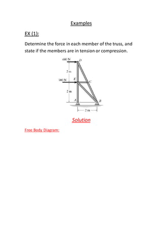
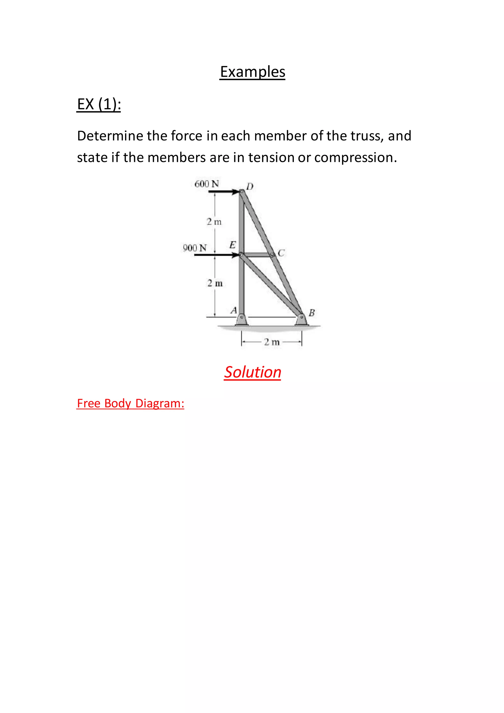
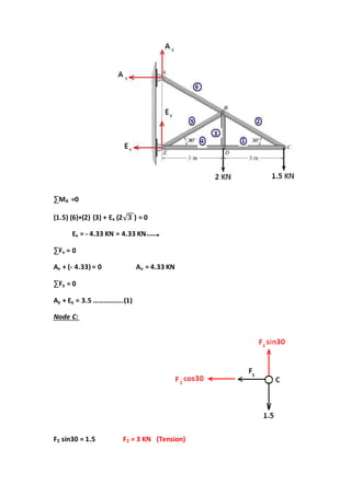
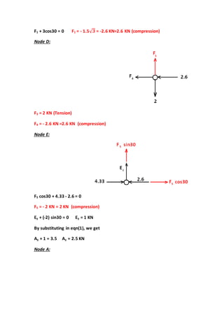
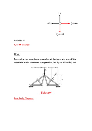
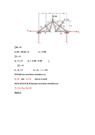
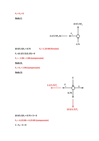
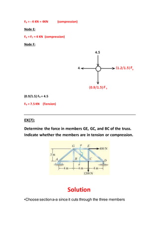
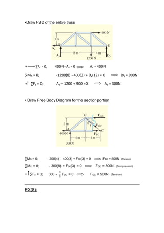
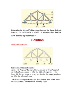
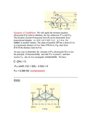
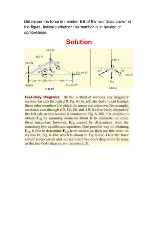
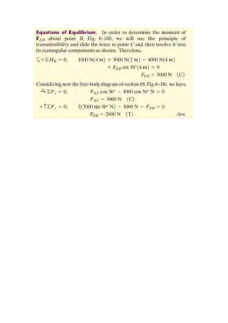

1) The documents provide examples of solving for forces in truss members by using free body diagrams and equilibrium equations. 2) The solutions involve drawing FBDs of the trusses or sections of trusses, then writing the ΣF and ΣM equations and solving the systems of equations. 3) The determined forces are then identified as either tension or compression forces in the members.


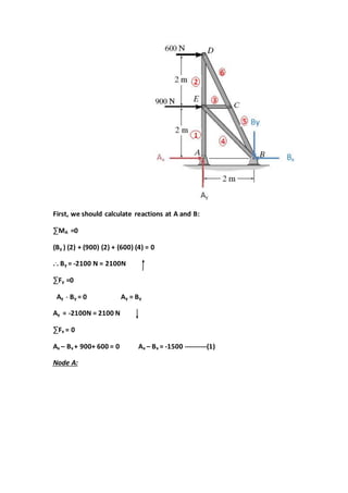
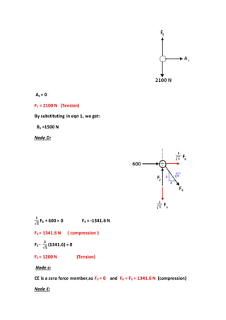
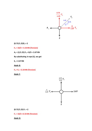
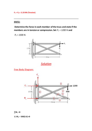
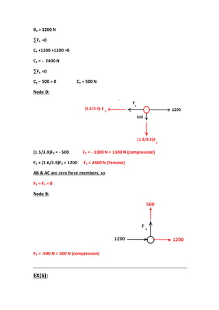
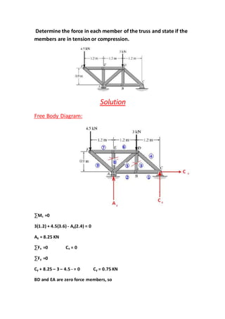
![Lecture truss [compatibility mode]](https://cdn.slidesharecdn.com/ss_thumbnails/lecturetrusscompatibilitymode-160126134009-thumbnail.jpg?width=640&height=640&fit=bounds)


