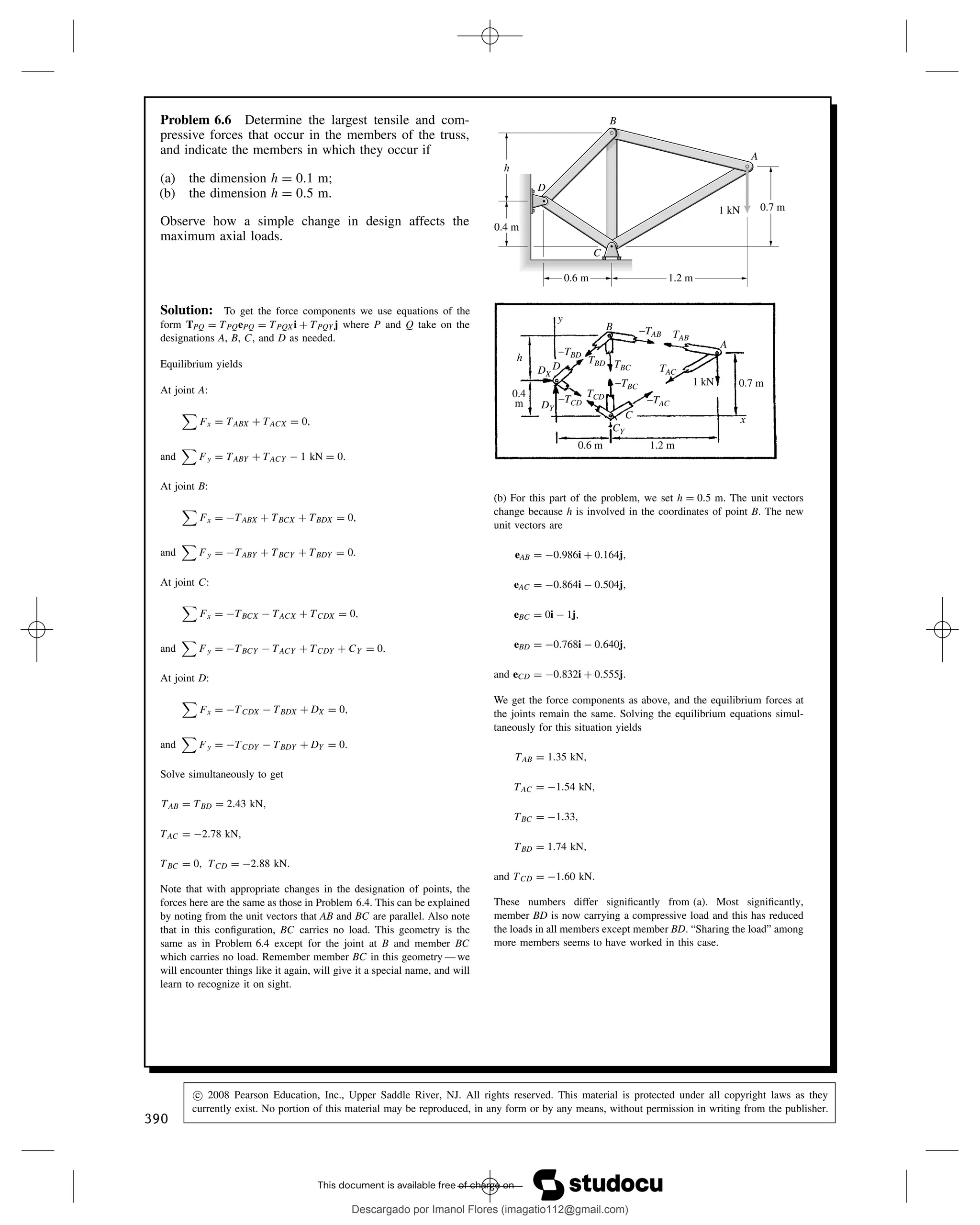
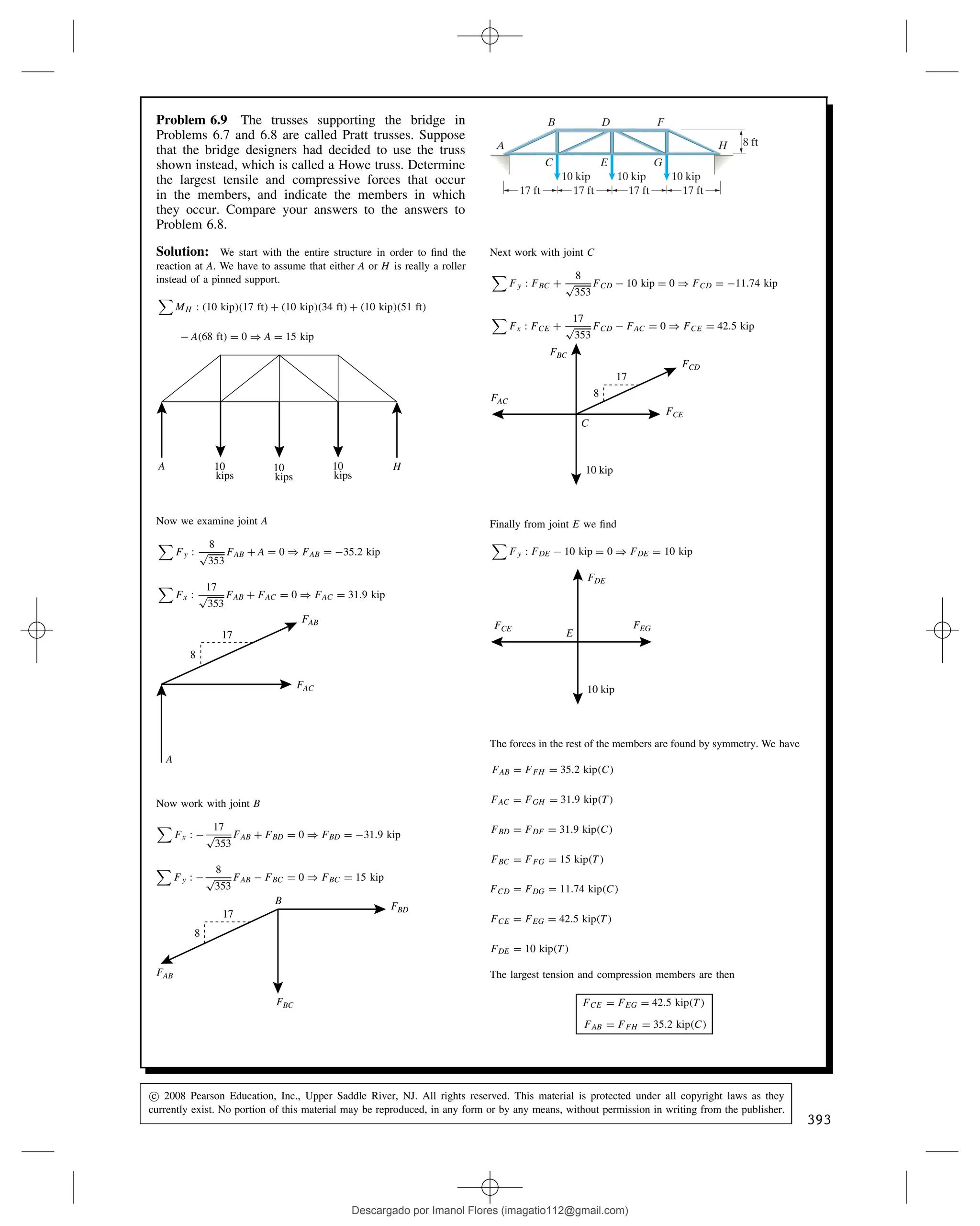
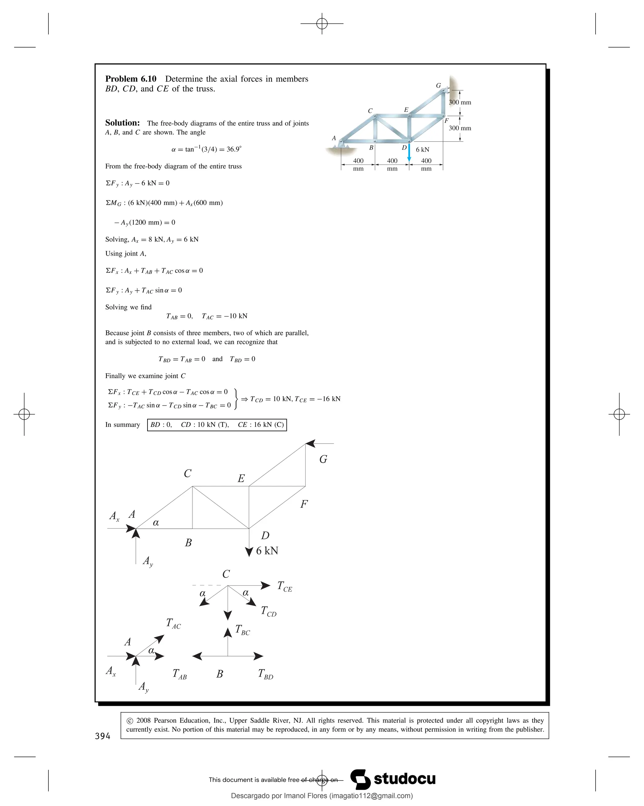
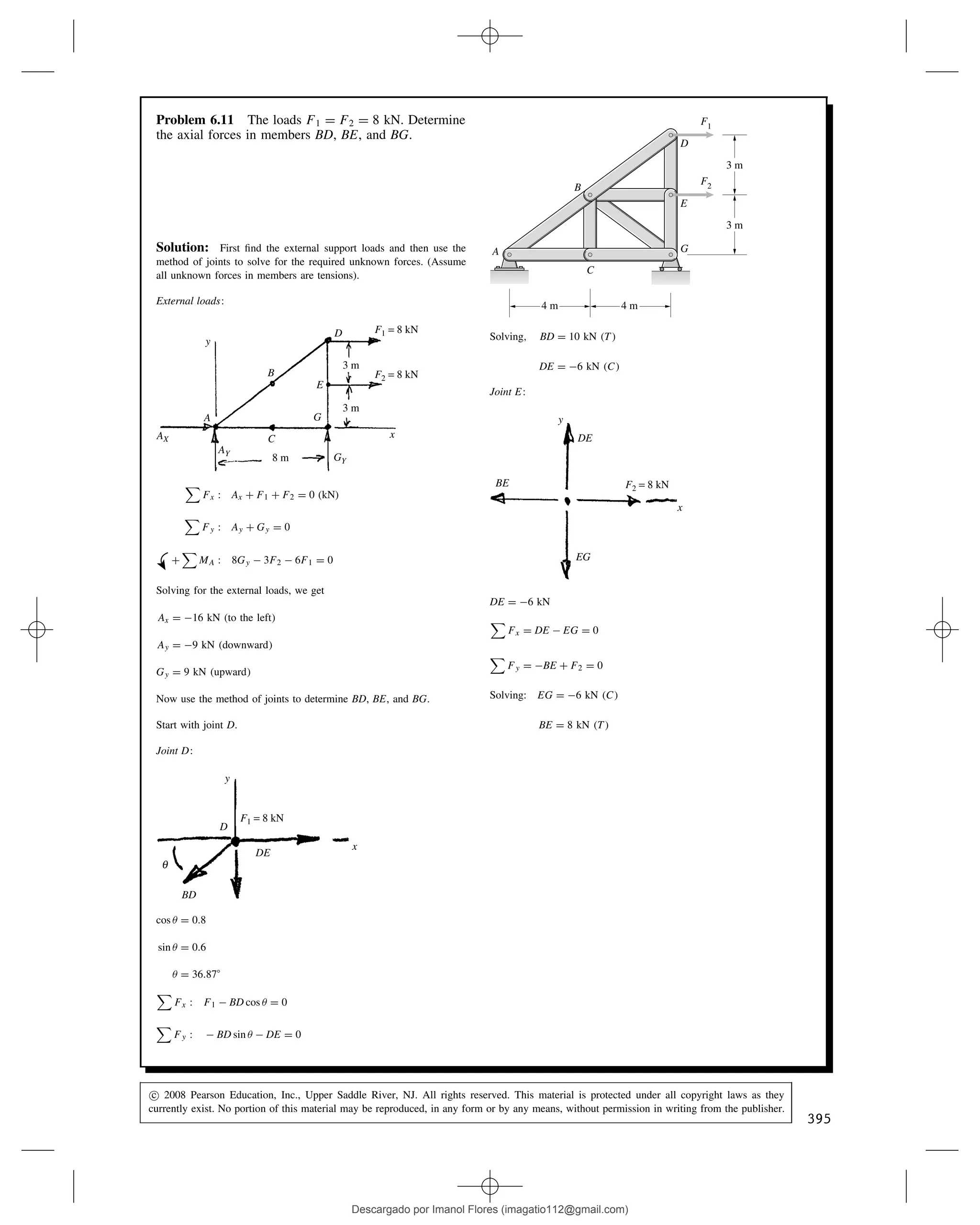
1. Studocu no está patrocinado ni avalado por ningún colegio o universidad.
Statics Bedford chap 06
Estática (Pontificia Universidad Católica del Perú)
Studocu no está patrocinado ni avalado por ningún colegio o universidad.
Statics Bedford chap 06
Estática (Pontificia Universidad Católica del Perú)
Descargado por Imanol Flores (imagatio112@gmail.com)
lOMoARcPSD|5137786
2. Problem 6.1 In Active Example 6.1, suppose that in
addition to the 2-kN downward force acting at point D,
a 2-kN downward force acts at point C. Draw a sketch of
the truss showing the new loading. Determine the axial
forces in members AB and AC of the truss.
C
5 m
5 m
A
D
B
2 kN
3 m
3 m
Solution: The new sketch, a free-body diagram of the entire truss
and a free-body diagram of the joint at A are shown. The angle ˛
between CD and BD is
˛ D tan1
⊲6/10⊳ D 31.0°
Using the entire truss, the equilibrium equations are
Fx : Ax C B D 0
Fy : Ay 2 kN 2 kN D 0
MA : ⊲2 kN⊳⊲5 m⊳ ⊲2 kN⊳⊲10 m⊳
C B⊲6 m⊳ D 0
Solving yields
Ax D 5 kN, Ay D 4 kN, B D 5 kN
Using the free-body diagram of joint A, the equilibrium equations are:
Fx : Ax C TAC cos ˛ D 0
Fy : Ay TAB TAC sin ˛ D 0
Solving yields TAB D 1 kN, TAC D 5.83 kN
Because both values are positive, we know that both are in tension
AB : 1 kN (T), AC : 5.83 kN (T)
386
c 2008 Pearson Education, Inc., Upper Saddle River, NJ. All rights reserved. This material is protected under all copyright laws as they
currently exist. No portion of this material may be reproduced, in any form or by any means, without permission in writing from the publisher.
Descargado por Imanol Flores (imagatio112@gmail.com)
lOMoARcPSD|5137786
3. Problem 6.2 Determine the axial forces in the
members of the truss and indicate whether they are in
tension (T) or compression (C).
C
800 N
0.7 m
0.7 m
A
B
0.4 m
20⬚
Solution: We start at joint A
Fx :
7
p
65
FAB C
7
p
65
FAC ⊲800 N⊳ sin 20° D 0
Fy :
4
p
65
FAB
4
p
65
FAC ⊲800 N⊳ cos 20° D 0
Solving we have FAB D 915 N, FAC D 600 N
7 7
4
4
800 N
A
FAC
FAB
20°
Next we move to joint C
Fx :
7
p
65
FAC FBC D 0 ) FBC D 521 N
C
Cy
FAC
FCB
7
4
In summary we have
FAB D 915 N⊲C⊳, FAC D 600 N⊲C⊳, FBC D 521 N⊲T⊳
Problem 6.3 Member AB of the truss is subjected to a
1000-lb tensile force. Determine the weight W and the
axial force in member AC.
A
B
W
C
60 in
60 in 60 in
Solution: Using joint A
Fx :
2
p
5
⊲1000 lb⊳
1
p
2
FAC D 0
Fy :
1
p
5
⊲1000 lb⊳
1
p
2
FAC W D 0
Solving we have FAC D 1265 lb, W D 447 lb
In summary we have
W D 447 lb, FAC D 1265 lb⊲C⊳
1000 lb
A
2
1
1
1
FAC
W
c 2008 Pearson Education, Inc., Upper Saddle River, NJ. All rights reserved. This material is protected under all copyright laws as they
currently exist. No portion of this material may be reproduced, in any form or by any means, without permission in writing from the publisher.
387
Descargado por Imanol Flores (imagatio112@gmail.com)
lOMoARcPSD|5137786
4. Problem 6.4 Determine the axial forces in members
BC and CD of the truss.
600 lb
D
E
3 ft
3 ft
3 ft
3 ft
A
C
B
Solution: The free-body diagrams for joints E, D, and C are
shown. The angle ˛ is
˛ D tan1
⊲3/4⊳ D 36.9°
Using Joint E, we have
Fx : ⊲600 lb⊳ TCE sin ˛ D 0
Fy : TCE cos ˛ TDE D 0
Using Joint D, we have
Fx : TCD TBD sin ˛ D 0
Fy : TDE TBD cos ˛ D 0
Finally, using Joint C, we have
Fx : TCD C TCD sin ˛ TAC sin ˛ D 0
Fy : TCE cos ˛ TAC cos ˛ TBC D 0
Solving these six equations yields
TCE D 1000 lb, TDE D 800 lb
TCD D 600 lb, TAC D 2000 lb
TBC D 800 lb, TBD D 1000 lb
A positive value means tension and a negative value means compres-
sion
Thus BC : 800 lb (T), CD : 600 lb (C)
388
c 2008 Pearson Education, Inc., Upper Saddle River, NJ. All rights reserved. This material is protected under all copyright laws as they
currently exist. No portion of this material may be reproduced, in any form or by any means, without permission in writing from the publisher.
Descargado por Imanol Flores (imagatio112@gmail.com)
lOMoARcPSD|5137786
5. Problem 6.5 Each suspended weight has mass m D
20 kg. Determine the axial forces in the members of
the truss and indicate whether they are in tension (T) or
compression (C).
0.32 m
0.16 m
0.16 m
0.4 m
A
B
C D
m m
Solution: Assume all bars are in tension. Start with joint D
Fy :
5
p
61
TAD 196.2 N D 0
Fx :
6
p
61
TAD TCD D 0
Solving: TAD D 306 N, TCD D 235 N
TAD
TCD
5
6
196.2 N
D
Now work with joint C
Fy :
5
p
29
TAC 196.2 N D 0
Fx :
2
p
29
TAC TBC C TCD D 0
Solving: TAC D 211 N, TBC D 313 N
TAC
5
2
196.2 N
C
TBC TCD
Finally work with joint A
Fy :
5
p
29
⊲TAB C TAC⊳
5
p
61
TAD D 0
) TAB D 423 N
T
TAB TAC
TAD
A
2
2
5 5
5
6
In summary:
TAB D 423 N⊲C⊳
TAC D 211 N⊲T⊳
TAD D 306 N⊲T⊳
TBC D 314 N⊲C⊳
TCD D 235 N⊲C⊳
c 2008 Pearson Education, Inc., Upper Saddle River, NJ. All rights reserved. This material is protected under all copyright laws as they
currently exist. No portion of this material may be reproduced, in any form or by any means, without permission in writing from the publisher.
389
Descargado por Imanol Flores (imagatio112@gmail.com)
lOMoARcPSD|5137786
6. Problem 6.6 Determine the largest tensile and com-
pressive forces that occur in the members of the truss,
and indicate the members in which they occur if
(a) the dimension h D 0.1 m;
(b) the dimension h D 0.5 m.
Observe how a simple change in design affects the
maximum axial loads.
0.6 m
0.4 m
h
1.2 m
0.7 m
1 kN
C
D
B
A
Solution: To get the force components we use equations of the
form TPQ D TPQePQ D TPQXi C TPQYj where P and Q take on the
designations A, B, C, and D as needed.
Equilibrium yields
At joint A:
Fx D TABX C TACX D 0,
and
Fy D TABY C TACY 1 kN D 0.
At joint B:
Fx D TABX C TBCX C TBDX D 0,
and
Fy D TABY C TBCY C TBDY D 0.
At joint C:
Fx D TBCX TACX C TCDX D 0,
and
Fy D TBCY TACY C TCDY C CY D 0.
At joint D:
Fx D TCDX TBDX C DX D 0,
and
Fy D TCDY TBDY C DY D 0.
Solve simultaneously to get
TAB D TBD D 2.43 kN,
TAC D 2.78 kN,
TBC D 0, TCD D 2.88 kN.
Note that with appropriate changes in the designation of points, the
forces here are the same as those in Problem 6.4. This can be explained
by noting from the unit vectors that AB and BC are parallel. Also note
that in this configuration, BC carries no load. This geometry is the
same as in Problem 6.4 except for the joint at B and member BC
which carries no load. Remember member BC in this geometry — we
will encounter things like it again, will give it a special name, and will
learn to recognize it on sight.
0.6 m 1.2 m
CY
DY
DX
TBC
−TBC
TBD
TCD
TAB
TAC
−TAB
−TAC
−TCD
−TBD
B
y
h
C
D
A
x
1 kN
0.4
m
0.7 m
(b) For this part of the problem, we set h D 0.5 m. The unit vectors
change because h is involved in the coordinates of point B. The new
unit vectors are
eAB D 0.986i C 0.164j,
eAC D 0.864i 0.504j,
eBC D 0i 1j,
eBD D 0.768i 0.640j,
and eCD D 0.832i C 0.555j.
We get the force components as above, and the equilibrium forces at
the joints remain the same. Solving the equilibrium equations simul-
taneously for this situation yields
TAB D 1.35 kN,
TAC D 1.54 kN,
TBC D 1.33,
TBD D 1.74 kN,
and TCD D 1.60 kN.
These numbers differ significantly from (a). Most significantly,
member BD is now carrying a compressive load and this has reduced
the loads in all members except member BD. “Sharing the load” among
more members seems to have worked in this case.
390
c 2008 Pearson Education, Inc., Upper Saddle River, NJ. All rights reserved. This material is protected under all copyright laws as they
currently exist. No portion of this material may be reproduced, in any form or by any means, without permission in writing from the publisher.
Descargado por Imanol Flores (imagatio112@gmail.com)
lOMoARcPSD|5137786
7. Problem 6.7 This steel truss bridge is in the Gallatin
National Forest south of Bozeman, Montana. Suppose
that one of the tandem trusses supporting the bridge is
loaded as shown. Determine the axial forces in members
AB, BC, BD, and BE.
17 ft 17 ft 17 ft 17 ft
A
B D F
H
G
E
C
8 ft
10 kip 10 kip 10 kip
Solution: We start with the entire structure in order to find the
reaction at A. We have to assume that either A or H is really a roller
instead of a pinned support.
MH : ⊲10 kip⊳⊲17 ft⊳ C ⊲10 kip⊳⊲34 ft⊳ C ⊲10 kip⊳⊲51 ft⊳
A⊲68 ft⊳ D 0 ) A D 15 kip
17 ft
A 10 kip 10 kip 10 kip H
17 ft 17 ft 17 ft
Now we examine joint A
Fy :
8
p
353
FAB C A D 0 ) FAB D 35.2 kip
17
8
A
FAB
FAC
Now work with joint C
Fy : FBC 10 kip D 0 ) FBC D 10 kip
FAC FCE
FBC
C
10 kip
Finally work with joint B
Fx :
17
p
353
FAB C
17
p
353
FBE C FBD D 0
Fy :
8
p
353
FAB
8
p
353
FBE FBC D 0
Solving we find FBD D 42.5 kip, FBE D 11.74 kip
17
8
17
8
FBE
FBC
FAB
B FBD
In Summary we have
FAB D 35.2 kip⊲C⊳, FBC D 10 kip⊲T⊳,
FBD D 42.5 kip⊲C⊳, FBE D 11.74 kip⊲T⊳
c 2008 Pearson Education, Inc., Upper Saddle River, NJ. All rights reserved. This material is protected under all copyright laws as they
currently exist. No portion of this material may be reproduced, in any form or by any means, without permission in writing from the publisher.
391
Descargado por Imanol Flores (imagatio112@gmail.com)
lOMoARcPSD|5137786
8. Problem 6.8 For the bridge truss in Problem 6.7,
determine the largest tensile and compressive forces that
occur in the members, and indicate the members in
which they occur.
Solution: Continuing the solution to Problem 6.7 will show the
largest tensile and compressive forces that occur in the structure.
Examining joint A we have
Fx :
17
p
353
FAB C FAC D 0 ) FAC D 31.9 kip
Examining joint C
Fx : FAC C FCE D 0 ) FCE D 31.9 kip
Examining joint D
Fy : FDE D 0 ) FDE D 0
D
FBD FDF
FDE
The forces in the rest of the members are found by symmetry. We have
FAB D FFH D 35.2 kip⊲C⊳
FAC D FGH D 31.9 kip⊲T⊳
FBC D FFG D 10 kip⊲T⊳
FBD D FDF D 42.5 kip⊲C⊳
FBE D FEF D 11.74 kip⊲T⊳
FCE D FEG D 31.9 kip⊲T⊳
FDE D 0
The largest tension and compression members are then
FAC D FEG D FCE D FGH D 31.9 kip⊲T⊳
FBD D FDH D 42.5 kip⊲C⊳
392
c 2008 Pearson Education, Inc., Upper Saddle River, NJ. All rights reserved. This material is protected under all copyright laws as they
currently exist. No portion of this material may be reproduced, in any form or by any means, without permission in writing from the publisher.
Descargado por Imanol Flores (imagatio112@gmail.com)
lOMoARcPSD|5137786
9. Problem 6.9 The trusses supporting the bridge in
Problems 6.7 and 6.8 are called Pratt trusses. Suppose
that the bridge designers had decided to use the truss
shown instead, which is called a Howe truss. Determine
the largest tensile and compressive forces that occur
in the members, and indicate the members in which
they occur. Compare your answers to the answers to
Problem 6.8.
17 ft 17 ft 17 ft 17 ft
A
B D F
H
G
E
C
8 ft
10 kip 10 kip 10 kip
Solution: We start with the entire structure in order to find the
reaction at A. We have to assume that either A or H is really a roller
instead of a pinned support.
MH : ⊲10 kip⊳⊲17 ft⊳ C ⊲10 kip⊳⊲34 ft⊳ C ⊲10 kip⊳⊲51 ft⊳
A⊲68 ft⊳ D 0 ) A D 15 kip
A H
10
kips
10
kips
10
kips
Now we examine joint A
Fy :
8
p
353
FAB C A D 0 ) FAB D 35.2 kip
Fx :
17
p
353
FAB C FAC D 0 ) FAC D 31.9 kip
A
FAC
FAB
17
8
Now work with joint B
Fx :
17
p
353
FAB C FBD D 0 ) FBD D 31.9 kip
Fy :
8
p
353
FAB FBC D 0 ) FBC D 15 kip
FBD
FBC
FAB
B
17
8
Next work with joint C
Fy : FBC C
8
p
353
FCD 10 kip D 0 ) FCD D 11.74 kip
Fx : FCE C
17
p
353
FCD FAC D 0 ) FCE D 42.5 kip
FCD
FBC
FCE
10 kip
FAC
C
17
8
Finally from joint E we find
Fy : FDE 10 kip D 0 ) FDE D 10 kip
E
FCE
FDE
FEG
10 kip
The forces in the rest of the members are found by symmetry. We have
FAB D FFH D 35.2 kip⊲C⊳
FAC D FGH D 31.9 kip⊲T⊳
FBD D FDF D 31.9 kip⊲C⊳
FBC D FFG D 15 kip⊲T⊳
FCD D FDG D 11.74 kip⊲C⊳
FCE D FEG D 42.5 kip⊲T⊳
FDE D 10 kip⊲T⊳
The largest tension and compression members are then
FCE D FEG D 42.5 kip⊲T⊳
FAB D FFH D 35.2 kip⊲C⊳
c 2008 Pearson Education, Inc., Upper Saddle River, NJ. All rights reserved. This material is protected under all copyright laws as they
currently exist. No portion of this material may be reproduced, in any form or by any means, without permission in writing from the publisher.
393
Descargado por Imanol Flores (imagatio112@gmail.com)
lOMoARcPSD|5137786
10. Problem 6.10 Determine the axial forces in members
BD, CD, and CE of the truss.
F
400
mm
400
mm
400
mm
300 mm
300 mm
6 kN
A
B
C
D
E
G
Solution: The free-body diagrams of the entire truss and of joints
A, B, and C are shown. The angle
˛ D tan1
⊲3/4⊳ D 36.9°
From the free-body diagram of the entire truss
Fy : Ay 6 kN D 0
MG : ⊲6 kN⊳⊲400 mm⊳ C Ax⊲600 mm⊳
Ay⊲1200 mm⊳ D 0
Solving, Ax D 8 kN, Ay D 6 kN
Using joint A,
Fx : Ax C TAB C TAC cos ˛ D 0
Fy : Ay C TAC sin ˛ D 0
Solving we find
TAB D 0, TAC D 10 kN
Because joint B consists of three members, two of which are parallel,
and is subjected to no external load, we can recognize that
TBD D TAB D 0 and TBD D 0
Finally we examine joint C
Fx : TCE C TCD cos ˛ TAC cos ˛ D 0
Fy : TAC sin ˛ TCD sin ˛ TBC D 0
) TCD D 10 kN, TCE D 16 kN
In summary BD : 0, CD : 10 kN (T), CE : 16 kN (C)
394
c 2008 Pearson Education, Inc., Upper Saddle River, NJ. All rights reserved. This material is protected under all copyright laws as they
currently exist. No portion of this material may be reproduced, in any form or by any means, without permission in writing from the publisher.
Descargado por Imanol Flores (imagatio112@gmail.com)
lOMoARcPSD|5137786
11. Problem 6.11 The loads F1 D F2 D 8 kN. Determine
the axial forces in members BD, BE, and BG.
3 m
A
B
D
E
G
F2
F1
4 m
C
4 m
3 m
Solution: First find the external support loads and then use the
method of joints to solve for the required unknown forces. (Assume
all unknown forces in members are tensions).
External loads:
y
x
B
A
E
G
GY
C
D
AX
AY
F1 = 8 kN
F2 = 8 kN
3 m
8 m
3 m
Fx : Ax C F1 C F2 D 0 (kN)
Fy : Ay C Gy D 0
C
MA : 8Gy 3F2 6F1 D 0
Solving for the external loads, we get
Ax D 16 kN ⊲to the left⊳
Ay D 9 kN ⊲downward⊳
Gy D 9 kN ⊲upward⊳
Now use the method of joints to determine BD, BE, and BG.
Start with joint D.
Joint D:
BD
DE
D
x
y
F1 = 8 kN
θ
cos D 0.8
sin D 0.6
D 36.87°
Fx : F1 BD cos D 0
Fy : BD sin DE D 0
Solving, BD D 10 kN ⊲T⊳
DE D 6 kN ⊲C⊳
Joint E:
BE
DE
EG
x
y
F2 = 8 kN
DE D 6 kN
Fx D DE EG D 0
Fy D BE C F2 D 0
Solving: EG D 6 kN ⊲C⊳
BE D 8 kN ⊲T⊳
c 2008 Pearson Education, Inc., Upper Saddle River, NJ. All rights reserved. This material is protected under all copyright laws as they
currently exist. No portion of this material may be reproduced, in any form or by any means, without permission in writing from the publisher.
395
Descargado por Imanol Flores (imagatio112@gmail.com)
lOMoARcPSD|5137786
12. 6.11 (Continued)
Joint G:
EG
y
x
CG
BG
GY
θ
⊲EG D 6 kN ⊲C⊳⊳
Gy D 9 kN
Fx : CG BG cos D 0
Fy : BG sin C EG C Gy D 0
Solving, we get
BG D 5 kN ⊲C⊳
CG D 4 kN ⊲T⊳
Thus, we have
BD D 10 kN ⊲T⊳
BE D 8 kN ⊲T⊳
BG D 5 kN ⊲C⊳
Problem 6.12 Determine the largest tensile and
compressive forces that occur in the members of the
truss, and indicate the members in which they occur if
(a) the dimension h D 5 in;
(b) the dimension h D 10 in.
Observe how a simple change in design affects the
maximum axial loads.
20 in 20 in 20 in
30⬚
800 lb
A
B
C
E
D
h
Solution: Starting at joint A
Fx :
20
p
h2 C 202
FAB FAC C ⊲800 lb⊳ sin 30° D 0
Fy :
h
p
h2 C 202
FAB ⊲800 lb⊳ cos 30° D 0
800 lb
A
20
h
FAB
FAC
Next joint B
Fx : FBD
20
p
h2 C 202
FBC C
20
p
h2 C 202
FAB D 0
Fy :
h
p
h2 C 202
FBC
h
p
h2 C 202
FAB D 0
20
h h
B
FBD
FAB
FBC
20
Finally joint C
Fx :
20
p
h2 C 202
FCD C
20
p
h2 C 202
FBC FCE C FAC D 0
Fy :
h
p
h2 C 202
FCD C
h
p
h2 C 202
FBC D 0
20
20
h h
FCD
FBC
C FAC
FCE
(a) Using h D 5 in we find:
FAB D 2860 lb⊲T⊳, FAC D 2370 lb⊲C⊳, FBD D 5540 lb⊲T⊳
FBC D 2860 lb⊲C⊳, FCD D 2860 lb⊲T⊳, FCE D 7910 lb⊲C⊳
)
FBD D 5540 lb⊲T⊳
FCE D 7910 lb⊲C⊳
(b) Using h D 10 in we find:
FAB D 1549 lb⊲T⊳, FAC D 986 lb⊲C⊳, FBD D 2770 lb⊲T⊳
FBC D 1549 lb⊲C⊳, FCD D 1549 lb⊲T⊳, FCE D 3760 lb⊲C⊳
)
FBD D 2770 lb⊲T⊳
FCE D 3760 lb⊲C⊳
396
c 2008 Pearson Education, Inc., Upper Saddle River, NJ. All rights reserved. This material is protected under all copyright laws as they
currently exist. No portion of this material may be reproduced, in any form or by any means, without permission in writing from the publisher.
Descargado por Imanol Flores (imagatio112@gmail.com)
lOMoARcPSD|5137786
13. Problem 6.13 The truss supports loads at C and E.
If F D 3 kN, what are the axial forces in members BC
and BE? A B
C
D
E
G
1 m
F
2F
1 m 1 m 1 m
Solution: The moment about A is
MA D 1F 4F C 3G D 0,
from which G D
5
3
F D 5 kN. The sums of forces:
FY D AY 3F C G D 0,
from which AY D
4
3
F D 4 kN.
FX D AX D 0,
from which AX D 0. The interior angles GDE, EBC are 45°,
from which sin ˛ D cos ˛ D
1
p
2
.
Denote the axial force in a member joining I, K by IK.
(1) Joint G:
Fy D
DG
p
2
C G D 0,
from which
DG D
p
2G D
5
p
2
3
F D 5
p
2 kN ⊲C⊳.
Fx D
DG
p
2
EG D 0,
from which
EG D
DG
p
2
D
5
3
F D 5kN ⊲T⊳.
(2) Joint D:
Fy D DE
DG
p
2
D 0,
from which
DE D
5
3
F D 5 kN ⊲T⊳.
Fx D BD C
DG
p
2
D 0,
1 m
1 m 1 m 1 m
AY
AY
AX
F G
2F
DG
DE
BD DG
EG
AC
AB AC
BC
CE
F
G
Joint G
Joint A Joint C
Joint D Joint E
45°
45°
45°
45°
45°
CE EG
DE
BE
from which
BD D
5
3
F D 5 kN ⊲C⊳.
(3) Joint E:
Fy D
BE
p
2
2F C DE D 0,
from which BE D 2
p
2F
p
2DE D
p
2
3
F D
p
2 kN ⊲T⊳.
Fx D CE
BE
p
2
C EG D 0,
from which
CE D EG
BE
p
2
D
4
3
F D 4 kN ⊲T⊳.
c 2008 Pearson Education, Inc., Upper Saddle River, NJ. All rights reserved. This material is protected under all copyright laws as they
currently exist. No portion of this material may be reproduced, in any form or by any means, without permission in writing from the publisher.
397
Descargado por Imanol Flores (imagatio112@gmail.com)
lOMoARcPSD|5137786
14. 6.13 (Continued)
(4) Joint A:
Fy D Ay
AC
p
2
D 0,
from which AC D
4
p
2
3
F D 4
p
2 kN ⊲T⊳.
Fx D AB C
AC
p
2
D 0,
from which AB D
4
3
F D 4 kN ⊲C⊳.
(5) Joint C:
Fy D BC C
AC
p
2
F D 0,
from which BC D F
AC
p
2
D
1
3
F D 1 kN ⊲C⊳.
Problem 6.14 If you don’t want the members of the
truss to be subjected to an axial load (tension or compres-
sion) greater than 20 kN, what is the largest acceptable
magnitude of the downward force F? 12 m
3 m
A
F
C
D
B
4 m
Solution: Start with joint A
Fx : FAB cos 36.9° FAC sin 30.5° D 0
Fy : FAB sin 36.9° FAC cos 30.5° F D 0
A
36.9°
30.5°
F
FAB
FAC
Now work with joint C
Fx : FCD FBC sin 36.9° C FAC sin 30.5° D 0
Fy : FBC cos 36.9° C FAC cos 30.5° D 0
36.9°
30.5°
C
FCD
FBC FAC
Finally examine joint D
Fy : FBD D 0
FBD
D
Dx FCD
Solving we find
FAB D 1.32F, FAC D 2.08F, FCD D 2.4F,
FBC D 2.24F, FBD D 0
The critical member is CD. Thus
2.4F D 20 kN ) F D 8.33 kN
398
c 2008 Pearson Education, Inc., Upper Saddle River, NJ. All rights reserved. This material is protected under all copyright laws as they
currently exist. No portion of this material may be reproduced, in any form or by any means, without permission in writing from the publisher.
Descargado por Imanol Flores (imagatio112@gmail.com)
lOMoARcPSD|5137786
15. Problem 6.15 The truss is a preliminary design for a
structure to attach one end of a stretcher to a rescue
helicopter. Based on dynamic simulations, the design
engineer estimates that the downward forces the stretcher
will exert will be no greater than 1.6 kN at A and at B.
What are the resulting axial forces in members CF, DF,
and FG?
300
mm
290
mm
390
mm
200 mm
480 mm
150 mm
A
B
D
C
G
F
E
Solution: Start with joint C
Fy :
48
p
3825
FCF 1.6 kN D 0 ) FCF D 2.06 kN
FCF
39
48
C
1.6 kN
FCD
Now use joint F
Fx :
59
p
3706
FFG
29
p
3145
FDF C
39
p
3825
FCF D 0
Fy :
15
p
3706
FFG
48
p
3145
FDF
48
p
3825
FCF D 0
Solving we find FDF D 1.286 kN, FCF D 2.03 kN
FDF
FCF
FFG
59
15
F
39
48
48
29
In Summary
FCF D 2.06 kN⊲T⊳, FDF D 1.29 kN⊲C⊳, FCF D 2.03 kN⊲T⊳
c 2008 Pearson Education, Inc., Upper Saddle River, NJ. All rights reserved. This material is protected under all copyright laws as they
currently exist. No portion of this material may be reproduced, in any form or by any means, without permission in writing from the publisher.
399
Descargado por Imanol Flores (imagatio112@gmail.com)
lOMoARcPSD|5137786
16. Problem 6.16 Upon learning of an upgrade in the heli-
copter’s engine, the engineer designing the truss does
new simulations and concludes that the downward forces
the stretcher will exert at A and at B may be as large as
1.8 kN. What are the resulting axial forces in members
DE, DF, and DG?
Solution: Assume all bars are in tension.
Start at joint C
Fy :
16
p
425
TCF 1.8 kN D 0 ) TCF D 2.32 kN
Fx :
13
p
425
TCF TCD D 0 ) TCD D 1.463 kN
C
TCF
TCD
13
16
1.8 kN
Next work with joint F
Fx :
59
p
3706
TFG
29
p
3145
TDF C
13
p
425
TCF D 0
Fy :
15
p
3706
TFG
48
p
3145
TDF
48
p
425
TCF D 0
Solving TDF D 5.09 kN, TFG D 4.23 kN
TFG F
TDF
TCF
29
48
13
16
15
59
Next work with joint B
Fx :
3
p
13
TBE D 0 ) TBE D 0
Fy :
2
p
13
TBE C TBD 1.8 kN D 0 ) TBD D 1.8 kN
B
TBD
TBE
3
2
1.8 kN
Finally work with joint D
Fx : TDE
10
p
541
TDG C
29
p
3145
TDF C TCD D 0
Fy :
21
p
541
TDG C
48
p
3145
TDF TBD D 0
Solving: TDG D 6.82 kN, TDE D 7.03 kN
TDE TCD
TBD
TDG
D
TDF
21
10
48
29
In summary:
TDE D 7.03 kN⊲C⊳, TDF D 5.09 kN⊲C⊳, TDG D 6.82 kN⊲T⊳
400
c 2008 Pearson Education, Inc., Upper Saddle River, NJ. All rights reserved. This material is protected under all copyright laws as they
currently exist. No portion of this material may be reproduced, in any form or by any means, without permission in writing from the publisher.
Descargado por Imanol Flores (imagatio112@gmail.com)
lOMoARcPSD|5137786
17. Problem 6.17 Determine the axial forces in the
members in terms of the weight W.
A
B E
D
C
1 m
1 m
0.8 m 0.8 m 0.8 m
W
Solution: Denote the axial force in a member joining two points
I, K by IK. The angle between member DE and the positive x axis
is ˛ D tan1 0.8 D 38.66°. The angle formed by member DB with the
positive x axis is 90° C ˛. The angle formed by member AB with the
positive x axis is ˛.
Joint E:
Fy D DE cos ˛ W D 0,
from which DE D 1.28W ⊲C⊳ .
Fy D BE DE sin ˛ D 0,
from which BE D 0.8W ⊲T⊳
Joint D:
Fx D DE cos ˛ C BD cos ˛ CD cos ˛ D 0,
from which BD CD D DE.
Fy D BD sin ˛ C DE sin ˛ CD sin ˛ D 0,
from which BD C CD D DE.
Solving these two equations in two unknowns:
CD D DE D 1.28W ⊲C⊳ , BD D 0
Joint B:
Fx D BE AB sin ˛ BD sin ˛ D 0,
from which AB D
BE
sin ˛
D 1.28W⊲T⊳
Fy D AB cos ˛ BC D 0,
from which BC D AB cos ˛ D W⊲C⊳
c 2008 Pearson Education, Inc., Upper Saddle River, NJ. All rights reserved. This material is protected under all copyright laws as they
currently exist. No portion of this material may be reproduced, in any form or by any means, without permission in writing from the publisher.
401
Descargado por Imanol Flores (imagatio112@gmail.com)
lOMoARcPSD|5137786
18. Problem 6.18 The lengths of the members of the truss
are shown. The mass of the suspended crate is 900 kg.
Determine the axial forces in the members.
12 m
12 m
5 m
13 m
13 m
C
D
B
A
40⬚
Solution: Start with joint A
Fx : FAB cos 40° FAC sin 27.4° D 0
Fy : FAB sin 40° FAC cos 27.4° ⊲900 kg⊳⊲9.81 m/s2
⊳ D 0
A
FAC
FAB
8829 N
40°
27.4°
Next work with joint C
Fx : FCD cos 40° FBC cos 50° C FAC sin 27.4° D 0
Fy : FCD sin 40° C FBC sin 50° C FAC cos 27.4° D 0
27.4°
50°
40°
FAC
FCD
C
FBC
Finally work with joint B
Fy : FAB cos 50° FBC sin 50° FBD cos 27.4° D 0
50°
50°
27.4°
FAB
FBC
FBD
T B
Solving we find
FAB D 10.56 kN D 10.56 kN⊲T⊳
FAC D 17.58 kN D 17.58 kN⊲C⊳
FCD D 16.23 kN D 16.23 kN⊲C⊳
FBC D 6.76 kN D 6.76 kN⊲T⊳
FBD D 1.807 kN D 1.807 kN⊲T⊳
402
c 2008 Pearson Education, Inc., Upper Saddle River, NJ. All rights reserved. This material is protected under all copyright laws as they
currently exist. No portion of this material may be reproduced, in any form or by any means, without permission in writing from the publisher.
Descargado por Imanol Flores (imagatio112@gmail.com)
lOMoARcPSD|5137786
19. Problem 6.19 The loads F1 D 600 lb and F2 D
300 lb. Determine the axial forces in members AE, BD,
and CD.
F2
F1
D
A
B
C
4 ft
3 ft
G
E
6 ft
4 ft
Solution: The reaction at E is determined by the sum of the
moments about G:
MG D C6E 4F1 8F2 D 0,
from which
E D
4F1 C 8F2
6
D 800 lb.
The interior angle EAG is
˛ D tan1
6
8
D 36.87°.
From similar triangles this is also the value of the interior angles ACB,
CBD, and CGD. Method of joints: Denote the axial force in a member
joining two points I, K by IK.
Joint E:
Fy D E C AE D 0,
from which AE D E D 800 lb ⊲C⊳ .
Fy D EG D 0,
from which EG D 0.
Joint A:
Fy D AE AC cos ˛ D 0,
from which AC D
AE
0.8
D 1000 lb⊲T⊳.
Fy D AC sin ˛ C AB D 0,
from which AB D AC⊲0.6⊳ D 600 lb⊲C⊳.
Joint B:
Fy D BD sin ˛ AB F1 D 0,
GX
GY
6 ft
4 ft 4 ft
F1
F2
E
EG
E AE AE
AC AB
BD
BC AB
DG
CD
F2 F1
BD
α
α
α
Joint E Joint A Joint B Joint D
from which BD D
F2 C AB
0.6
D
300
0.6
D 500 lb⊲C⊳ .
Fx D BC BD cos ˛ D 0,
from which BC D BD⊲0.8⊳ D 400 lb⊲T⊳.
Joint D:
Fy D BD sin ˛ CD F1 D 0,
from which CD D F1 BD⊲0.6⊳ D 300 lb⊲C⊳
c 2008 Pearson Education, Inc., Upper Saddle River, NJ. All rights reserved. This material is protected under all copyright laws as they
currently exist. No portion of this material may be reproduced, in any form or by any means, without permission in writing from the publisher.
403
Descargado por Imanol Flores (imagatio112@gmail.com)
lOMoARcPSD|5137786
20. Problem 6.20 Consider the truss in Problem 6.19. The
loads F1 D 450 lb and F2 D 150 lb. Determine the axial
forces in members AB, AC, and BC.
Solution: From the solution to Problem 6.19 the angle ˛ D 36.87°
and the reaction at E is E D
4F1 C 8F2
6
D 500 lb. Denote the axial
force in a member joining two points I, K by IK.
Joint E:
Fy D EG D 0.
Fx D AE C E D 0,
from which AE D E D 500 lb⊲C⊳.
Joint A:
Fx D AE AC cos ˛ D 0,
from which AC D
AE
0.8
D 625 lb⊲T⊳ .
Fy D AC sin ˛ C AB D 0,
from which AB D AC⊲0.6⊳ D 375 lb⊲C⊳
Joint B:
Fy D BD sin ˛ F2 AB D 0,
from which BD D
F2 C AB
0.6
D 375 lb⊲C⊳
Fx D BC BD cos ˛ D 0,
from which BC D BD⊲0.8⊳ D 300 lb⊲T⊳
EG
E AE AE
BC AB
BD
AB
AC
Joint E Joint A Joint B
F2
α
α
404
c 2008 Pearson Education, Inc., Upper Saddle River, NJ. All rights reserved. This material is protected under all copyright laws as they
currently exist. No portion of this material may be reproduced, in any form or by any means, without permission in writing from the publisher.
Descargado por Imanol Flores (imagatio112@gmail.com)
lOMoARcPSD|5137786
21. Problem 6.21 Determine the axial forces in members
BD, CD, and CE of the truss.
C E
G
F
D
H
A
B
4 ft
4 ft
4 ft
4 ft
4 ft
12 kip
Solution: The free-body diagrams for the entire truss as well as
for joints A, B and C are shown.
From the entire truss:
Fx : Ax D 0
FH : ⊲12 kip⊳⊲8 ft⊳ Ay⊲12 ft⊳ D 0
Solving, yields Ax D 0, Ay D 8 kip
From joint A:
Fx : Ax C TAD cos 45° D 0
Fy : Ay C TAB C TAD sin 45° D 0
Solving yields TAB D 8 kip, TAD D 0
From joint B:
Fx : TBD C TBC cos 45° D 0
Fy : TBC C sin 45° TAB D 0
Solving yields TBD D 8 kip, TBC D 11.3 kip
From joint C:
Fx : TCE TBC cos 45° D 0
Fy : TBC sin 45° TCD D 0
Solving yields TCD D 8 kip, TCE D 8 kip
Thus we have
BC : 11.3 kip (C), CD : 8 kip (T), CE : 8 kip (C)
c 2008 Pearson Education, Inc., Upper Saddle River, NJ. All rights reserved. This material is protected under all copyright laws as they
currently exist. No portion of this material may be reproduced, in any form or by any means, without permission in writing from the publisher.
405
Descargado por Imanol Flores (imagatio112@gmail.com)
lOMoARcPSD|5137786
22. Problem 6.22 The Warren truss supporting the
walkway is designed to support vertical 50-kN loads at
B, D, F, and H. If the truss is subjected to these loads,
what are the resulting axial forces in members BC, CD,
and CE?
6 m
6 m
6 m
6 m
A C E G I
B D F H
2 m
Solution: Assume vertical loads at A and I Find the external loads
at A and I, then use the method of joints to work through the structure
to the members needed.
3 m 3 m
6 m 6 m 6 m
50 kN 50 kN 50 kN 50 kN
x
AY IY
Fy : Ay C Iy 4⊲50⊳ D 0 (kN)
MA : 3⊲50⊳ 9⊲50⊳ 15⊲50⊳ 21⊲50⊳ C 24 Iy D 0
Solving Ay D 100 kN
Iy D 100 kN
Joint A:
y
x
AB
AC
A
AY
θ
tan D 2
3
D 33.69°
Fx : AB cos C AC D 0
Fy : AB sin C Ay D 0
Solving, AB D 180.3 kN ⊲C⊳
AC D 150 kN ⊲T⊳
Joint B:
50 kN
BD
BC
AB
y
B
x
θ θ
AB D 180.3 kN
D 33.69°
Fx : BC cos C BD AB cos D 0
Fy : 50 AB sin BC sin D 0
Solving, BC D 90.1 kN ⊲T⊳
BD D 225 kN ⊲C⊳
Joint C:
BC
AC CE
CD
y
C
θ θ
x
D 33.69°
AC D 150 kN ⊲T⊳
BC D 90.1 kN ⊲T⊳
Fx : CE AC C CD cos BC cos D 0
Fy : CD sin C BC sin D 0
Solving,
CE D 300 kN ⊲T⊳
CD D 90.1 kN ⊲C⊳
Hence BC D 90.1 kN ⊲T⊳
CD D 90.1 kN ⊲C⊳
CE D 300 kN ⊲T⊳
406
c 2008 Pearson Education, Inc., Upper Saddle River, NJ. All rights reserved. This material is protected under all copyright laws as they
currently exist. No portion of this material may be reproduced, in any form or by any means, without permission in writing from the publisher.
Descargado por Imanol Flores (imagatio112@gmail.com)
lOMoARcPSD|5137786
23. Problem 6.23 For the Warren truss in Problem 6.22,
determine the axial forces in members DF, EF, and FG.
Solution: In the solution to Problem 6.22, we solved for the forces
in AB, AC, BC, BD, CD, and CE. Let us continue the process. We
ended with Joint C. Let us continue with Joint D.
Joint D:
D
BD
CD DE
θ θ
DF
x
y
50 kN
D 33.69°
BD D 225 kN ⊲C⊳
CD D 90.1 kN ⊲C⊳
Fx : DF BD C DE cos CD cos D 0
Fy : 50 CD sin DE sin D 0
Solving, DF D 300 kN ⊲C⊳
DE D 0
At this point, we have solved half of a symmetric truss with a
symmetric load. We could use symmetry to determine the loads in
the remaining members. We will continue, and use symmetry as a
check.
Joint E:
CE E EG
x
y
DE EF
θ θ
D 33.69°
CE D 300 kN ⊲T⊳
DE D 0
Fx : EG CE C EF cos DE cos D 0
Fy : DE sin C EF sin D 0
Solving, we get
EF D 0
EG D 300 kN ⊲T⊳
Note: The results are symmetric to this point!
Joint F:
50 kN
EF FG
DF
F FH
x
y
θ θ
D 33.69°
DF D 300 kN ⊲C⊳
EF D 0
Fx : FH DF C FG cos EF cos D 0
Fy : 50 EF sin FG sin D 0
Solving: FH D 225 kN ⊲C⊳
FG D 90.1 kN ⊲C⊳
Thus, we have
DF D 300 kN ⊲C⊳
EF D 0
FG D 90.1 kN ⊲C⊳
Note-symmetry holds!
c 2008 Pearson Education, Inc., Upper Saddle River, NJ. All rights reserved. This material is protected under all copyright laws as they
currently exist. No portion of this material may be reproduced, in any form or by any means, without permission in writing from the publisher.
407
Descargado por Imanol Flores (imagatio112@gmail.com)
lOMoARcPSD|5137786
24. Problem 6.24 The Pratt bridge truss supports five
forces (F D 300 kN). The dimension L D 8 m. Deter-
mine the axial forces in members BC, BI, and BJ.
A
B C D E G
I J K L M
H
L
L
L L L L L L
F F F F F
L
L
Solution: Find support reactions at A and H. From the free body
diagram,
Fx D AX D 0,
Fy D AY C HY 5⊲300⊳ D 0,
and
MA D 6⊲8⊳HY 300⊲8 C 16 C 24 C 32 C 40⊳ D 0.
From these equations, AY D HY D 750 kN.
From the geometry, the angle D 45°
Joint A: From the free body diagram,
Fx D AX C TAB cos C TAI D 0,
Fy D TAB sin C AY D 0.
From these equations,
TAB D 1061 kN
and TAI D 750 kN.
Joint I: From the free body diagram,
Fx D TIJ TAI D 0,
Fy D TBI 300 D 0.
From these equations,
TBI D 300 kN
and TIJ D 750 kN.
Joint B: From the free body diagram,
Fx D TBC C TBJ cos TAB cos D 0,
Fy D TBI TBJ sin TAB sin D 0.
From these equations,
TBC D 1200 kN
and TBJ D 636 kN.
B G
I J K L M H
L L L L L L
L
F F F F F
HY
AY
L = 8 m F = 300 kN
AY
A I
y
x
x
x
y
TAI
TAB TBI
TBC
TBJ
TBI
TAB
TIJ
TAI
θ
θ
θ θ
F
Joint B
Joint A Joint I
y
A
8 8 8 8 8 8
408
c 2008 Pearson Education, Inc., Upper Saddle River, NJ. All rights reserved. This material is protected under all copyright laws as they
currently exist. No portion of this material may be reproduced, in any form or by any means, without permission in writing from the publisher.
Descargado por Imanol Flores (imagatio112@gmail.com)
lOMoARcPSD|5137786
25. Problem 6.25 For the roof truss shown, determine the
axial forces in members AD, BD, DE, and DG. Model
the supports at A and I as roller supports.
A
B
C F
H
I
E
3 m 3 m 3 m 3 m 3 m 3 m
D G
6 kN
6 kN
8 kN 8 kN
10 kN
3.6 m
Solution: Use the whole structure to find the reaction at A.
MI : ⊲6 kN⊳⊲3 m⊳ C ⊲8 kN⊳⊲6 m⊳ C ⊲10 kN⊳⊲9 m⊳
C ⊲8 kN⊳⊲12 m⊳ C ⊲6 kN⊳⊲15 m⊳
C A⊲18 m⊳ D 0 ) A D 19 kN
6 kN 8 kN
10 kN
8 kN
6 kN
I
A
Now work with joint A
Fy : FAB sin 21.8° C A D 0 ) FAB D 51.2 kN
Fx : FAD C FAB cos 21.8° D 0 ) FAD D 47.5 kN
A
A
FAB
FAD
21.8°
Next use joint B
Fx : ⊲FAB C FBC C FBD⊳ cos 21.8° D 0
Fy : ⊲FAB C FBC FBD⊳ sin 21.8° ⊲6 kN⊳ D 0
Solving: FBC D 43.1 kN, FBD D 8.08 kN
6 kN
B
FBC
FBD
FAB
Next go to joint C
Fy : ⊲8 kN⊳ FCD C ⊲FCE FBC⊳ sin 21.8° D 0
Fx : ⊲FCE FBC⊳ cos 21.8° D 0
Solving: FCD D 8 kN, FCE D 43.1 kN
8 kN
C
FCD
FCD
FBC
Finally examine joint D
Fx : FAD C FDG FBD cos 21.8° C FDE cos 50.19° D 0
Fy : FBD sin 21.8° C FCD C FDE sin 50.19° D 0
Solving: FDE D 14.3 kN, FDG D 30.8 kN
D
FCD
FDE
FDG
FAD
FBD
50.19°
In Summary
FAD D 47.5 kN⊲T⊳, FBD D 8.08 kN⊲C⊳,
FDE D 14.32 kN⊲T⊳, FDG D 30.8 kN⊲T⊳
c 2008 Pearson Education, Inc., Upper Saddle River, NJ. All rights reserved. This material is protected under all copyright laws as they
currently exist. No portion of this material may be reproduced, in any form or by any means, without permission in writing from the publisher.
409
Descargado por Imanol Flores (imagatio112@gmail.com)
lOMoARcPSD|5137786
26. Problem 6.26 The Howe truss helps support a roof.
Model the supports at A and G as roller supports. Deter-
mine the axial forces in members AB, BC, and CD.
4 ft 4 ft 4 ft 4 ft 4 ft 4 ft
800 lb
8 ft
A
B
C
G
F
E
D
H I J K L
600 lb
600 lb
400 lb
400 lb
Solution: The strategy is to proceed from end A, choosing joints
with only one unknown axial force in the x- and/or y-direction, if
possible, and if not, establish simultaneous conditions in the unknowns.
The interior angles HIB and HJC differ. The pitch angle is
˛Pitch D tan1
8
12
D 33.7°.
The length of the vertical members:
BH D 4
8
12
D 2.6667 ft,
from which the angle
˛HIB D tan1
2.6667
4
D 33.7°.
CI D 8
8
12
D 5.3333 ft,
from which the angle
˛IJC D tan1
5.333
4
D 53.1°.
The moment about G:
MG D ⊲4 C 20⊳⊲400⊳ C ⊲8 C 16⊳⊲600⊳ C ⊲12⊳⊲800⊳ 24A D 0,
from which A D
33600
24
D 1400 lb. Check: The total load is 2800 lb.
From left-right symmetry each support A, G supports half the total
load. check.
The method of joints: Denote the axial force in a member joining two
points I, K by IK.
Joint A:
Fy D AB sin ˛P C 1400 D 0,
from which AB D
1400
sin ˛p
D 2523.9 lb ⊲C⊳
Fx D AB cos ˛Pitch C AH D 0,
from which AH D ⊲2523.9⊳⊲0.8321⊳ D 2100 lb ⊲T⊳
400 lb
600 lb
800 lb
600 lb
400 lb
A G
4 ft 4 ft 4 ft 4 ft 4 ft 4 ft
AB
AH
CD
CI CJ
BC
BI
HI IJ
CI
BC
BH
AH AB
BH BI
HI
1400 lb
400 lb
αPitch
αPitch
αPitch αIJC
αPitch αPitch
Joint A
Joint I Joint C
Joint H Joint B
600 lb
Joint H :
Fy D BH D 0, or, BH D 0.
Fx D AH C HI D 0,
from which HI D 2100 lb ⊲T⊳
Joint B:
Fx D AB cos ˛Pitch C BC cos ˛Pitch
C BI cos ˛Pitch D 0,
from which BC C BI D AB
410
c 2008 Pearson Education, Inc., Upper Saddle River, NJ. All rights reserved. This material is protected under all copyright laws as they
currently exist. No portion of this material may be reproduced, in any form or by any means, without permission in writing from the publisher.
Descargado por Imanol Flores (imagatio112@gmail.com)
lOMoARcPSD|5137786
27. 6.26 (Continued)
Fy D 400 AB sin ˛Pitch C BC sin ˛Pitch
BI sin ˛Pitch D 0,
from which BC BI D AB C
400
sin ˛Pitch
.
Solve the two simultaneous equations in unknowns BC, BI:
BI D
400
2 sin ˛Pitch
D 360.56 lb ⊲C⊳,
and BC D AB BI D 2163.3 lb ⊲C⊳
Joint I :
Fx D BI cos ˛Pitch HI C IJ D 0,
from which IJ D 1800 lb ⊲T⊳
Fy D CBI sin ˛Pitch C CI D 0,
from which CI D 200 lb (T)
Joint C:
Fx D BC cos ˛Pitch C CD cos ˛Pitch C CJ cos ˛IJC D 0,
from which CD⊲0.8321⊳ C CJ⊲0.6⊳ D 1800
Fy D 600 CI BC sin ˛Pitch C CD sin ˛Pitch
CJ sin ˛IJC D 0,
from which CD⊲0.5547⊳ CJ⊲0.8⊳ D 400
Solve the two simultaneous equations to obtain CJ D 666.67 lb ⊲C⊳,
and CD D 1682.57 lb ⊲C⊳
c 2008 Pearson Education, Inc., Upper Saddle River, NJ. All rights reserved. This material is protected under all copyright laws as they
currently exist. No portion of this material may be reproduced, in any form or by any means, without permission in writing from the publisher.
411
Descargado por Imanol Flores (imagatio112@gmail.com)
lOMoARcPSD|5137786
28. Problem 6.27 The plane truss forms part of the
supports of a crane on an offshore oil platform. The
crane exerts vertical 75-kN forces on the truss at B, C,
and D. You can model the support at A as a pin support
and model the support at E as a roller support that can
exert a force normal to the dashed line but cannot exert
a force parallel to it. The angle ˛ D 45°. Determine the
axial forces in the members of the truss.
3.4 m
3.4 m 3.4 m
3.4 m
1.8 m
2.2 m A E
F G H
C
D
B
α
Solution: The included angles
D tan1
4
3.4
D 49.64°,
ˇ D tan1
2.2
3.4
D 32.91°,
D tan1
1.8
3.4
D 27.9°.
The complete structure as a free body: The sum of the moments about
A is
MA D ⊲75⊳⊲3.4⊳⊲1 C 2 C 3⊳ C ⊲4⊳⊲3.4⊳Ey D 0.
with this relation and the fact that Ex cos 45° C Ey cos 45° D 0, we
obtain Ex D 112.5 kN and Ey D 112.5 kN. From
FA
x D Ax C Ex D 0, AX D EX D 112.5 kN.
FA
y D Ay 3⊲75⊳ C Ey D 0,
from which Ay D 112.5 kN. Thus the reactions at A and E are symmet-
rical about the truss center, which suggests that symmetrical truss
members have equal axial forces.
The method of joints: Denote the axial force in a member joining two
points I, K by IK.
Joint A:
Fx D AB cos C Ax C AF cos ˇ D 0,
Fy D AB sin C Ay C AF sin ˇ D 0,
from which two simultaneous equations are obtained.
Solve: AF D 44.67 kN ⊲C⊳ ,
and AB D 115.8 kN ⊲C⊳
Joint E:
Fy D DE cos C Ex EH cos ˇ D 0.
Fy D DE sin C Ey C EH sin ˇ D 0,
from which two simultaneous equations are obtained.
AX
AX
AY EY
EX
AY
EY
EX
75 kN 75 kN 75 kN
3.4
m
3.4
m
3.4
m
3.4
m
AB
AB
BF
EH
AF
γ
γ γ
θ θ
γ
β β
β
β
DE BF
AF
FG GH
DH
EH
BG DG DH
CG
CD
BC
DE
BC
75 kN 75 kN 75 kN
CD
Joint A Joint E Joint F
Joint B Joint D Joint C
Joint H
Solve: EH D 44.67 kN⊲C⊳ ,
and DE D 115.8 kN⊲C⊳
Joint F:
Fx D AF cos ˇ C FG D 0,
from which FG D 37.5 kN ⊲C⊳
Fy D AF sin ˇ C BF D 0,
from which BF D 24.26 kN ⊲C⊳
Joint H:
Fx D EH cos ˇ GH D 0,
412
c 2008 Pearson Education, Inc., Upper Saddle River, NJ. All rights reserved. This material is protected under all copyright laws as they
currently exist. No portion of this material may be reproduced, in any form or by any means, without permission in writing from the publisher.
Descargado por Imanol Flores (imagatio112@gmail.com)
lOMoARcPSD|5137786
29. 6.27 (Continued)
from which GH D 37.5 kN ⊲C⊳
Fy D EH sin ˇ C DH D 0,
from which DH D 24.26 kN ⊲C⊳
Joint B:
Fy D AB sin BF C BG sin 75 D 0,
from which BG D 80.1 kN ⊲T⊳
Fx D AB cos C BC C BG cos D 0,
from which BC D 145.8 kN ⊲C⊳
Joint D:
Fy D DE sin DH DG sin 75 D 0,
from which DG D 80.1 kN ⊲T⊳
Fx D DE cos CD DG cos D 0,
from which CD D 145.8 kN ⊲C⊳
Joint C:
Fx D CD BC D 0,
from which CD D BC Check.
Fy D CG 75 D 0,
from which CG D 75 kN ⊲C⊳
Problem 6.28 (a) Design a truss attached to the
supports A and B that supports the loads applied at points
C and D.
(b) Determine the axial forces in the members of the
truss you designed in (a)
A B
C
D
2 ft
1000 lb
2000 lb
4 ft
5 ft 5 ft
5 ft
Problem 6.29 (a) Design a truss attached to the
supports A and B that goes over the obstacle and
supports the load applied at C.
(b) Determine the axial forces in the members of the
truss you designed in (a). A B
C
4 m
Obstacle
6 m 3.5 m 4.5 m
1 m
2 m
10 kN
Solution: This is a design problem with many possible solutions.
c 2008 Pearson Education, Inc., Upper Saddle River, NJ. All rights reserved. This material is protected under all copyright laws as they
currently exist. No portion of this material may be reproduced, in any form or by any means, without permission in writing from the publisher.
413
Descargado por Imanol Flores (imagatio112@gmail.com)
lOMoARcPSD|5137786
30. Problem 6.30 Suppose that you want to design a truss
supported at A and B (Fig. a) to support a 3-kN down-
ward load at C. The simplest design (Fig. b) subjects
member AC to 5-kN tensile force. Redesign the truss so
that the largest force is less than 3 kN.
A
B
C
A
B
C
3 kN
1.2 m
1.6 m
(a) (b)
3 kN
Solution: There are many possible designs. To better understand
the problem, let us calculate the support forces in A and B and the
forces in the members in Fig. (b).
Ax
Ay
Bx
C
x
B
1.6 m
3 kN
1.2 m
A
θ
tan D
1.2
1.6
D 36.87°
sin D 0.6
cos D 0.8
Fx: Ax C Bx D 0
Fy: Ay 3 kN D 0
C
MA: 1.2Bx 1.6⊲3⊳ D 0
Solving, we get Ax D 4 kN
Bx D 4 kN
Ay D 3 kN
Note: These will be the external reactions for every design that we
produce (the supports and load do not change).
Reference Solution (Fig. (b))
Joint C:
θ
BC
AC
3 kN
D 36.87°
Fx: BC AC cos D 0
Fy: AC sin 3 kN D 0
Solving: BC D 4 kN ⊲C⊳ AC D 5 kN ⊲C⊳
Thus, AC is beyond the limit, but BC (in compression) is not,
Joint B:
BX
AB
BC
Fx: Bx C BC D 0
Fy: AB D 0
Solving, BC and Bx are both already known. We get AB D 0
Thus, we need to reduce the load in AC. Consider designs like that
shown below where D is inside triangle ABC. Move D around to adjust
the load.
B C
D
A
However, the simplest solution is to place a second member parallel
to AC, reducing the load by half.
414
c 2008 Pearson Education, Inc., Upper Saddle River, NJ. All rights reserved. This material is protected under all copyright laws as they
currently exist. No portion of this material may be reproduced, in any form or by any means, without permission in writing from the publisher.
Descargado por Imanol Flores (imagatio112@gmail.com)
lOMoARcPSD|5137786
31. Problem 6.31 The bridge structure shown in Example
6.2 can be given a higher arch by increasing the 15°
angles to 20°. If this is done, what are the axial forces
in members AB, BC, CD, and DE?
2b
F F F F F
b
b
b
b
(1)
2b
F F F
(2)
b b b b
B
C
D
E
A
15⬚
15⬚
G J
I K
H
F F
a a
Solution: Follow the solution method in Example 6.3. F is known
Joint B:
α
y
F
x
20°
TBC
TAB
Joint C:
F
TBC TCD
20°
20°
C
For joint C,
Fx: TBC cos 20° C TCD cos 20° D 0
Fy: F TBC sin 20° TCD sin 20° D 0
TBC D TCD D 1.46F ⊲C⊳
For joint B.
Fx: TBC cos 20 TAB cos ˛ D 0
Fy: TBC sin 20° F TAB sin ˛ D 0
Solving, we get ˛ D 47.5° and TAB D 2.03F ⊲C⊳
For the new truss (using symmetry)
Members Forces
AG, BH, CI, F
DJ, EK
AB, DE 2.03F (C)
BC, CD 1.46F (C)
c 2008 Pearson Education, Inc., Upper Saddle River, NJ. All rights reserved. This material is protected under all copyright laws as they
currently exist. No portion of this material may be reproduced, in any form or by any means, without permission in writing from the publisher.
415
Descargado por Imanol Flores (imagatio112@gmail.com)
lOMoARcPSD|5137786
32. Problem 6.32 In Active Example 6.3, use the method
of sections to determine the axial forces in members BC,
BI and HI.
A B C D E F
G H I J K L
100 kN
M
1 m
Solution: The horizontal members of the truss are each 1 m in
length. We cut through the relevant members and draw a free-body
diagram of the section to the right of the cut.
We will use equilibrium equations for this section that are designed to
allow us to easily solve for the unknowns.
The equilibrium equations
MI : TBC⊲1 m⊳ ⊲100 kN⊳⊲4 m⊳ D 0 ) TBC D 400 kN
MB : THI⊲1 m⊳ ⊲100 kN⊳⊲5 m⊳ D 0 ) THI D 500 kN
Fy : TBI sin 45° 100 kN D 0 ) TBI D 141 kN
In summary we have
BC : 400 kN (T), BI : 141 kN (T), HI : 500 kN (C)
Problem 6.33 In Example 6.4, obtain a section of the
truss by passing planes through members BE, CE, CG,
and DG. Using the fact that the axial forces in members
DG and BE have already been determined, use your
section to determine the axial forces in members CE
and CG.
K
L
L
D
L L L L
G J
I
C
B E H
F F
2F
A
Solution: From Example 6.4 we know that
TDG D F, TBE D F
Ax D 0, Ay D 2F
We make the indicated cuts and isolate the section to the left of the
cuts. The equilibrium equations are
Fx : TDG C TBE C TCG cos 45° C TCE cos 45° D 0
Fy : Ay F C TCG sin 45° TCE sin 45° D 0
Solving yields TCE D
F
p
2
, TCG D
F
p
2
We have CE :
F
p
2
⊲T⊳, CG :
F
p
2
⊲C⊳
416
c 2008 Pearson Education, Inc., Upper Saddle River, NJ. All rights reserved. This material is protected under all copyright laws as they
currently exist. No portion of this material may be reproduced, in any form or by any means, without permission in writing from the publisher.
Descargado por Imanol Flores (imagatio112@gmail.com)
lOMoARcPSD|5137786
33. Problem 6.34 The truss supports a 100-kN load at J.
The horizontal members are each 1 m in length.
(a) Use the method of joints to determine the axial
force in member DG.
(b) Use the method of sections to determine the axial
force in member DG.
A B C D
E F G H
100 kN
J
1 m
Solution:
(a) We draw free-body diagrams of joints J, H, and D.
From joint J we have
Fy : TDJ sin 45° ⊲100 kN⊳ D 0
) TDJ D 141 kN
From joint H we have Fy : TDH D 0
From joint D we have
Fy : TDG sin 45° TDH TDJ sin 45° D 0
Solving yields TDG D 141 kN
(b) We cut through CD, DG and GH. The free-body diagram of
the section to the right of the cut is shown. From this diagram
we have
Fy : TDG sin 45° ⊲100 kN⊳ D 0
) TDG D 141 kN
In summary (a), (b) DG : 141 kN (C)
c 2008 Pearson Education, Inc., Upper Saddle River, NJ. All rights reserved. This material is protected under all copyright laws as they
currently exist. No portion of this material may be reproduced, in any form or by any means, without permission in writing from the publisher.
417
Descargado por Imanol Flores (imagatio112@gmail.com)
lOMoARcPSD|5137786
34. Problem 6.35 For the truss in Problem 6.34, use the
method of sections to determine the axial forces in
members BC, CF, and FG.
Solution:
Fx: BC CF cos 45 FG D 0
Fy: CF sin 45° 100 D 0
MC: ⊲1⊳FG 2⊲100⊳ D 0
Solving BC D 300 kN ⊲T⊳
CF D 141.4 kN ⊲C⊳
FG D 200 kN ⊲C⊳
1 m
45°
F FG
CF
G H
1 m 1 m
J
D
BC C
100 kN
Problem 6.36 Use the method of sections to determine
the axial forces in members AB, BC, and CE.
A B
C
D
E
G
1 m 1 m 1 m
1 m
F
2F
Solution: First, determine the forces at the supports
AX
AY
GY
B
F
2F
D
C E
θ
1 m
1 m 1 m
1 m
Θ = 45°
Fx: Ax D 0
Fy: Ay C Gy 3F D 0
C
MA: 1⊲F⊳ 2⊲2F⊳ C 3Gy D 0
Solving Ax D 0 Gy D 1.67F
Ay D 1.33F
Method of Sections:
AX = 0
AY
BC
AB
CE
1 m
1 m
y
B
C
F
x
AY = 1. 33 F
AX = 0
Fx: CE C AB D 0
Fy: BC C Ay F D 0
C
MB: ⊲1⊳Ay C ⊲1⊳CE D 0
Solving, we get
AB D 1.33F ⊲C⊳
CE D 1.33F ⊲T⊳
BC D 0.33F ⊲C⊳
418
c 2008 Pearson Education, Inc., Upper Saddle River, NJ. All rights reserved. This material is protected under all copyright laws as they
currently exist. No portion of this material may be reproduced, in any form or by any means, without permission in writing from the publisher.
Descargado por Imanol Flores (imagatio112@gmail.com)
lOMoARcPSD|5137786
35. Problem 6.37 Use the method of sections to determine
the axial forces in members DF, EF, and EG.
A
B
C
D
E
F
G H
300 mm
400 mm 400 mm 400 mm 400 mm
18 kN 24 kN
Solution: We will first use the free-body diagram of the entire
structure to find the reaction at F.
MB : ⊲18 kN⊳ ⊲400 mm⊳
⊲24 kN⊳ ⊲1200 mm⊳
C F ⊲800 mm⊳ D 0
) F D 27 kN
Next we cut through DF, EF, EG and look at the section to the right
of the cut. The angle ˛ is given by
˛ D tan1
⊲3/4⊳ D 36.9°
The equilibrium equations are
MF : TEG ⊲300 mm⊳ ⊲24 kN⊳ ⊲400 mm⊳ D 0
ME : TDF ⊲300 mm⊳ ⊲24 kN⊳ ⊲800 mm⊳
C F⊲400 mm⊳ D 0
Fy : F ⊲24 kN⊳ C TEF sin ˛ D 0
Solving yields TDF D 28 kN, TEF D 5 kN, TEG D 32 kN
Thus DF : 28 kN (C), EF : 5 kN (C), EG : 32 kN (T)
c 2008 Pearson Education, Inc., Upper Saddle River, NJ. All rights reserved. This material is protected under all copyright laws as they
currently exist. No portion of this material may be reproduced, in any form or by any means, without permission in writing from the publisher.
419
Descargado por Imanol Flores (imagatio112@gmail.com)
lOMoARcPSD|5137786
36. Problem 6.38 The Pratt bridge truss is loaded as
shown. Use the method of sections to determine the axial
forces in members BD, BE, and CE.
17 ft 17 ft 17 ft 17 ft
A
B D F
H
G
E
C
8 ft
10 kip 30 kip 20 kip
Solution: Use the whole structure to find the reaction at A.
MH : ⊲20 kip⊳⊲17 ft⊳ C ⊲30 kip⊳⊲34 ft⊳
C ⊲10 kip⊳⊲51 ft⊳ A⊲68 ft⊳ D 0
) A D 27.5 kip
Now cut through BD, BE, CE and use the left section
MB : A⊲17 ft⊳ C FCE⊲8 ft⊳ D 0 ) FCE D 58.4 kip
ME : ⊲10 kip⊳⊲17 ft⊳ A⊲34 ft⊳ FBD⊲8 ft⊳ D 0
) FBD D 95.6 kip
Fy : A 10 kip
8
p
353
FBE D 0 ) FBE D 41.1 kip
In Summary
FCE D 58.4 kip⊲T⊳, FBD D 95.6 kip⊲C⊳, FBE D 41.1 kip⊲T⊳
A
H
10
kip
30
kip
20
kip
A
C
B
8
17
A
10 kip
FCE
FBE
FBD
Problem 6.39 The Howe bridge truss is loaded as
shown. Use the method of sections to determine the axial
forces in members BD, CD, and CE.
17 ft 17 ft 17 ft 17 ft
A
B D F
H
G
E
C
8 ft
10 kip 30 kip 20 kip
Solution: Use the whole structure to find the reaction at A (same
as 6.38) A D 27.5 kip
Now cut through BD, CD, and CE and use the left section.
MC : A⊲17 ft⊳ FBD⊲8 ft⊳ D 0 ) FBD D 58.4 kip
MD : A⊲34 ft⊳ C ⊲10 kip⊳⊲17 ft⊳ C FCE⊲8 ft⊳ D 0
) FCE D 95.6 kip
Fy : A 10 kip C
8
p
353
FCD D 0 ) FCD D 41.1 kip
In Summary
FBD D 58.4 kip⊲C⊳, FCE D 95.6 kip⊲T⊳, FCD D 41.1 kip⊲C⊳
FBD
FCD
FCE
10 kip
A
A
B
C
17
8
420
c 2008 Pearson Education, Inc., Upper Saddle River, NJ. All rights reserved. This material is protected under all copyright laws as they
currently exist. No portion of this material may be reproduced, in any form or by any means, without permission in writing from the publisher.
Descargado por Imanol Flores (imagatio112@gmail.com)
lOMoARcPSD|5137786
37. Problem 6.40 For the Howe bridge truss in Problem
6.39, use the method of sections to determine the axial
forces in members DF, DG, and EG.
Solution: Same truss as 6.39.
Cut through DF, DG, and EG and use left section
MD : A⊲34 ft⊳ C ⊲10 kip⊳⊲17 ft⊳ C FEG⊲8 ft⊳ D 0
) FEG D 95.6 kip
MG : A⊲51 ft⊳ C ⊲10 kip⊳⊲34 ft⊳ C ⊲30 kip⊳⊲17 ft⊳ FDF⊲8 ft⊳
D 0 ) FDF D 69.1 kip
Fy : A 10 kip 30 kip
8
p
353
FDG D 0 ) FDG D 29.4 kip
In summary
FEG D 95.6 kip⊲T⊳, FDF D 69.1 kip⊲C⊳, FDG D 29.4 kip⊲C⊳
FDF
D
8
17
FDG
FEG
E
30 kip
10 kip
A
Problem 6.41 The Pratt bridge truss supports five
forces F D 340 kN. The dimension L D 8 m. Use the
method of sections to determine the axial force in
member JK.
A
B C D E G
I J K L M
H
L
L
L L L L L L
F F F F F
L
L
Solution: First determine the external support forces.
L L L L L L
F F F F F
AX
AY
HY
F = 340 kN, L = 8 M
Fx: Ax D 0
Fy: Ay 5F C Hy D 0
C
MA: 6LHy LF 2LF 3LF 4LF 5LF D 0
Solving: Ax D 0,
Ay D 850 kN
Hy D 850 kN
Note the symmetry:
Method of sections to find axial force in member JK.
B
A
AY
L L
J
I
JK
K
CK
D
CD
C
F F
θ
D 45°
L D 8M
F D 340 kN
Ay D 850 kN
Fx: CD C JK C CK cos D 0
Fy: Ay 2F CK sin D 0
C
MC: L⊲JK⊳ C L⊲F⊳ 2L⊲Ay⊳ D 0
Solving, JK D 1360 kN ⊲T⊳
Also, CK D 240.4 kN ⊲T⊳
CD D 1530 kN ⊲C⊳
c 2008 Pearson Education, Inc., Upper Saddle River, NJ. All rights reserved. This material is protected under all copyright laws as they
currently exist. No portion of this material may be reproduced, in any form or by any means, without permission in writing from the publisher.
421
Descargado por Imanol Flores (imagatio112@gmail.com)
lOMoARcPSD|5137786
38. Problem 6.42 For the Pratt bridge truss in Prob-
lem 6.41, use the method of sections to determine the
axial force in member EK.
Solution: From the solution to Problem 6.41, the support forces
are Ax D 0, Ay D Hy D 850 kN.
Method of Sections to find axial force in EK.
DE
EK
E G
KL
F F
HY
L
θ
Fx: DE EK cos KL D 0
Fy: Hy 2F EK sin D 0
ME: ⊲L⊳⊲KL⊳ ⊲L⊳⊲F⊳ C ⊲2L⊳Hy D 0
A
B C D E G
I J K L M
H
L L L L L L
F F F F F
L
Solution: EK D 240.4 kN ⊲T⊳
Also, KL D 1360 kN ⊲T⊳
DE D 1530 kN ⊲C⊳
Problem 6.43 The walkway exerts vertical 50-kN
loads on the Warren truss at B, D, F, and H. Use
the method of sections to determine the axial force in
member CE.
6 m
6 m
6 m
6 m
A C E G I
B D F H
2 m
Solution: First, find the external support forces. By symmetry,
Ay D Iy D 100 kN (we solved this problem earlier by the method of
joints).
B
BD
A
y
x
AY
CD
D
CE
C
50 kN
2 m
6 m
θ
tan D
2
3
D 33.69°
Fx: BD C CD cos C CE D 0
Fy: Ay 50 C CD sin D 0
MC: 6Ay C 3⊲50⊳ 2BD D 0
Solving: CE D 300 kN ⊲T⊳
Also, BD D 225 kN ⊲C⊳
CD D 90.1 kN ⊲C⊳
422
c 2008 Pearson Education, Inc., Upper Saddle River, NJ. All rights reserved. This material is protected under all copyright laws as they
currently exist. No portion of this material may be reproduced, in any form or by any means, without permission in writing from the publisher.
Descargado por Imanol Flores (imagatio112@gmail.com)
lOMoARcPSD|5137786
39. Problem 6.44 Use the method of sections to determine
the axial forces in members AC, BC, and BD.
600 lb
D
E
3 ft
4 ft
4 ft
3 ft
A
C
B
Solution: Obtain a section by passing a plane through members
AC, BC, and BD, isolating the part of the truss above the planes. The
angle between member AC and the horizontal is
˛ D tan1
⊲4/3⊳ D 53.3°
The equilibrium equations are
MC : ⊲600 lb⊳ ⊲4 ft⊳ TBD cos ˛ ⊲3 ft⊳ D 0
MB : ⊲600 lb⊳ ⊲8 ft⊳ C TAC sin ˛ ⊲4 ft⊳ D 0
Fy : TBC TAC cos ˛ TBD cos ˛ D 0
Solving yields
TBD D 1000 lb, TAC D 2000 lb, TBC D 800 lb
Thus
BD : 100 lb (T), AC : 2000 lb (C), BC : 800 lb (T)
c 2008 Pearson Education, Inc., Upper Saddle River, NJ. All rights reserved. This material is protected under all copyright laws as they
currently exist. No portion of this material may be reproduced, in any form or by any means, without permission in writing from the publisher.
423
Descargado por Imanol Flores (imagatio112@gmail.com)
lOMoARcPSD|5137786
40. Problem 6.45 Use the method of sections to determine
the axial forces in member FH, GH, and GI.
I
C
A
B D F
H
E G
400 mm 400 mm
6 kN 4 kN
400 mm
400 mm
300 mm
300 mm
Solution: The free-body diagram of the entire truss is used to find
the force I.
MA : I⊲600 mm⊳ ⊲4 kN⊳ ⊲1200 mm⊳
⊲6 kN⊳ ⊲800 mm⊳ D 0
) I D 16 kN
Obtain a section by passing a plane through members FH, GH, and
GI, isolating the part of the truss to the right of the planes. The angle
˛ is
˛ D tan1
⊲3/4⊳ D 36.9°
The equilibrium equations for the section are
MH : TGI cos ˛ ⊲300 mm⊳ C I⊲300 mm⊳ D 0
MG : I⊲300 mm⊳ TFH cos ˛ ⊲400 mm⊳ D 0
Fx : TGH TGI sin ˛ TFH sin ˛ D 0
Solving yields TGI D 20 kN, TFH D 20 kN, TGH D 16 kN
Thus GI : 20 kN (C), FH : 20 kN (T), GH : 16 kN (C)
424
c 2008 Pearson Education, Inc., Upper Saddle River, NJ. All rights reserved. This material is protected under all copyright laws as they
currently exist. No portion of this material may be reproduced, in any form or by any means, without permission in writing from the publisher.
Descargado por Imanol Flores (imagatio112@gmail.com)
lOMoARcPSD|5137786
41. Problem 6.46 Use the method of sections to determine
the axial forces in member DF, DG, and EG.
I
C
A
B D F
H
E G
400 mm 400 mm
6 kN 4 kN
400 mm
400 mm
300 mm
300 mm
Solution: The free-body diagram of the entire truss is used to find
the force I.
MA : I⊲600 mm⊳ ⊲4 kN⊳ ⊲1200 mm⊳
⊲6 kN⊳ ⊲800 mm⊳ D 0
) I D 16 kN
Obtain a section by passing a plane through members DF, DG, and
EG, isolating the part of the truss to the right of the planes. The angle
˛ is
˛ D tan1
⊲3/4⊳ D 36.9°
The equilibrium equations for the section are
MG : I ⊲300 mm⊳ TDF⊲300 mm⊳ D 0
MD : TEG⊲300 mm⊳ C I⊲600 mm⊳
⊲4 kN⊳⊲400 mm⊳ D 0
Fy : TDG sin ˛ ⊲4 kN⊳ D 0
Solving yields TDF D 16 kN, TEG D 26.7 kN, TDG D 6.67 kN
Thus DF : 16 kN (T), EG : 26.7 kN (C), DG : 6.67 kN (C)
c 2008 Pearson Education, Inc., Upper Saddle River, NJ. All rights reserved. This material is protected under all copyright laws as they
currently exist. No portion of this material may be reproduced, in any form or by any means, without permission in writing from the publisher.
425
Descargado por Imanol Flores (imagatio112@gmail.com)
lOMoARcPSD|5137786
42. Problem 6.47 The Howe truss helps support a roof.
Model the supports at A and G as roller supports.
(a) Use the method of joints to determine the axial
force in member BI.
(b) Use the method of sections to determine the axial
force in member BI.
2 m 2 m 2 m 2 m 2 m 2 m
2 kN
4 m
A
B
C
G
F
E
D
H I J K L
2 kN
2 kN
2 kN
2 kN
Solution: The pitch of the roof is
˛ D tan1
4
6
D 33.69°.
This is also the value of interior angles HAB and HIB. The complete
structure as a free body: The sum of the moments about A is
MA D 2⊲2⊳⊲1 C 2 C 3 C 4 C 5⊳ C 6⊲2⊳G D 0,
from which G D
30
6
D 5 kN. The sum of the forces:
FY D A 5⊲2⊳ C G D 0,
from which A D 10 5 D 5 kN.
The method of joints: Denote the axial force in a member joining I, K
by IK.
(a) Joint A:
Fy D A C AB sin ˛ D 0,
from which AB D
A
sin ˛
D
5
0.5547
D 9.01 kN (C).
Fx D AB cos ˛ C AH D 0,
from which AH D AB cos ˛ D 7.5 kN (T).
Joint H :
Fy D BH D 0.
Joint B:
Fx D AB cos ˛ C BI cos ˛ C BC cos ˛ D 0,
Fy D 2 AB sin ˛ BI sin ˛ C BC sin ˛ D 0.
Solve: BI D 1.803 kN ⊲C⊳ , BC D 7.195 kN ⊲C⊳
(b) Make the cut through BC, BI and HI. The section as a free body:
The sum of the moments about B:
MB D A⊲2⊳ C HI⊲2 tan ˛⊳ D 0,
from which HI D
3
2
A D 7.5 kN⊲T⊳. The sum of the forces:
Fx D BC cos ˛ C BI cos ˛ C HI D 0,
Fy D A F C BC sin ˛ BI sin ˛ D 0.
Solve: BI D 1.803 kN ⊲C⊳ .
F
F
F
F
F = 2 kN
G
A
2 m 2 m 2 m 2 m 2 m 2 m
(a)
AB
A
AH
HI
BI
BC
F
AH HI AB
BH
α α α
Joint A Joint H Joint B
BH
BI
BC
2 kN
(b)
A
2 m
α
α
α
B
426
c 2008 Pearson Education, Inc., Upper Saddle River, NJ. All rights reserved. This material is protected under all copyright laws as they
currently exist. No portion of this material may be reproduced, in any form or by any means, without permission in writing from the publisher.
Descargado por Imanol Flores (imagatio112@gmail.com)
lOMoARcPSD|5137786
43. Problem 6.48 Consider the truss in Problem 6.47. Use
the method of sections to determine the axial force in
member EJ.
Solution: From the solution to Problem 6.47, the pitch angle is
˛ D 36.69°, and the reaction G D 5 kN. The length of member EK is
LEK D 4 tan ˛ D
16
6
D 2.6667 m.
The interior angle KJE is
ˇ D tan1
LEK
2
D 53.13°.
Make the cut through ED, EJ, and JK. Denote the axial force in a
member joining I, K by IK. The section as a free body: The sum of
the moments about E is
ME D C4G 2⊲F⊳ JK⊲2.6667⊳ D 0,
from which JK D
20 4
2.6667
D 6 kN ⊲T⊳.
The sum of the forces:
Fx D DE cos ˛ EJ cos ˇ JK D 0.
Fy D DE sin ˛ EJ sin ˇ 2F C G D 0,
from which the two simultaneous equations:
0.8321DE C 0.6EJ D 6,
0.5547DE 0.8EJ D 1.
Solve: EJ D 2.5 kN ⊲C⊳ .
DE F
E
β
α
EJ
JK
F
G
2 m 2 m
c 2008 Pearson Education, Inc., Upper Saddle River, NJ. All rights reserved. This material is protected under all copyright laws as they
currently exist. No portion of this material may be reproduced, in any form or by any means, without permission in writing from the publisher.
427
Descargado por Imanol Flores (imagatio112@gmail.com)
lOMoARcPSD|5137786
44. Problem 6.49 Use the method of sections to determine
the axial forces in member CE, DE, and DF.
C E
G
F
D
H
A
B
4 ft
4 ft
4 ft
4 ft
4 ft
12 kip
Solution: The free-body diagrams for the entire structure and the
section to the right of the cut are shown.
From the entire structure:
MA : ⊲12 kip⊳ ⊲4 ft⊳ H ⊲12 ft⊳ D 0
) H D 4 kip
Using the section to the right of the cut we have
ME : H⊲4 ft⊳ TDF⊲4 ft⊳ D 0
MD : H⊲8 ft⊳ C TCE⊲4 ft⊳ D 0
Fy : H TDE sin 45° D 0
Solving yields
TDF D 4 kip, TCE D 8 kip, TDE D 5.66 kip
Thus we have
DF : 4 kip (T)
CE : 8 kip (C)
DE : 5.66 kip (T)
428
c 2008 Pearson Education, Inc., Upper Saddle River, NJ. All rights reserved. This material is protected under all copyright laws as they
currently exist. No portion of this material may be reproduced, in any form or by any means, without permission in writing from the publisher.
Descargado por Imanol Flores (imagatio112@gmail.com)
lOMoARcPSD|5137786
45. Problem 6.50 For the bridge truss shown, use the
method of sections to determine the axial forces in
members CE, CF, and DF. D F H J
I
200 kN 200 kN 200 kN 200 kN 200 kN
B
A
C
E
G
3 m 4 m
7 m
5 m 5 m 5 m 5 m
Solution: From the entire structure we find the reactions at A
Fx : Ax D 0
MI : ⊲200 kN⊳⊲5 m⊳ C ⊲200 kN⊳⊲10 m⊳ C ⊲200 kN⊳⊲15 m⊳
C ⊲200 kN⊳⊲20 m⊳ Ay⊲20 m⊳ D 0 ) Ay D 500 kN
200 kN
I
200 kN 200 kN 200 kN 200 kN
Ax
Ay
Now we cut through DF, CF, and CE and use the left section.
MC : ⊲200 kN⊳⊲5 m⊳ Ay⊲5 m⊳ C Ax⊲3 m⊳ FDF⊲4 m⊳ D 0
) FDF D 375 kN
MF : ⊲200 kN⊳⊲10 m⊳ C ⊲200 kN⊳⊲5 m⊳ Ay⊲10 m⊳ C Ax⊲7 m⊳
C
5
p
26
FCE⊲4 m⊳
1
p
26
FCE⊲5 m⊳ D 0 ) FCE D 680 kN
Fx : Ax C FDF C
5
p
26
FCE C
5
p
41
FCF D 0
) FCF D 374 kN
FDF
FCF
Ay
Ax
4
5
5
1
FCE
200 kN 200 kN
D
C
Summary:
FDF D 375 kN⊲C⊳, FCE D 680 kN⊲T⊳, FCF D 374 kN⊲C⊳
c 2008 Pearson Education, Inc., Upper Saddle River, NJ. All rights reserved. This material is protected under all copyright laws as they
currently exist. No portion of this material may be reproduced, in any form or by any means, without permission in writing from the publisher.
429
Descargado por Imanol Flores (imagatio112@gmail.com)
lOMoARcPSD|5137786
46. Problem 6.51 The load F D 20 kN and the dimension
L D 2 m. Use the method of sections to determine the
axial force in member HK.
Strategy: Obtain a section by cutting members HK,
HI, IJ, and JM. You can determine the axial forces in
members HK and JM even though the resulting free-
body diagram is statically indeterminate.
A B C
D
H
K
G
J
M
E
I
F
F
L
L
L
L
L
Solution: The complete structure as a free body: The sum of the
moments about K is MK D FL⊲2 C 3⊳ C ML⊲2⊳ D 0, from which
M D
5F
2
D 50 kN. The sum of forces:
FY D KY C M D 0,
from which KY D M D 50 kN.
FX D KX C 2F D 0,
from which KX D 2F D 40 kN.
The section as a free body: Denote the axial force in a member joining
I, K by IK. The sum of the forces:
Fx D Kx HI C IJ D 0,
from which HI IJ D Kx. Sum moments about K to get MK D
M⊲L⊳⊲2⊳ C JM⊲L⊳⊲2⊳ IJ⊲L⊳ C HI⊲L⊳ D 0.
Substitute HI IJ D Kx, to obtain JM D M
Kx
2
D 30 kN ⊲C⊳.
Fy D Ky C M C JM C HK D 0,
from which HK D JM D 30 kN⊲T⊳
F 2L
2L
2L
F
M
KX
KX
KY
KY
L
HI IJ
HK JM
M
L
430
c 2008 Pearson Education, Inc., Upper Saddle River, NJ. All rights reserved. This material is protected under all copyright laws as they
currently exist. No portion of this material may be reproduced, in any form or by any means, without permission in writing from the publisher.
Descargado por Imanol Flores (imagatio112@gmail.com)
lOMoARcPSD|5137786
47. Problem 6.52 The weight of the bucket is W D
1000 lb. The cable passes over pulleys at A and D.
(a) Determine the axial forces in member FG and HI.
(b) By drawing free-body diagrams of sections, explain
why the axial forces in members FG and HI are
equal. 3 ft 6 in
3 ft
3 ft
3 ft 3 in
35°
L
J
H
F
C
K
I
G
E
B
A
D
W
Solution: The truss is at angle ˛ D 35° relative to the horizontal.
The angles of the members FG and HI relative to the horizontal are
ˇ D 45° C 35° D 80°. (a) Make the cut through FH, FG, and EG,
and consider the upper section. Denote the axial force in a member
joining, ˛, ˇ by ˛ˇ.
The section as a free body: The perpendicular distance from point F
is LFW D 3
p
2 sin ˇ C 3.5 D 7.678 ft.
The sum of the moments about F is MF D WLFW C W⊲3.25⊳
jEGj⊲3⊳ D 0, from which EG D 1476.1 lb ⊲C⊳.
The sum of the forces:
FY D FG sin ˇ FH sin ˛ EG sin ˛ W sin ˛ W D 0,
FX D FG cos ˇ FH cos ˛ EG cos ˛ W cos ˛ D 0,
from which the two simultaneous equations:
0.9848FG 0.5736FH D 726.9, and 0.1736FG 0.8192FH D
389.97.
Solve: FG D 1158.5 lb ⊲C⊳ , and FH D 721.64 lb ⊲T⊳. Make the
cut through JH, HI, and GI, and consider the upper section.
The section as a free body: The perpendicular distance from point
H to the line of action of the weight is LHW D 3 cos ˛ C 3
p
2 sin ˇ C
3.5 D 10.135 ft. The sum of the moments about H is MH D W⊲L⊳
jGIj⊲3⊳ C W⊲3.25⊳ D 0, from which jGIj D 2295 lb ⊲C⊳.
FY D HI sin ˇ JH sin ˛ GI sin ˛ W sin ˛ W D 0,
FX D HI cos ˇ JH cos ˛ GI cos ˛ W cos ˛ D 0,
from which the two simultaneous equations:
0.9848HI 0.5736JH D 257.22,
and 0.1736HI 0.8192JH D 1060.8.
Solve: HI D 1158.5 lb⊲C⊳ ,
and JH D 1540.6 lb⊲T⊳ .
W
W
W
W
FH
FG
JH
HI
GI
EG
α
β
3.25 ft
3 ft 3.5 ft
(b) Choose a coordinate system with the y axis parallel to JH. Isolate
a section by making cuts through FH, FG, and EG, and through HJ,
HI, and GI. The free section of the truss is shown. The sum of the
forces in the x- and y-direction are each zero; since the only external
x-components of axial force are those contributed by FG and HI, the
two axial forces must be equal:
Fx D HI cos 45° FG cos 45° D 0,
from which HI D FG
c 2008 Pearson Education, Inc., Upper Saddle River, NJ. All rights reserved. This material is protected under all copyright laws as they
currently exist. No portion of this material may be reproduced, in any form or by any means, without permission in writing from the publisher.
431
Descargado por Imanol Flores (imagatio112@gmail.com)
lOMoARcPSD|5137786
48. Problem 6.53 Consider the truss in Problem 6.52. The
weight of the bucket is W D 1000 lb. The cable passes
over pulleys at A and D. Determine the axial forces in
members IK and JL.
Solution: Make a cut through JL, JK, and IK, and consider the
upper section. Denote the axial force in a member joining, ˛, ˇ by
˛ˇ. The section as a free body: The perpendicular distance from point
J to the line of action of the weight is L D 6 cos ˛ C 3
p
2 sin ˇ C
3.5 D 12.593 ft. The sum of the moments about J is MJ D W⊲L⊳ C
W⊲3.25⊳ IK⊲3⊳ D 0, from which IK D 3114.4 lb⊲C⊳.
The sum of the forces:
Fx D JL cos ˛ IK cos ˛
W cos ˛ JK cos ˇ D 0,
and
Fy D JL sin ˛ IK sin ˛
W sin ˛ W JK sin ˇ D 0,
from which two simultaneous equations:
0.8192JL C 0.1736JK D 1732
and 0.5736JL C 0.9848JK D 212.75.
Solve: JL D 2360 lb⊲T⊳ ,
and JK D 1158.5 lb⊲C⊳ .
W
W
3.5 ft
3 ft
3.25 ft
β
α
JL
JK
IK
Problem 6.54 The truss supports loads at N, P, and R.
Determine the axial forces in members IL and KM.
2 m
2 m
2 m
2 m
1 m
6 m
2 m 2 m 2 m 2 m 2 m
K
I
M
L
O
N
Q
P
R
J
H
F
D
G
E
C
B
A
1 kN 2 kN 1 kN
Solution: The strategy is to make a cut through KM, IM, and
IL, and consider only the outer section. Denote the axial force in a
member joining, ˛, ˇ by ˛ˇ.
The section as a free body: The moment about M is
MM D IL 2⊲1⊳ 4⊲2⊳ 6⊲1⊳ D 0,
from which IL D 16 kN ⊲C⊳ .
The angle of member IM is ˛ D tan1⊲0.5⊳ D 26.57°.
The sums of the forces:
Fy D IM sin ˛ 4 D 0,
from which IM D
4
sin ˛
D 8.944 kN (C).
Fx D KM IM cos ˛ IL D 0,
from which KM D 24 kN⊲T⊳
α
KM
IM
IL
1 kN 2 kN 1 kN
1 m
2 m 2 m 2 m
432
c 2008 Pearson Education, Inc., Upper Saddle River, NJ. All rights reserved. This material is protected under all copyright laws as they
currently exist. No portion of this material may be reproduced, in any form or by any means, without permission in writing from the publisher.
Descargado por Imanol Flores (imagatio112@gmail.com)
lOMoARcPSD|5137786
49. Problem 6.55 Consider the truss in Problem 6.54.
Determine the axial forces in members HJ and GI.
Solution: The strategy is to make a cut through the four members
AJ, HJ, HI, and GI, and consider the upper section. The axial force
in AJ can be found by taking the moment of the structure about B.
The complete structure as a free body: The angle formed by AJ with the
vertical is ˛ D tan1
4
8
D 26.57°. The moment about B is MB D
6AJ cos ˛ 24 D 0, from which AJ D 4.47 kN (T).
The section as a free body: The angles of members HJ and HI relative
to the vertical are ˇ D tan1
2
8
D 14.0°, and D tan1
1.5
2
D
36.87° respectively. Make a cut through the four members AJ, HJ,
HI, and GI, and consider the upper section. The moment about
the point I is MI D 24 C 2AJ cos ˛ C 2HJ cos ˇ D 0. From which
HJ D 8.25 kN ⊲T⊳ . The sums of the forces:
Fx D AJ sin ˛ C HJ sin ˇ HI sin D 0,
from which HI D
AJ sin ˛ HJ sin ˇ
sin
D
2 2
sin
D 0.
FY D AJ cos ˛ HJ cos ˇ HI cos GI 4 D 0,
from which GI D 16 kN ⊲C⊳
AJ HJ
HI GI
2 m 2 m 2 m
1 kN 2 kN 1 kN
2 m 2 m
1 m
I
γ
α β
Problem 6.56 Consider the truss in Problem 6.54. By
drawing free-body diagrams of sections, explain why the
axial forces in members DE, FG, and HI are zero.
Solution: Define ˛, ˇ to be the interior angles BAJ and ABJ
respectively. The sum of the forces in the x-direction at the base yields
AX C BX D 0, from which Ax D Bx. Make a cut through AJ, BD and
BC, from which the sum of forces in the x-direction, Ax BD sin ˇ D
0. Since Ax D AJ sin ˛, then AJ sin ˛ BD sin ˇ D 0. A repeat of the
solution to Problem 6.55 shows that this result holds for each section,
where BD is to be replaced by the member parallel to BD. For example:
make a cut through AJ, FD, DE, and CE. Eliminate the axial force
in member AJ as an unknown by taking the moment about A. Repeat
the solution process in Problem 6.55, obtaining the result that
DE D
AJ sin ˛ DF sin ˇ
cos DE
D 0
where DE is the angle of the member DE with the vertical. Similarly,
a cut through AJ, FH, FG, and EG leads to
FG D
AJ sin ˛ FH sin ˇ
cos FG
D 0,
and so on. Thus the explanation is that each member BD, DF, FH and
HJ has equal tension, and that this tension balances the x-component
in member AJ
c 2008 Pearson Education, Inc., Upper Saddle River, NJ. All rights reserved. This material is protected under all copyright laws as they
currently exist. No portion of this material may be reproduced, in any form or by any means, without permission in writing from the publisher.
433
Descargado por Imanol Flores (imagatio112@gmail.com)
lOMoARcPSD|5137786
50. Problem 6.57 In Active Example 6.5, draw the free-
body diagram of joint B of the space truss and use it to
determine the axial forces in members AB, BC, and BD.
1200 lb
B
D (10, 0, 0) ft
C (6, 0, 6) ft
A (5, 3, 2) ft
z
y
x
Solution: From Active Example 6.5 we know that the vertical
reaction force at B is 440 lb.
The free-body diagram of joint B is shown. We have the following
position vectors.
rBA D ⊲5i C 3j C 2k⊳ ft
rBC D ⊲6i C 6k⊳ ft
rBD D ⊲10i⊳ ft
The axial forces in the rods can then be written as
TAB
rBA
jrBAj
D TAB⊲0.811i C 0.487j C 0.324k⊳
TBC
rBC
jrBCj
D TBC⊲0.707i C 0.707k⊳
TBD
rBD
jrBDj
D TBDi
The components of the equilibrium equations are
Fx : 0.811TAB C 0.707TBC C TBD D 0
Fy : 0.487TAB C 440 lb D 0
Fz : 0.324TAB C 0.707TBC D 0
Solving yields TAB D 904 lb, TBC D 415 lb, TBD D 440 lb
Thus AB : 904 lb (C), BC : 415 lb (T), BD : 440 lb (T)
434
c 2008 Pearson Education, Inc., Upper Saddle River, NJ. All rights reserved. This material is protected under all copyright laws as they
currently exist. No portion of this material may be reproduced, in any form or by any means, without permission in writing from the publisher.
Descargado por Imanol Flores (imagatio112@gmail.com)
lOMoARcPSD|5137786
51. Problem 6.58 The space truss supports a vertical 10-
kN load at D. The reactions at the supports at joints A,
B, and C are shown. What are the axial forces in the
members AD, BD, and CD?
B (5, 0, 3) m
Ay
Ax
Az
Cy
Cz
By
C (6, 0, 0) m
D (4, 3, 1) m
10 kN
z
y
x
A
Solution: Consider the joint D only. The position vectors parallel
to the members from D are
rDA D 4i 3j k,
rDB D i 3j C 2k,
rDC D 2i 3j k.
The unit vectors parallel to the members from D are:
eDA D
rDA
jrDAj
D 0.7845i 0.5883j 0.1961k
eDB D
rDB
jrDBj
D 0.2673i 0.8018j C 0.5345k
eDC D
rDC
jrDCj
D 0.5345i 0.8018j 0.2673k
The equilibrium conditions for the joint D are
F D TDAeDA C TDBeDB C TDCeDC FD D 0,
from which
Fx D 0.7845TDA C 0.2673TDB C 0.5345TDC D 0
Fy D 0.5883TDA 0.8018TDB 0.8108TDC 10 D 0
Fz D 0.1961TDA C 0.5345TDB 0.2673TDC D 0.
Solve: TDA D 4.721 kN ⊲C⊳ , TDB D 4.157 kN ⊲C⊳
TDC D 4.850 kN ⊲C⊳
10 kN
TDC
TDB
TDA
c 2008 Pearson Education, Inc., Upper Saddle River, NJ. All rights reserved. This material is protected under all copyright laws as they
currently exist. No portion of this material may be reproduced, in any form or by any means, without permission in writing from the publisher.
435
Descargado por Imanol Flores (imagatio112@gmail.com)
lOMoARcPSD|5137786
52. Problem 6.59 Consider the space truss in Prob-
lem 6.58. The reactions at the supports at joints A, B,
and C are shown. What are the axial forces in members
AB, AC, and AD?
Solution: The reactions at A are required for a determination of
the equilibrium conditions at A.
The complete structure as a free body: The position vectors are rAB D
5i C 3k, rAC D 6i, rAD D 4i C 3j C k. The sum of the forces:
Fx D Ax D 0,
Fy D Ay C Cy C By 10 D 0,
and
Fz D Az C Cz D 0.
The moments due to the reactions:
M D rAB ð FB C rAC ð FC C rAD ð FD D 0
M D
i j k
5 0 3
0 By 0
C
i j k
6 0 0
0 Cy Cz
C
i j k
4 3 1
0 10 0
D 0
D ⊲3By C 10⊳i ⊲6Cz⊳j C ⊲5By C 6Cy 40⊳k D 0.
These equations for the forces and moments are to be solved for the
unknown reactions. The solution:
Ax D Cz D 0,
Ay D 2.778 kN,
By D 3.333 kN,
and Cy D 3.889 kN
The method of joints: Joint A: The position vectors are given above.
The unit vectors are:
eAB D 0.8575i C 0.5145k,
eAC D i,
eAD D 0.7845i C 0.5883j C 0.1961k.
The equilibrium conditions are:
F D TABeAB C TAC C eAC C TADeAD C A D 0,
from which
Fx D 0.8575TAB C TAC C 0.7845TAD D 0
Fy D 0TAB C 0TAC C 0.5883TAD C 2.778 D 0
Fz D 0.5145jTABj C 0jTACj C 0.1961jTADj D 0.
Solve: TAB D 1.8 kN ⊲T⊳ , TAC D 2.16 kN ⊲T⊳
TAD D 4.72 kN ⊲C⊳
Ay
Ax
Az TAB
TAC
TAD
436
c 2008 Pearson Education, Inc., Upper Saddle River, NJ. All rights reserved. This material is protected under all copyright laws as they
currently exist. No portion of this material may be reproduced, in any form or by any means, without permission in writing from the publisher.
Descargado por Imanol Flores (imagatio112@gmail.com)
lOMoARcPSD|5137786
53. Problem 6.60 The space truss supports a vertical load
F at A. Each member is of length L, and the truss rests on
the horizontal surface on roller supports at B, C, and D.
Determine the axial forces in members AB, AC, and AD.
F
A
B
C
D
Solution: By symmetry, the axial forces in members AB, AC, and
AD are equal. We just need to determine the angle between each of
these members and the vertical:
F
A
TAB
TAC = TAB
TAD = TAB
θ
θ
θ
F C 3TAB cos D 0,
so TAB D TAC D TAD D
F
3 cos
.
From the top view,
L
C
b
60°
30°
L/2
we see that
b
L
2
D tan 30°
and
b C c
L
2
D tan 60°,
from which we obtain
c D
1
2
L⊲tan 60° tan 30°⊳.
Then D arcsin
c
L
D 35.26°
and TAB D TAC D TAD D
F
3 cos 35.26°
D 0.408F.
c 2008 Pearson Education, Inc., Upper Saddle River, NJ. All rights reserved. This material is protected under all copyright laws as they
currently exist. No portion of this material may be reproduced, in any form or by any means, without permission in writing from the publisher.
437
Descargado por Imanol Flores (imagatio112@gmail.com)
lOMoARcPSD|5137786
54. Problem 6.61 For the truss in Problem 6.60, deter-
mine the axial forces in members AB, BC, and BD.
Solution: See the solution of Problem 6.60. The axial force in
member AB is TAB D 0.408F, and the angle between AB and the
vertical is D 35.26°. The free-body diagram of joint B is
TAB
TBC
TBD = TBC
θ
30°
30°
From the equilibrium equation
TAB sin C 2TBC cos 30° D 0,
we obtain
TBC D TBD D 0.136F.
Problem 6.62 The space truss has roller supports at B,
C, and D and supports a vertical 800-lb load at A. What
are the axial forces in members AB, AC, and AD? 800 lb
B
D (6, 0, 0) ft
C (5, 0, 6) ft
A (4, 3, 4) ft
z
y
x
Solution: The position vectors of the points A, B, C, and D are
rA D 4i C 3j C 4k,
rC D 5i C 6k,
rD D 6i.
The position vectors from joint A to the vertices are:
rAB D rB rA D 4i 3j 4k,
rAC D rC rA D 1i 3j C 2k,
rAD D rD rA D 2i 3j 4k
Joint A: The unit vectors parallel to members AB, AC, and AD are
eAB D
rAB
jrABj
D 0.6247i 0.4685j 0.6247k,
eAC D
rAC
jrACj
D 0.2673i 0.8018j C 0.5345k,
and eAD D
rAD
jrADj
D 0.3714i 0.5570j 0.7428k.
The equilibrium conditions at point A:
Fx D 0.6247TAB C 0.2673TAC C 0.3714TAD D 0
Fy D 0.4685TAB 0.8018TAB 0.5570TAD 800 D 0
Fz D 0.6247TAB C 0.5345TAC 0.7428TAD D 0.
800 lb
TAD
TAC
TAB
Solve: TAB D 379.4 lb ⊲C⊳ , TAC D 665.2 lb ⊲C⊳ ,
and TAD D 159.6 lb ⊲C⊳
438
c 2008 Pearson Education, Inc., Upper Saddle River, NJ. All rights reserved. This material is protected under all copyright laws as they
currently exist. No portion of this material may be reproduced, in any form or by any means, without permission in writing from the publisher.
Descargado por Imanol Flores (imagatio112@gmail.com)
lOMoARcPSD|5137786
55. Problem 6.63 The space truss shown models an
airplane’s landing gear. It has ball and socket supports
at C, D, and E. If the force exerted at A by the wheel is
F D 40j (kN), what are the axial forces in members AB,
AC, and AD?
B
(1, 0, 0) m
A
(1.1, –0.4, 0) m
0.4 m
0.6 m
y
x
z
E (0, 0.8, 0) m
C
D
F
Solution: The important points in this problem are A (1.1, 0.4,
0), B (1, 0, 0), C (0, 0, 6), and D (0, 0, 0.4). We do not need point
E as all of the needed unknowns converge at A and none involve the
location of point E. The unit vectors along AB, AC, and AD are
uAB D 0.243i C 0.970j C 0k,
uAC D 0.836i C 0.304j C 0.456k,
and uAD D 0.889i C 0.323j 0.323k.
The forces can be written as
TRS D TRSuRS D TRSXi C TRSYj C TRSZk,
where RS takes on the values AB, AC, and AD. We now have three
forces written in terms of unknown magnitudes and known directions.
The equations of equilibrium for point A are
Fx D TABuABX C TACuACX C TADuADX C FX D 0,
Fy D TABuABY C TACuACY C TADuADY C FY D 0,
and
Fz D TABuABZ C TACuACZ C TADuADZ C FZ D 0,
where F D FXi C FYj C FZk D 40j kN. Solving these equations for
the three unknowns, we obtain TAB D 45.4 kN (compression),
TAC D 5.26 kN (tension), and TAD D 7.42 kN (tension).
y
z
x
E
D
C
B
F
A
(0, 0.8, 0) m
0.4
m
0.6
m
(1, 0, 0) m
(1.1, −0.4, 0) m
TAB
TAD
TAC
c 2008 Pearson Education, Inc., Upper Saddle River, NJ. All rights reserved. This material is protected under all copyright laws as they
currently exist. No portion of this material may be reproduced, in any form or by any means, without permission in writing from the publisher.
439
Descargado por Imanol Flores (imagatio112@gmail.com)
lOMoARcPSD|5137786
56. Problem 6.64 If the force exerted at point A of
the truss in Problem 6.63 is F D 10i C 60j C 20k (kN),
what are the axial forces in members BC, BD and BE?
Solution: The important points in this problem are A (1.1, 0.4,
0), B (1, 0, 0), C (0, 0, 0.6), D (0, 0, 0.4), and E (0, 0.8, 0). The
unit vectors along AB, AC, AD, BC, BD, and BE are
uAB D 0.243i C 0.970j C 0k,
uAC D 0.836i C 0.304j C 0.456k,
uAD D 0.889i C 0.323j 0.323k,
uBC D 0.857i C 0j C 0.514k,
uBD D 0.928i C 0j 0.371k,
and uBE D 0.781i C 0.625j C 0k.
The forces can be written as TRS D TRSuRS D TRSXi C TRSYj C
TRSZk, where RS takes on the values AB, AC, and AD when dealing
with joint A and AB, BC, BD, and BD when dealing with joint B. We
now have three forces written in terms of unknown magnitudes and
known directions.
Joint A: The equations of equilibrium for point A are,
Fx D TABuABX C TACuACX C TADuADX C FX D 0,
Fy D TABuABY C TACuACY C TADuADY C FY D 0,
and
Fz D TABuABZ C TACuACZ C TADuADZ C FZ D 0,
where F D FXi C FYj C FZk D 10i C 60j C 20k kN. Solving these
equations for the three unknowns at A, we obtain TAB D 72.2 kN
(compression), TAC D 13.2 kN (compression), and TAD D 43.3 kN
(tension).
Joint B: The equations of equilibrium at B are
Fx D TABuABX C TBCuBCX C TBDuBDX C TBEuBEX D 0,
Fy D TABuABY C TBCuBCY C TBDuBDY C TBEuBEY D 0,
and
Fz D TABuABZ C TBCuBCZ C TBDuBDZ C TBEuBEZ D 0.
Since we know the axial force in AB, we have three equations in the
three axial forces in BC, BD, and BE. Solving these, we get TBC D
32.7 kN (tension), TBD D 45.2 kN (tension), and TBE D 112.1 kN
(compression).
y
z
x
E
C
D
B
F
A
(0, 0.8, 0) m
0.4
m
0.6
m
(1, 0, 0) m
(1.1, −0.4, 0) m
TAB
TDE
TAD
TBC
440
c 2008 Pearson Education, Inc., Upper Saddle River, NJ. All rights reserved. This material is protected under all copyright laws as they
currently exist. No portion of this material may be reproduced, in any form or by any means, without permission in writing from the publisher.
Descargado por Imanol Flores (imagatio112@gmail.com)
lOMoARcPSD|5137786
57. Problem 6.65 The space truss is supported by roller
supports on the horizontal surface at C and D and a ball
and socket support at E. The y axis points upward. The
mass of the suspended object is 120 kg. The coordinates
of the joints of the truss are A: (1.6, 0.4, 0) m, B: (1.0,
1.0, 0.2) m, C: (0.9, 0, 0.9) m, D: (0.9, 0, 0.6) m,
and E: (0, 0.8, 0) m. Determine the axial forces in
members AB, AC, and AD.
x
y
z
B
A
D
C
E
Solution: The important points in this problem are A: (1.6, 0.4,
0) m, B: (1, 1, 0.2) m, C: (0.9, 0, 0.9) m, and D: (0.9, 0, 0.6) m.
We do not need point E as all of the needed unknowns converge at A
and none involve the location of point E. The unit vectors along AB,
AC, and AD are
uAB D 0.688i C 0.688j 0.229k,
uAC D 0.579i 0.331j C 0.745k,
and uAD D 0.697i 0.398j 0.597k.
The forces can be written as TRS D TRSuRS D TRSXi C TRSYj C
TRSZk, where RS takes on the values AB, AC, and AD. We now
have three forces written in terms of unknown magnitudes and known
directions. The equations of equilibrium for point A are
Fx D TABuABX C TACuACX C TADuADX C FX D 0,
Fy D TABuABY C TACuACY C TADuADY C FY D 0,
and
Fz D TABuABZ C TACuACZ C TADuADZ C FZ D 0,
where F D FXi C FYj C FZk D mgj D 1177j N. Solving these
equations for the three unknowns, we obtain TAB D 1088 N (tension),
TAC D 316 N (compression), and TAD D 813 N (compression).
y
x
E B
D
C
z
A
mg
TAB
TAD
TAC
L
c 2008 Pearson Education, Inc., Upper Saddle River, NJ. All rights reserved. This material is protected under all copyright laws as they
currently exist. No portion of this material may be reproduced, in any form or by any means, without permission in writing from the publisher.
441
Descargado por Imanol Flores (imagatio112@gmail.com)
lOMoARcPSD|5137786
58. Problem 6.66 The free-body diagram of the part of the
construction crane to the left of the plane is shown. The
coordinates (in meters) of the joints A, B, and C are (1.5,
1.5, 0), (0, 0, 1), and (0, 0, 1), respectively. The axial
forces P1, P2, and P3 are parallel to the x axis. The axial
forces P4, P5, and P6 point in the directions of the unit
vectors
e4 D 0.640i 0.640j 0.426k,
e5 D 0.640i 0.640j 0.426k,
e6 D 0.832i 0.555k.
The total force exerted on the free-body diagram by the
weight of the crane and the load it supports is Fj D
44j (kN) acting at the point (20, 0, 0) m. What is
the axial force P3?
Strategy: Use the fact that the moment about the line
that passes through joints A and B equals zero.
y
x
z
P1
A
B
F
C
P4
P5
P3
P6
P2
Solution: The axial force P3 and F are the only forces that exert
moments about the line through A and B. The moment they exert about
pt B is
MB D
i j k
20 0 1
0 44 0
C
i j k
0 0 2
P3 0 0
D 44i 2P3j C 880k (kN-m).
The position vector from B to A is
rBA D 1.5i C 1.5j k (m),
and the unit vector that points from B toward A is
eBA D
rBA
jrBAj
D 0.640i C 0.640j 0.426k.
From the condition that
eBA Ð MB D 0.640⊲44⊳ C 0.640⊲2P3⊳
0.426⊲880⊳ D 0,
we obtain P3 D 315 kN.
442
c 2008 Pearson Education, Inc., Upper Saddle River, NJ. All rights reserved. This material is protected under all copyright laws as they
currently exist. No portion of this material may be reproduced, in any form or by any means, without permission in writing from the publisher.
Descargado por Imanol Flores (imagatio112@gmail.com)
lOMoARcPSD|5137786
59. Problem 6.67 In Problem 6.66, what are the axial
forces P1, P4, and P5?
Strategy: Write the equilibrium equations for the
entire free-body diagram.
Solution: The equilibrium equations are
Fx D P1 C P2 C P3 C 0.64P4 C 0.64P5 C 0.832P6 D 0,
Fy D 0.64P4 0.64P5 44 D 0,
Fz D 0.426P4 C 0.426P5 0.555P6 D 0,
MB D
i j k
20 0 1
0 44 0
C
i j k
0 0 2
P3 0 0
C
i j k
1.5 1.5 1
P1 0 0
C
i j k
1.5 1.5 1
0.64P4 0.64P4 0.426P4
C
i j k
1.5 1.5 1
0.64P5 0.64P5 0.426P5
D 0.
The components of the moment equation are
MBx D 44 1.279P4 0.001P5 D 0,
MBy D 2P3 P1 0.001P4 1.279P5 D 0,
MBz D 880 1.5P1 1.92P4 1.92P5 D 0.
Solving these equations, we obtain
P1 D 674.7 kN,
P2 D P3 D 315.3 kN,
P4 D P5 D 34.4 kN,
and P6 D 0.
c 2008 Pearson Education, Inc., Upper Saddle River, NJ. All rights reserved. This material is protected under all copyright laws as they
currently exist. No portion of this material may be reproduced, in any form or by any means, without permission in writing from the publisher.
443
Descargado por Imanol Flores (imagatio112@gmail.com)
lOMoARcPSD|5137786
60. Problem 6.68 The mirror housing of the telescope is
supported by a 6-bar space truss. The mass of the
housing is 3 Mg (megagrams), and its weight acts at G.
The distance from the axis of the telescope to points A,
B, and C is 1 m, and the distance from the axis to points
D, E, and F is 2.5 m. If the telescope axis is vertical
(˛ D 90°), what are the axial forces in the members of
the truss?
Mirror housing
A
B
C
G
E
D
F
4 m
1 m
A F
D
B C
E
60°
60° 60°
60°
60°
60°
G
END VIEW y
x
z
y
α
Solution: A cut through the 6-bar space truss leads to six equations
in the unknowns (see Problem 6.59). However for this problem an
alternate strategy based on reasonable assumptions about the equality
of the tensions is used to get the reactions. Assume that each support
carries one-third of the weight, which is equally divided between the
two bars at the support.
The coordinate system has its origin in the upper platform, with the
x axis passing though the point C. The coordinates of the points are:
A⊲ cos 60°, sin 60°, 0⊳ D ⊲0.5, 0.866, 0⊳,
B⊲ cos 60°, sin 60°, 0⊳ D ⊲0.5, 0.866, 0⊳,
C⊲1, 0, 0⊳,
D⊲2.5, 0, 4⊳,
E⊲2.5 cos 60°, 2.5 sin 60°, 4⊳ D ⊲1.25, 2.165, 4⊳,
F⊲2.5 cos 60°, 2.5 sin 60°, 4⊳ D ⊲1.25, 2.165, 4⊳.
Consider joint B in the upper housing. The position vectors of the
points E and D relative to B are
rBD D 2i C 0.866j 4k,
rBE D 1.75i 1.299j 4k.
The unit vectors are
eBD D 0.4391i C 0.1901j 0.8781k,
and eBE D 0.3842i 0.2852j 0.8781k.
The weight is balanced by the z components:
Fz D
W
3
⊲0.8781⊳TBD ⊲0.8781⊳TBE D 0.
Assume that the magnitude of the axial force is the same in both
members BD and BE, TBE D TBD. The weight is W D 3⊲9.81⊳ D
29.43 kN. Thus the result: TBE D TBD D 5.5858 kN ⊲C⊳ . From
symmetry (and the assumptions made above) the axial force is the
same in all members.
A
F
D
B C
E
60°
60° 60°
60°
60°
60°
G
y
x
z
y
4 m
1 m
α
Mirror housing
A
B
E
D
F
C
G
r = 1 m
R = 2.5 m
y
x
C
D
E
A
B
4 m
444
c 2008 Pearson Education, Inc., Upper Saddle River, NJ. All rights reserved. This material is protected under all copyright laws as they
currently exist. No portion of this material may be reproduced, in any form or by any means, without permission in writing from the publisher.
Descargado por Imanol Flores (imagatio112@gmail.com)
lOMoARcPSD|5137786
61. Problem 6.69 Consider the telescope described in
Problem 6.68. Determine the axial forces in the members
of the truss if the angle ˛ between the horizontal and the
telescope axis is 20°.
Solution: The coordinates of the points are,
A⊲ cos 60°, sin 60°, 0⊳ D ⊲0.5, 0.866, 0⊳ ⊲m⊳,
B⊲ cos 60°, sin 60°, 0⊳ D ⊲0.5, 0.866, 0⊳ ⊲m⊳,
C⊲1, 0, 0⊳ ⊲m⊳,
D⊲2.5, 0, 4⊳ ⊲m⊳,
E⊲2.5 cos 60°, 2.5 sin 60°, 4⊳ D ⊲1.25, 2.165, 4⊳ ⊲m⊳,
F⊲2.5 cos 60°, 2.5 sin 60°, 4⊳ D ⊲1.25, 2.165, 4⊳ ⊲m⊳.
The coordinates of the center of gravity are G (0, 0, 1) (m). Make a
cut through the members just below the upper platform supports, such
that the cut members have the same radial distance from the axis as
the supports. Consider the upper section.
The section as a free body: The strategy is to sum the forces and
moments to obtain six equations in the six unknown axial forces. The
axial forces and moments are expressed in terms of unit vectors. The
position vectors of the points E, D, and F relative to the points A, B,
and C are required to obtain the unit vectors parallel to the members.
The unit vectors are obtained from these vectors. The vectors and their
associated unit vectors are given in Table I. Note: While numerical
values are shown below to four significant figures, the calculations
were done with the full precision permitted (15 digits for TK Solver
Plus.)
Table I
Vector x y z Unit x y z
Vector
rAD 2 0.866 4 eAD 0.4391 0.1901 0.8781
rAF 1.75 1.299 4 eAF 0.3842 0.2852 0.8781
rBD 2 0.866 4 eBD 0.4391 0.1901 0.8781
rBE 1.75 1.299 4 eBE 0.3842 0.2852 0.8781
rCE 0.25 2.165 4 eCE 0.0549 0.4753 0.8781
rCF 0.25 2.165 4 eCF 0.0549 0.4753 0.8781
The equilibrium condition for the forces is
jTABjeAD C jTAFjeAF C jTBDjeBD C jTBEjeBE C jTCEjeCE
C jTCFjeCF C W D 0.
This is three equations in six unknowns. The unit vectors are given in
Table I. The weight vector is W D jWj⊲j cos ˛ k sin ˛⊳, where ˛ is
the angle from the horizontal of the telescope housing. The remaining
three equations in six unknowns are obtained from the moments:
rA ð ⊲TAD C TAF⊳ C rB ð ⊲TBD C TBE⊳ C rC ð ⊲TCE
C TCF⊳ C rG ð W D 0.
D
A
B
C
E
F
y
x
−25000
−100 −50 0 50 100
−20000
−15000
−10000
−5000
0
5000
10000
15000
20000
25000
A
x
i
a
l
F
,
N
Axial Forces in Bars
|AF| |CF|
|AD| |BD|
|CE| |BD|
alpha, deg
c 2008 Pearson Education, Inc., Upper Saddle River, NJ. All rights reserved. This material is protected under all copyright laws as they
currently exist. No portion of this material may be reproduced, in any form or by any means, without permission in writing from the publisher.
445
Descargado por Imanol Flores (imagatio112@gmail.com)
lOMoARcPSD|5137786
62. 6.69 (Continued)
Carry out the indicated operations on the moments to obtain the vectors
defining the moments:
rA ð TAD D jTADj
i j k
0.5 0.866 0
0.4391 0.1901 0.8781
D jTADj⊲0.7605i 0.4391j C 0.4753⊳
D jTADj⊲iuADx C juADy C juADz⊳
rA ð TAF D jTAFj
i j k
0.5 0.866 0
0.3842 0.2852 0.8781
D jTAFj⊲0.7605i 0.4391j 0.4753k⊳
D jTAFj⊲iuAFx C juAFy C kuAFz⊳
rB ð TBD D jTBDj
i j k
0.5 0.866 0
0.4391 0.1901 0.8781
D jTBDj⊲0.7605i 0.4391j 0.4753k⊳
D jTBDj⊲iuBDx C juBDy C kuBDz⊳
rB ð TBE D jTBEj
i j k
0.5 0.866 0
0.3842 0.2852 0.8781
D jTBEj⊲0.7605i 0.4391j 0.4753k⊳
D jTBEj⊲iuBEx C juBEy C kuBEz⊳
rC ð TCE D jTCEj
i j k
1 0 0
0.0549 0.4753 0.8781
D jTCEj⊲0i C 0.8781j 0.4753k⊳
D jTCEj⊲iuCEx C juCEy C kuCEz⊳
rC ð TCF D jTCFj
i j k
1 0 0
0.0549 0.4753 0.8781
D jTCFj⊲0i C 0.8781j C 0.4753k⊳
D jTCFj⊲iuCFx C juCFy C kuCFz⊳
rG ð W D jWj
i j k
0 0 1
0 cos ˛ sin ˛
D jWj⊲i cos ˛ j0 C k0⊳ D ⊲iMWx⊳
The six equations in six unknowns are:
jTADjeADx C jTAFjeAFx C jTBDjeBDx C jTBEjeBEx C jTCEjeCEx
C jTCFjeCFx C Wx D 0
jTADjeADy C jTAFjeAFy C jTBDjeBDy C jTBEjeBEy C jTCEjeCEy
C jTCFjeCFy C Wy D 0
jTADjeADz C jTAFjeAFz C jTBDjeBDz C jTBEjeBEz C jTCEjeCEz
C jTCFjeCFz C Wz D 0
jTADjuADx C jTAFjuAFx C jTBDjuBDx C jTBEjuBEx C jTCEjuCEx
C jTCFjuCFx C MWx D 0
jTADjuADy C jTAFjuAFy C jTBDjuBDy C jTBEjuBEy C jTCEjuCEy
C jTCFjuCFy D 0,
jTADjuADz C jTAFjuAFz C jTBDjuBDz C jTBEjuBEz C jTCEjuCEz
C jTCFjuCFz D 0
This set of equations was solved by iteration using TK Solver 2. For
˛ D 20° the results are:
jTADj D jTBDj D 1910.5 N ⊲C⊳ ,
jTAFj D jTCFj D 16272.5 N ⊲T⊳ ,
jTBEj D jTCEj D 19707 N ⊲C⊳ .
Check: For ˛ D 90°, the solution is jTADj D jTAFj D jTBDj D jTBEj D
jTCEj D jTCFj D 5585.8 N ⊲C⊳, which agrees with the solution to
Problem 6.68, obtained by another method. check.
Check: The solution of a six-by-six system by iteration has risks, since
the matrix of coefficients may be ill-conditioned. As a reasonableness
test for the solution process, TK Solver Plus was used to graph the
axial forces in the supporting bars over the range 90° ˛ 90°.
The graph is shown. The negative values are compression, and the
positive values are tension. When ˛ D 90°, the telescope platform is
pointing straight down, and the bars are in equal tension, as expected.
When ˛ D 90° the telescope mount is upright and the supporting bars
are in equal compression, as expected. The values of compression
and tension at the two extremes are equal and opposite in value,
and the values agree with those obtained by another method (see
Problem 6.58), as expected. Since the axial forces go from tension
to compression over this range of angles, all axial forces must pass
through zero in the interval. check.
446
c 2008 Pearson Education, Inc., Upper Saddle River, NJ. All rights reserved. This material is protected under all copyright laws as they
currently exist. No portion of this material may be reproduced, in any form or by any means, without permission in writing from the publisher.
Descargado por Imanol Flores (imagatio112@gmail.com)
lOMoARcPSD|5137786
63. Problem 6.70 In Active Example 6.6, suppose that in
addition to being loaded by the 200 N-m couple, the
frame is subjected to a 400-N force at C that is hori-
zontal and points toward the left. Draw a sketch of the
frame showing the new loading. Determine the forces
and couples acting on members AB of the frame.
400 mm
600 mm
C
200 N-m
400 mm
A B
Solution: The sketch of the frame with the new loading is shown.
We break the frame into separate bars and draw the free-body diagram
of each bar.
Starting with bar BC, we have the equilibrium equations
MB : C⊲400 mm⊳
⊲400 N⊳⊲400 mm⊳
⊲200 N-m⊳ D 0
Fy : C By D 0
Fx : Bx 400 N D 0
Now using bar AB we have the equilibrium equations
Fx : Ax C Bx D 0
Fy : Ay C By D 0
MA : MA C By ⊲600 mm⊳ D 0
Solving these six equations yields C D 900 N and
Ax D 400 N, Ay D 900 N
Bx D 400 N, By D 900 N
MA D 540 N-m
c 2008 Pearson Education, Inc., Upper Saddle River, NJ. All rights reserved. This material is protected under all copyright laws as they
currently exist. No portion of this material may be reproduced, in any form or by any means, without permission in writing from the publisher.
447
Descargado por Imanol Flores (imagatio112@gmail.com)
lOMoARcPSD|5137786
64. Problem 6.71 The object suspended at E weighs
200 lb. Determine the reactions on member ACD at A
and C.
3 ft
5 ft
6 ft
4 ft
A
B C
D
E
Solution: We start with the free-body diagram of the entire frame.
We have the equilibrium equations:
Fx : Ax D 0
Fy : Ay 200 lb D 0
MA : MA ⊲200 lb⊳ ⊲6 ft⊳ D 0
Next we use the free-body diagram of the post ACD. Notice that BD
is a two-force body and the angle ˛ is
˛ D tan1
⊲3/4⊳ D 36.9°
The equilibrium equations are
MC : MA C Ax ⊲5 ft⊳ C TBD cos ˛ ⊲3 ft⊳ D 0
Fx : Ax C Cx TBD cos ˛ D 0
Fy : Ay C Cy TBD sin ˛ D 0
Solving these six equations we find TBD D 500 lb and
Ax D 0, Ay D 200 lb
Cx D 400 lb, Cy D 500 lb
MA D 1200 ft-lb
448
c 2008 Pearson Education, Inc., Upper Saddle River, NJ. All rights reserved. This material is protected under all copyright laws as they
currently exist. No portion of this material may be reproduced, in any form or by any means, without permission in writing from the publisher.
Descargado por Imanol Flores (imagatio112@gmail.com)
lOMoARcPSD|5137786
65. Problem 6.72 The mass of the object suspended at G
is 100 kg. Determine the reactions on member CDE at
C and E.
A
B E
D
C
F G
400 mm 400 mm 400 mm
800 mm
200 mm
800 mm
Solution: The free-body diagram of the entire frame and of mem-
ber CDE are shown. The angle ˛ is
˛ D tan1
⊲4/8⊳ D 26.6°
The equilibrium equations are
MC : TAB cos ˛ ⊲400 mm⊳
C TAB sin ˛ ⊲800 mm⊳
⊲981 N⊳⊲1200 mm⊳ D 0
Fx : Cx TAB sin ˛ D 0
Fy : Cy TAB cos ˛ 981 N D 0
The free-body diagram for bar CDE is shown. Note that DF is a
two-force member. The angle ˇ is
ˇ D tan1
⊲3/4⊳ D 36.9°
The equilibrium equations are
ME : TDF cos ˇ⊲600 mm⊳ C Cx⊲800 mm⊳ D 0
Fx : TDF cos ˇ C Ex C Cx D 0
Fy : TDF sin ˇ C Ey C Cy D 0
Solving these six equations, we find
TAB D 1650 N, TDF D 1230 N and
Cx D 736 N, Cy D 2450 N
Ex D 245 N, Ey D 1720 N
c 2008 Pearson Education, Inc., Upper Saddle River, NJ. All rights reserved. This material is protected under all copyright laws as they
currently exist. No portion of this material may be reproduced, in any form or by any means, without permission in writing from the publisher.
449
Descargado por Imanol Flores (imagatio112@gmail.com)
lOMoARcPSD|5137786