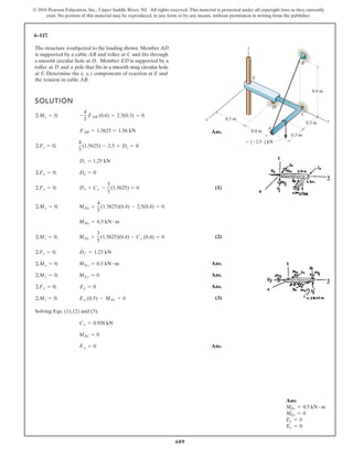
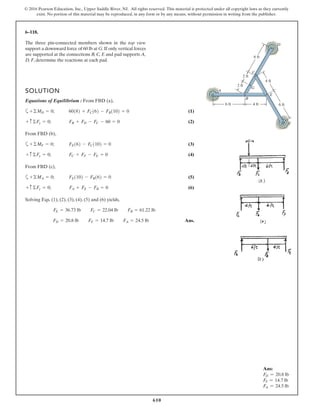
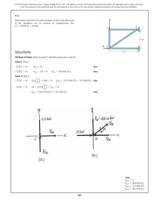
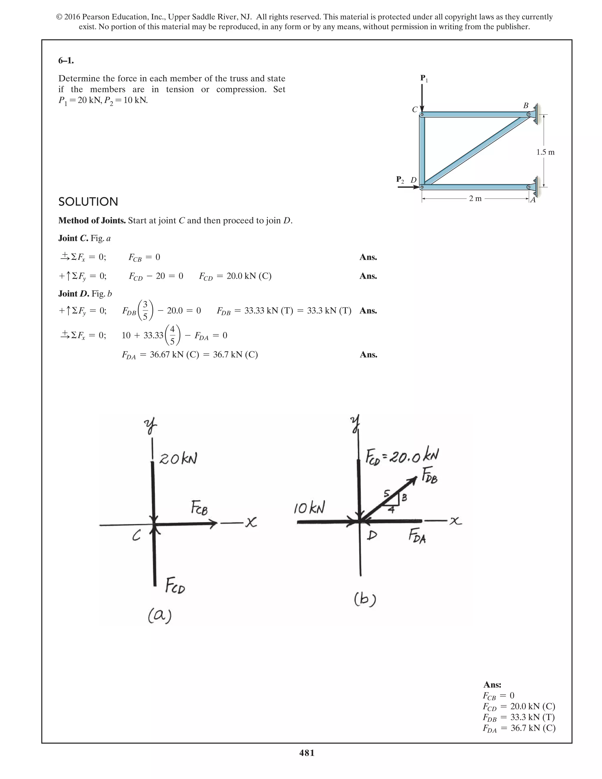
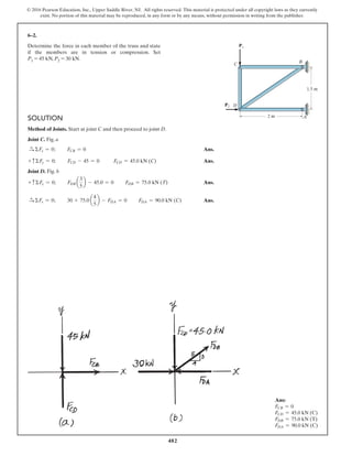
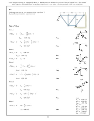
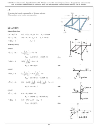
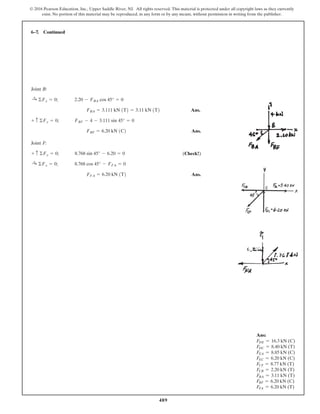
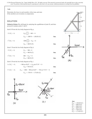
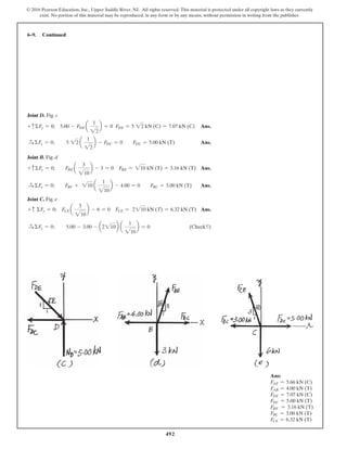
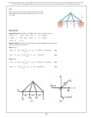
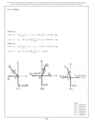
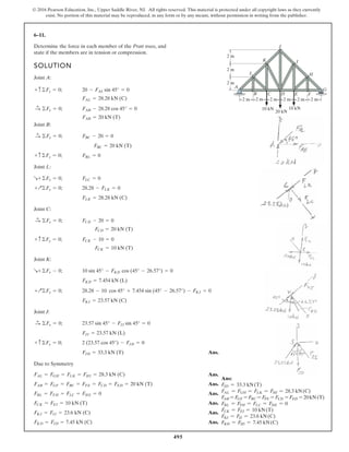
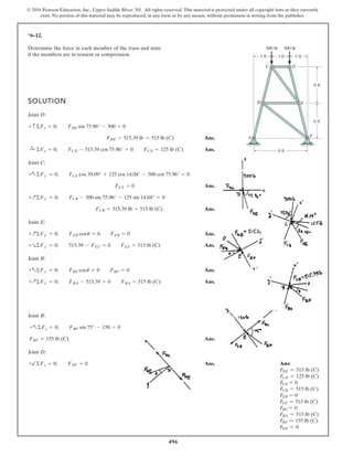
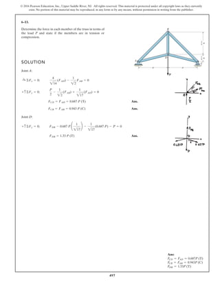
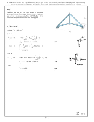
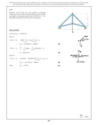
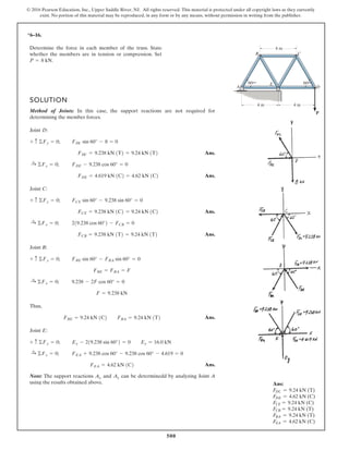
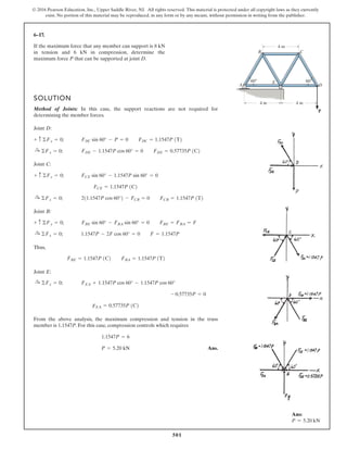
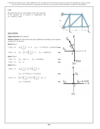
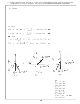
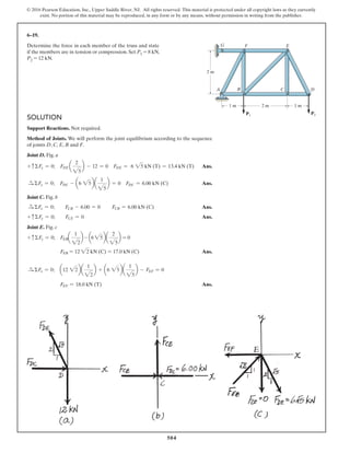
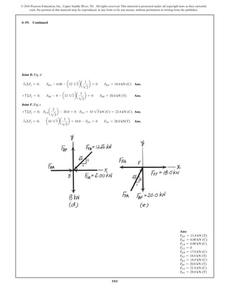
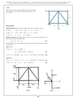
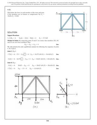
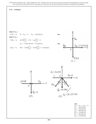
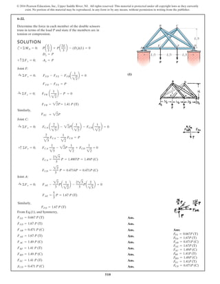
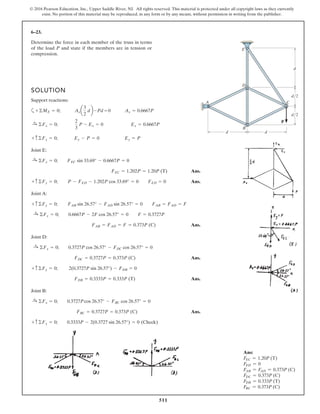
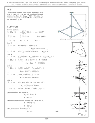
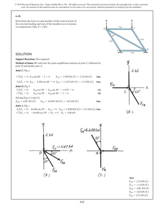
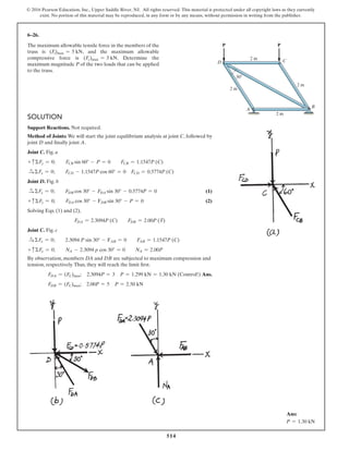
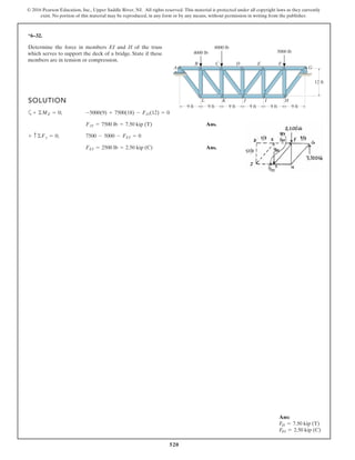
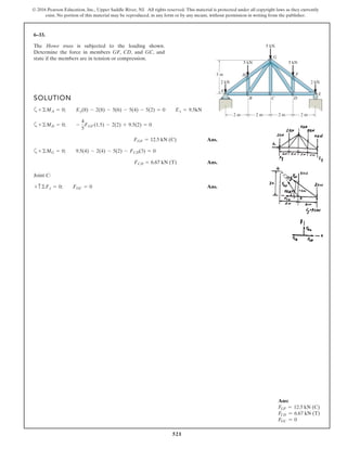
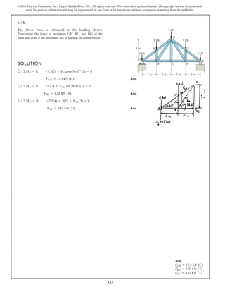
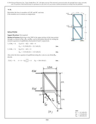
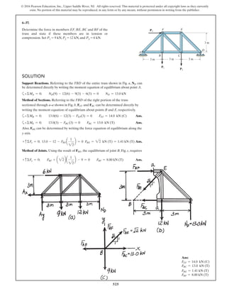
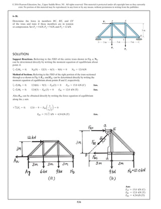
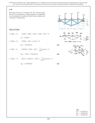
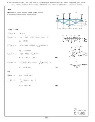
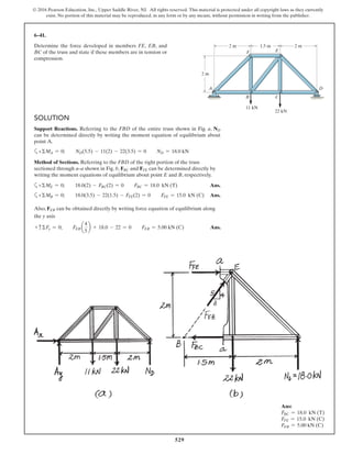
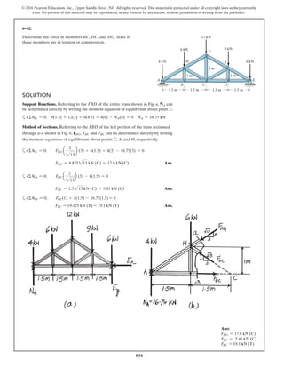
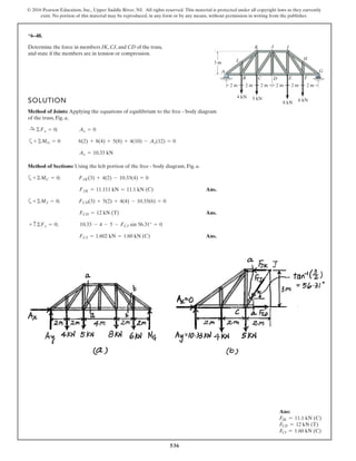
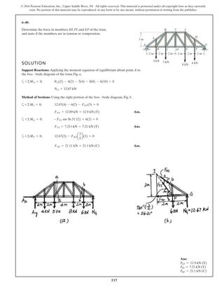
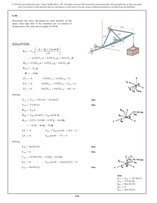
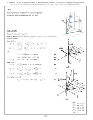
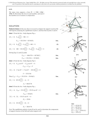
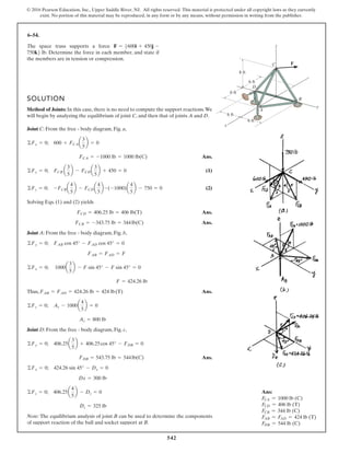
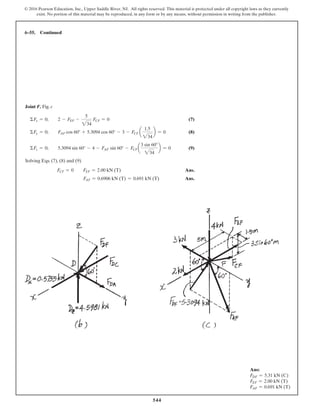
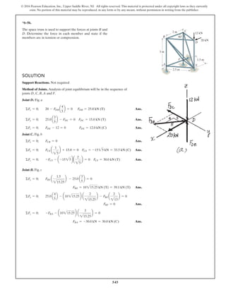
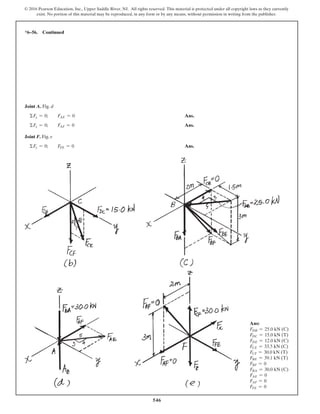
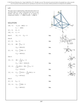
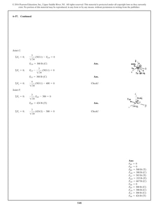
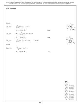
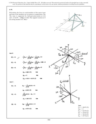
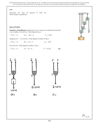
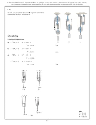
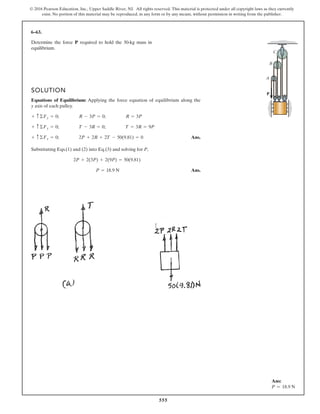
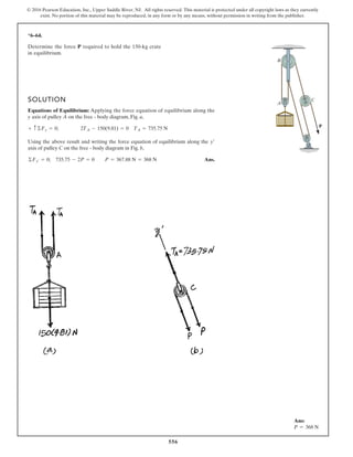
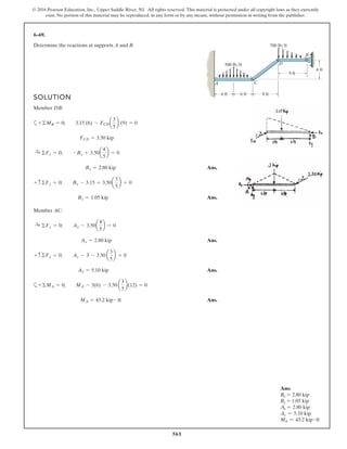
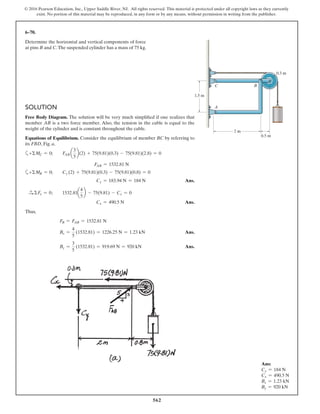
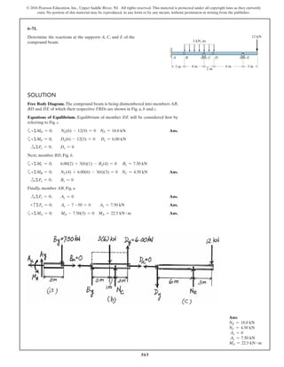
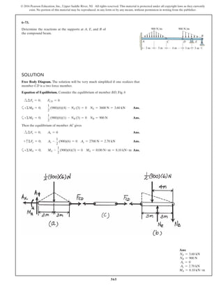
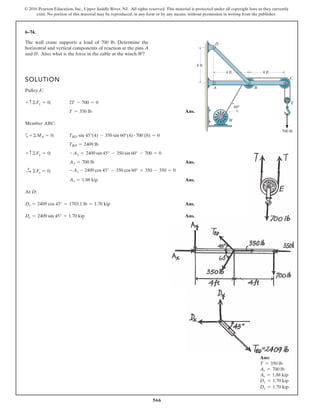
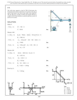
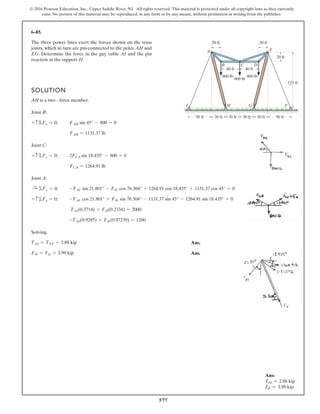
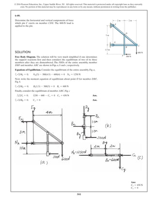
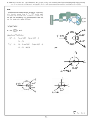
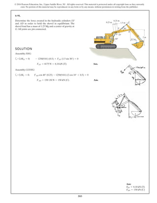
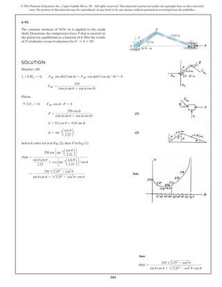
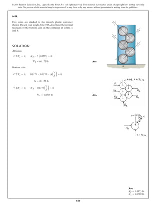
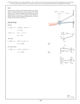
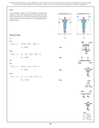
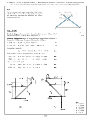
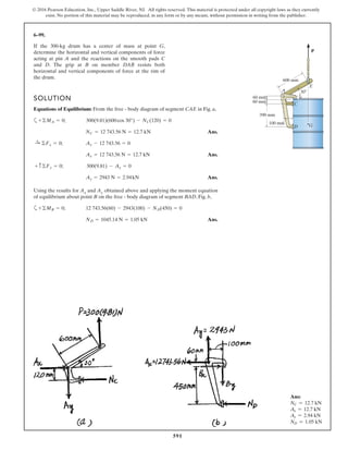
The document describes the process of analyzing a truss structure using the method of joints. It provides two examples of solving for the forces in each member of a truss given applied loads. In both examples, the document first calculates the support reactions, then analyzes the force in each member by examining the equilibrium of forces at each joint. It is able to determine the force magnitude and whether each member is in tension or compression.

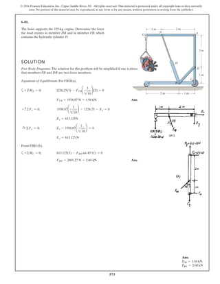
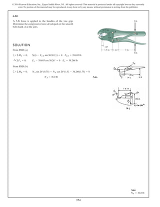
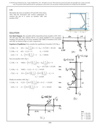
![604
© 2016 Pearson Education, Inc., Upper Saddle River, NJ. All rights reserved. This material is protected under all copyright laws as they currently
exist. No portion of this material may be reproduced, in any form or by any means, without permission in writing from the publisher.
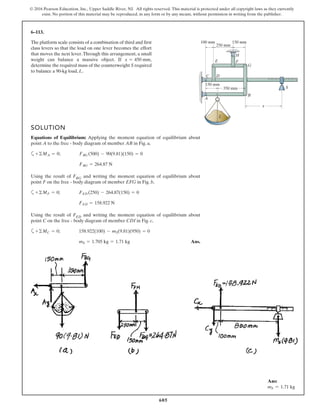
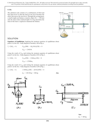
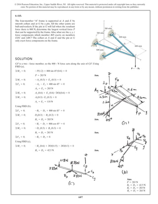
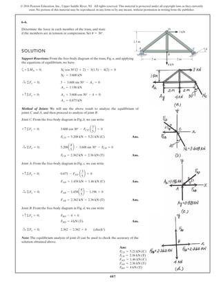
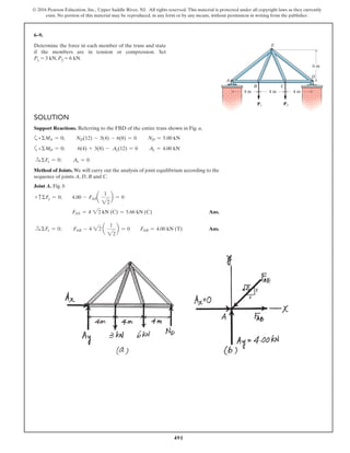
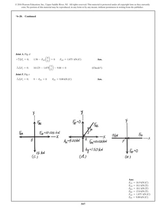
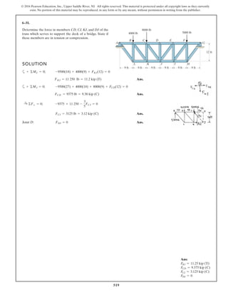
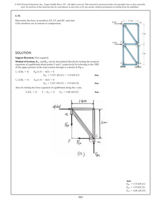
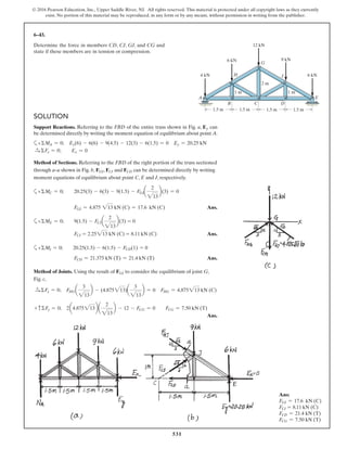
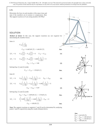
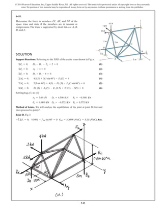
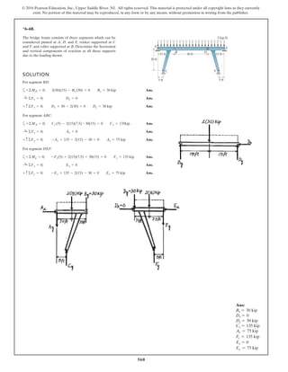
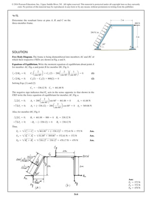
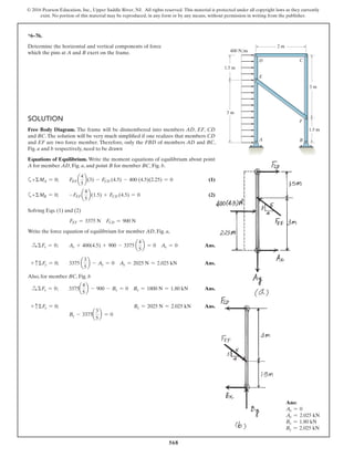
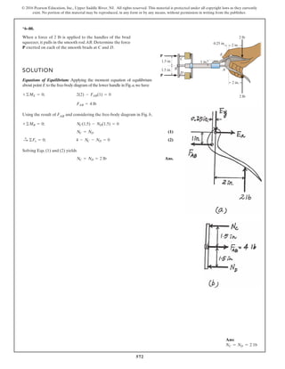
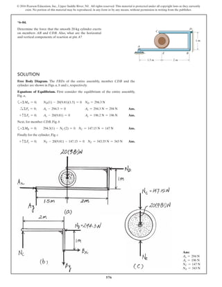
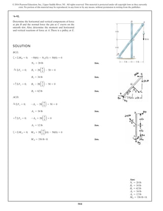
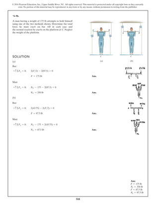
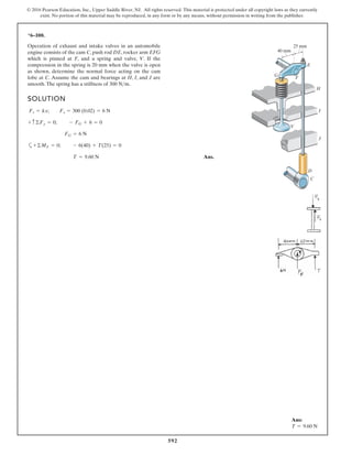
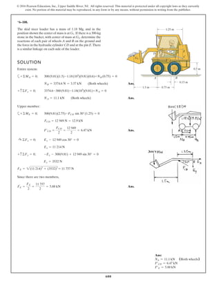
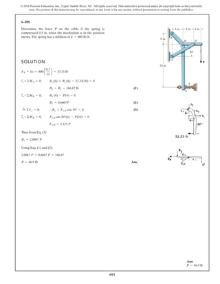
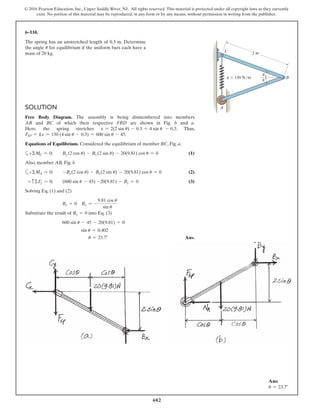
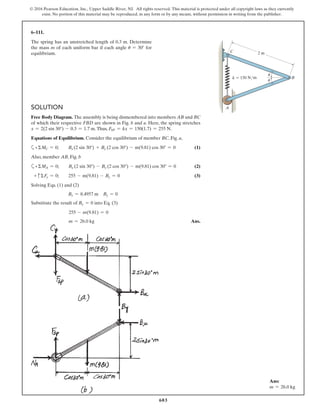
*6–112.
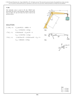
The piston C moves vertically between the two smooth
walls. If the spring has a stiffness of and is
unstretched when determine the couple M that
must be applied to AB to hold the mechanism in
equilibrium when u = 30°.
u = 0°,
k = 15 lb>in.,
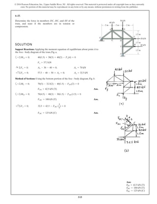
SOLUTION
Geometry:
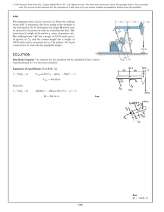
Free Body Diagram: The solution for this problem will be simplified if one
realizes that member CB is a two force member. Since the spring
. the spring force is
.
Equations of Equilibrium: Using the method of joints, [FBD (a)],
From FBD (b),
Ans.M = 170.08 lb # in = 14.2 lb # ft
a+©MA = 0; 27.97cos 40.53° (8) - M = 0
FCB = 27.97 lb
+ c©Fy = 0; FCB cos 19.47° - 26.37 = 0
Fsp = kx = 15 (1.758) = 26.37 lb
stretches x = lAC - l¿AC = 20 - 18.242 = 1.758 in
l¿AC
sin 130.53°
=
12
sin 30°
l¿AC = 18.242 in.
f = 180° - 30° - 19.47 = 130.53°
sin c
8
=
sin 30°
12
c = 19.47°
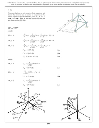
A
M
u
B
8 in.
12 in.
C
k = 15 lb/in.
Ans:
M = 14.2 lb # ft](https://image.slidesharecdn.com/chapter-6-structural-analysis-8th-edition-solution-191124212533/85/Chapter-6-structural-analysis-8th-edition-solution-124-320.jpg)