Downloaded 325 times
![Sign convention for bending moments:
The bending moment is considered as Sagging Bending
Moment if it tends to bend the beam to a curvature having
convexity at the bottom as shown in the Fig. given below.
Sagging Bending Moment is considered as positive bending
moment.
Fig. Sagging bending moment [Positive bending moment
]
Convexity](https://image.slidesharecdn.com/sfdbmd-180511185355/85/Sfd-bmd-6-320.jpg)
![Sign convention for bending moments:
Similarly the bending moment is considered as hogging
bending moment if it tends to bend the beam to a
curvature having convexity at the top as shown in the
Fig. given below. Hogging Bending Moment is
considered as Negative Bending Moment.
Fig. Hogging bending moment [Negative bending moment ]
Convexity](https://image.slidesharecdn.com/sfdbmd-180511185355/85/Sfd-bmd-7-320.jpg)
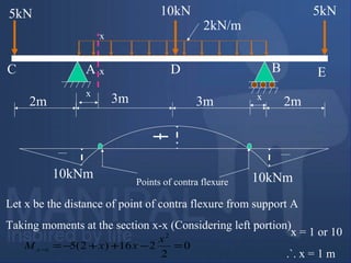
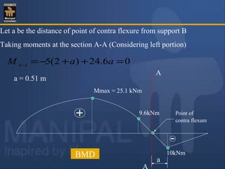
![Point of Contra flexure [Inflection point]:
It is the point on the bending moment diagram where
bending moment changes the sign from positive to
negative or vice versa.
It is also called ‘Inflection point’. At the point of
inflection point or contra flexure the bending moment
is zero.](https://image.slidesharecdn.com/sfdbmd-180511185355/85/Sfd-bmd-9-320.jpg)
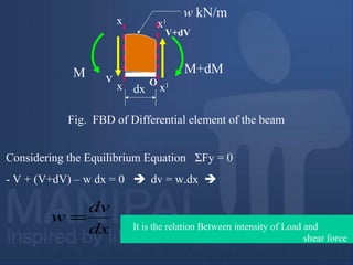
![dx
v
V+dV
M M+dM
Fig. FBD of Differential element of the beam
x
x x1
x1
w kN/m
O
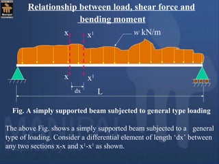
Taking moments about the point ‘O’ [Bottom-Right corner of the
differential element ]
- M + (M+dM) – V.dx – w.dx.dx/2 = 0
V.dx = dM
dx
dM
v =
It is the relation between shear force and BM
Neglecting the small quantity of higher order](https://image.slidesharecdn.com/sfdbmd-180511185355/85/Sfd-bmd-11-320.jpg)
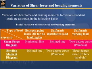
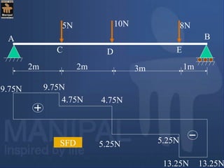
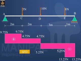
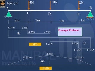
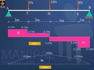
![Example Problem 1
E
5N 10N 8N
2m 2m 3m 1m
A
C D
B
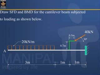
1. Draw shear force and bending moment diagrams [SFD
and BMD] for a simply supported beam subjected to
three point loads as shown in the Fig. given below.](https://image.slidesharecdn.com/sfdbmd-180511185355/85/Sfd-bmd-14-320.jpg)
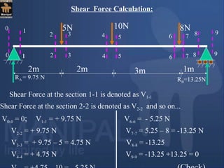
![E
5N 10N 8N
2m 2m 3m 1m
A
C D
B
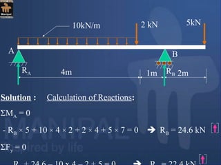
Solution:
Using the condition: ΣMA = 0
- RB × 8 + 8 × 7 + 10 × 4 + 5 × 2 = 0 RB = 13.25 N
Using the condition: ΣFy = 0
RA + 13.25 = 5 + 10 + 8 RA = 9.75 N
RA RB
[Clockwise moment is Positive]](https://image.slidesharecdn.com/sfdbmd-180511185355/85/Sfd-bmd-15-320.jpg)
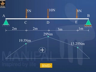
![Bending moment at A is denoted as MA
Bending moment at B is denoted as MB
and so on…
MA = 0 [ since it is simply supported]
MC = 9.75 × 2= 19.5 Nm
MD = 9.75 × 4 – 5 × 2 = 29 Nm
ME = 9.75 × 7 – 5 × 5 – 10 × 3 = 13.25 Nm
MB = 9.75 × 8 – 5 × 6 – 10 × 4 – 8 × 1 = 0
or M = 0 [ since it is simply supported]
Bending Moment Calculation](https://image.slidesharecdn.com/sfdbmd-180511185355/85/Sfd-bmd-19-320.jpg)
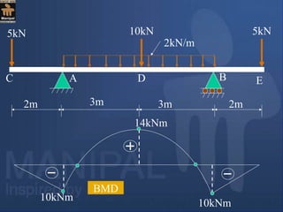
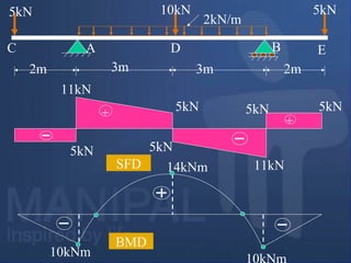
![2m 3m 3m 2m
5kN 10kN 5kN
2kN/m
A BC D E
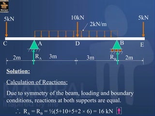
Bending Moment Calculation:
MC = ME = 0 [Because Bending moment at free end is zero]
MA = MB = - 5 × 2 = - 10 kNm
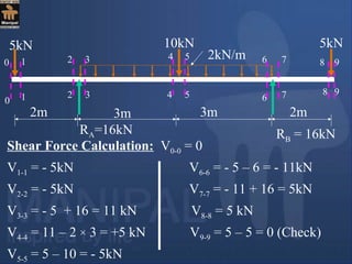
RA=16kN RB = 16kN](https://image.slidesharecdn.com/sfdbmd-180511185355/85/Sfd-bmd-27-320.jpg)
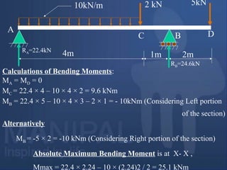
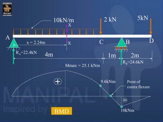
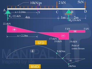
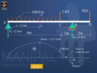
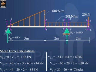
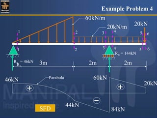
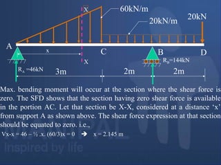
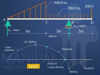
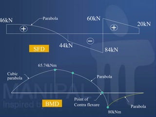
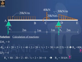
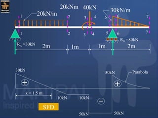
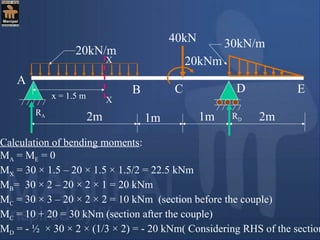
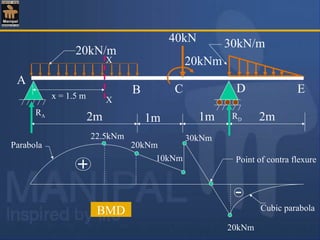
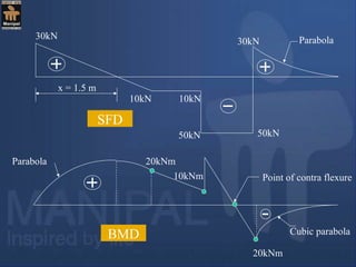
![Calculation of bending moments:
MA = MD = 0
MC = 46 × 3 – ½ × 3 × 60 × (1/3 × 3) = 48 kNm[Considering LHS of
section]
MB = -20 × 2 – 20 × 2 × 1 = - 80 kNm [Considering RHS of section]
Absolute Maximum Bending Moment, Mmax = 46 × 2.145 – ½ × 2.145
×(2.145 × 60/3) × (1/3 × 2.145) = 65.74 kNm
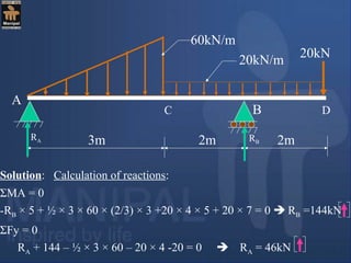
60kN/m
3m
20kN/m
20kN
2m 2m
A
B
RA =46kN
C D
RB=144kN](https://image.slidesharecdn.com/sfdbmd-180511185355/85/Sfd-bmd-46-320.jpg)
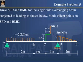
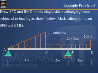
![Exercise Problems
Draw SFD and BMD for a single side overhanging beam
subjected to loading as shown below. Mark absolute
maximum bending moment on bending moment diagram and
locate point of contra flexure.
20kN/m
5kNm
15kN/m10kN
3m 1m 1m 2m1m 1m
[Ans: Absolute maximum BM = 60.625 kNm ]
VM-73](https://image.slidesharecdn.com/sfdbmd-180511185355/85/Sfd-bmd-65-320.jpg)
![10kN 16kN
1m
A B
2. Draw shear force and bending moment diagrams [SFD
and BMD] for a simply supported beam subjected to
loading as shown in the Fig. given below. Also locate
and determine absolute maximum bending moment.
4kN/m
1m 1m 1m2m
600
[Ans: Absolute maximum bending moment = 22.034kNm
Its position is 3.15m from Left hand support ]
Exercise Problems VM-74](https://image.slidesharecdn.com/sfdbmd-180511185355/85/Sfd-bmd-66-320.jpg)
![50kN
A
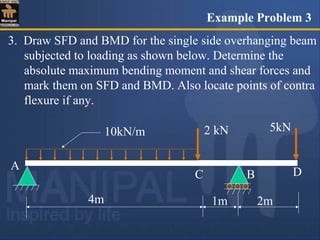
3. Draw shear force and bending moment diagrams [SFD
and BMD] for a single side overhanging beam subjected
to loading as shown in the Fig. given below. Locate
points of contra flexure if any.
10kN/m
1m 1m 3m
[Ans : Position of point of contra flexure from RHS = 0.375m]
Exercise Problems
25kN/m
10kNm
B
2m
VM-75](https://image.slidesharecdn.com/sfdbmd-180511185355/85/Sfd-bmd-67-320.jpg)
![8kN
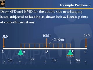
4. Draw SFD and BMD for a double side overhanging beam
subjected to loading as shown in the Fig. given below.
Locate the point in the AB portion where the bending
moment is zero.
4kN/m
[Ans : Bending moment is zero at mid span]
Exercise Problems
B
2m
8kN
16kN
2m 2m 2m
A
VM-76](https://image.slidesharecdn.com/sfdbmd-180511185355/85/Sfd-bmd-68-320.jpg)
![5. A single side overhanging beam is subjected to uniformly distributed
load of 4 kN/m over AB portion of the beam in addition to its self
weight 2 kN/m acting as shown in the Fig. given below. Draw SFD
and BMD for the beam. Locate the inflection points if any. Also locate
and determine maximum negative and positive bending moments.
4kN/m
[Ans :Max. positive bending moment is located at 2.89 m from LHS.
and whose value is 37.57 kNm ]
Exercise Problems
B
2m6m
A
2kN/m
VM-77](https://image.slidesharecdn.com/sfdbmd-180511185355/85/Sfd-bmd-69-320.jpg)
![5kN
6. Three point loads and one uniformly distributed load are
acting on a cantilever beam as shown in the Fig. given
below. Draw SFD and BMD for the beam. Locate and
determine maximum shear force and bending moments.
2kN/m
[Ans : Both Shear force and Bending moments are maximum
at supports.]
Exercise Problems
B
20kN10kN
A
1m 1m 1m
VM-78](https://image.slidesharecdn.com/sfdbmd-180511185355/85/Sfd-bmd-70-320.jpg)
![200N 100N
A B
7. One side overhanging beam is subjected loading as
shown below. Draw shear force and bending moment
diagrams [SFD and BMD] for beam. Also determine
maximum hogging bending moment.
30N/m
4m
[Ans: Max. Hogging bending moment = 735 kNm]
Exercise Problems
4m3m
VM-79](https://image.slidesharecdn.com/sfdbmd-180511185355/85/Sfd-bmd-71-320.jpg)
![5kN
8. A cantilever beam of span 6m is subjected to three point
loads at 1/3rd
points as shown in the Fig. given below.
Draw SFD and BMD for the beam. Locate and determine
maximum shear force and hogging bending moment.
[Ans : Max. Shear force = 20.5kN, Max BM= 71kNm
Both max. shear force and bending moments will occur
at supports.]
Exercise Problems
B
10kN
A 2m 2m 2m
300
0.5m 8kN 5kN
VM-80](https://image.slidesharecdn.com/sfdbmd-180511185355/85/Sfd-bmd-72-320.jpg)
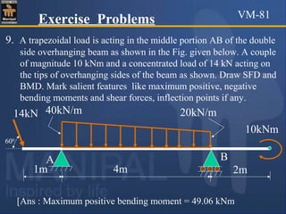
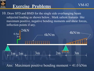

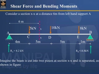
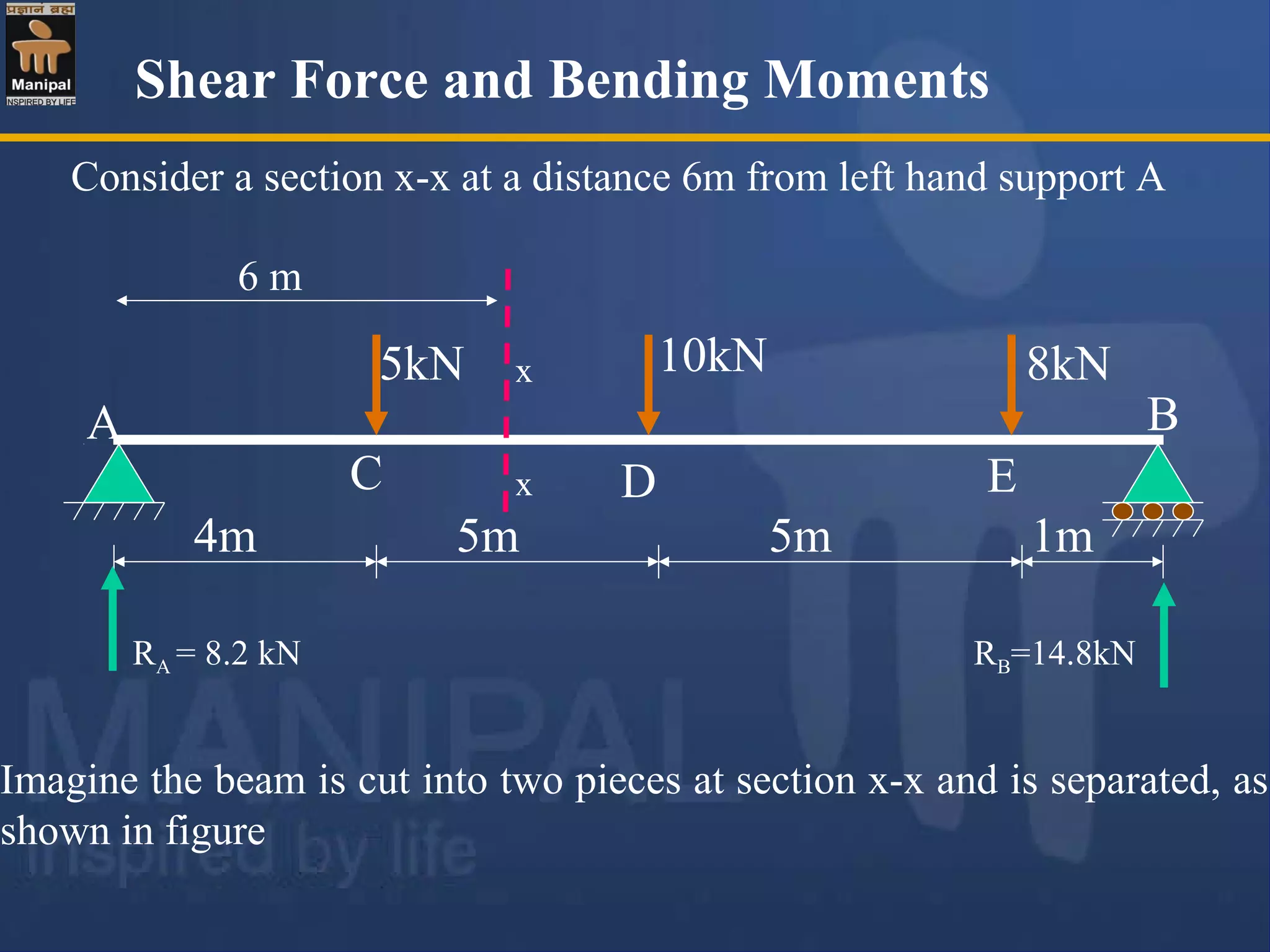
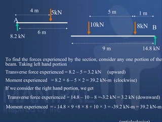
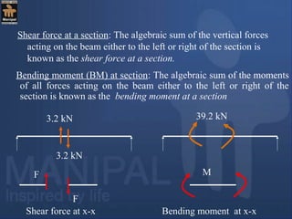
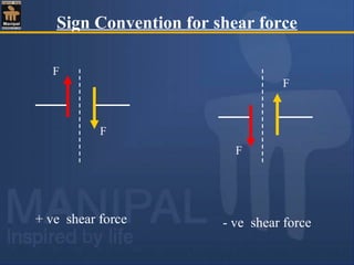
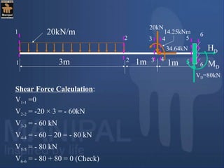
The document discusses shear force and bending moments in beams. It provides examples of calculating the shear force and bending moment at a section for different loading conditions. Shear force is the sum of vertical forces to the left or right of a section, while bending moment is the sum of moments from forces left or right of the section. Shear force tries to shear a section, while bending moment bends it. Positive and negative signs are used to indicate the type of bending based on curvature.


