Downloaded 835 times
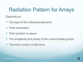
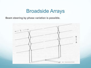
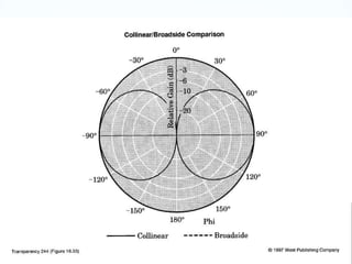
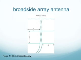
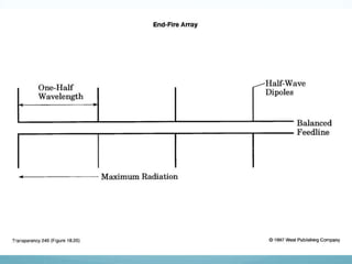
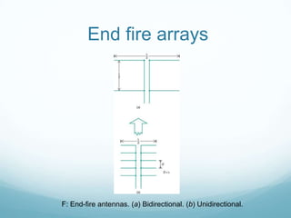
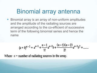


The document discusses different types of antenna arrays, including broadside arrays, end-fire arrays, and binomial arrays. A broadside array consists of half-wave dipoles spaced by half wavelengths that produces a highly directional radiation pattern perpendicular to the array. An end-fire array uses two half-wave dipoles spaced by half a wavelength and radiates in the plane of the dipoles. A binomial array arranges radiating sources according to binomial coefficients to reduce side lobes and optimize directivity.


