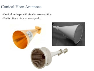
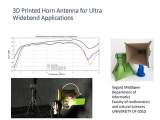
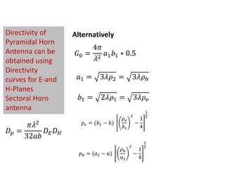
By completing this presentation will be have a clear idea about Antenna's working principles, Antenna's Types & Antenna's Parameters. At the end to this document you'll have a brief idea about Antenna's Tilt vs Distance Calculation & Cluster wise optimum Antenna Selection procedure. Impact of antenna PIM & VSWR have been described elaborately in this document as well.
Its a good presentation on Antenna topic because every one is know that in electrical engineering antenna is a complete subject & its too much difficult subject of electrical engineering....I hope this ppt slides helpful in your future...Thanks A lot guys.......
KINDLY REGARDS
KHAWAJA SHAHBAZ IQBAL
ELECTRICAL ENGINEER
UNIVERSITY OF CENTRAL PUNJAB ,LAHORE ,PAKISTAN
+923360690272
A horn antenna or microwave horn is an antenna that consists of a flaring metal waveguide shaped like a horn to direct radio waves in a beam. Horns are widely used as antennas at UHF and microwave frequencies, above 300 MHz.
Broadside Array vs end-fire array
Higher directivity.
Provide increased directivity in
elevation and azimuth planes.
Generally used for reception.
Impedance match difficulty in
high power transmissions.
Variants are:
Horizontal Array of Dipoles
RCA Fishborne Antenna
Series Phase Array
In radio and electronics, an antenna (plural antennae or antennas), or aerial, is an electrical device which converts electric power into radio waves, and vice versa.[1] It is usually used with a radio transmitter or radio receiver. In transmission, a radio transmitter supplies an electric current oscillating at radio frequency (i.e. a high frequency alternating current (AC)) to the antenna's terminals, and the antenna radiates the energy from the current as electromagnetic waves (radio waves). In reception, an antenna intercepts some of the power of an electromagnetic wave in order to produce a tiny voltage at its terminals, that is applied to a receiver to be amplified.
A dipole antenna is the simplest antenna but its radiation characteristics are very good. The main drawback of a dipole antenna is very narrow bandwidth. The analysis of a dipole antenna can be performed with integration of Hertzian dipoles.
Frequency-independent (FI) antennas are radiating structures capable of maintaining consistent impedance and pattern characteristics over multiple-decade bandwidths. Their finite size limits the lowest frequency of operation, and the finite precision of the center region bounds the highest frequency of operation.
hello readers i give my PPT presentation for about antenna and ther properties and working explain in this ppt
i hope you like it THANK YOU.......!!!!!!!
The aperture is defined as the area, oriented perpendicular to the direction of an incoming radio wave, which would intercept the same amount of power from that wave as is produced by the antenna receiving it. A horn antenna or microwave horn is an antenna that consists of a flaring metal waveguide shaped like a horn to direct radio waves in a beam. Horns are widely used as antennas at UHF and microwave frequencies, above 300 MHz.
Industrial Training at Shahjalal Fertilizer Company Limited (SFCL)MdTanvirMahtab2
This presentation is about the working procedure of Shahjalal Fertilizer Company Limited (SFCL). A Govt. owned Company of Bangladesh Chemical Industries Corporation under Ministry of Industries.
Hybrid optimization of pumped hydro system and solar- Engr. Abdul-Azeez.pdffxintegritypublishin
Advancements in technology unveil a myriad of electrical and electronic breakthroughs geared towards efficiently harnessing limited resources to meet human energy demands. The optimization of hybrid solar PV panels and pumped hydro energy supply systems plays a pivotal role in utilizing natural resources effectively. This initiative not only benefits humanity but also fosters environmental sustainability. The study investigated the design optimization of these hybrid systems, focusing on understanding solar radiation patterns, identifying geographical influences on solar radiation, formulating a mathematical model for system optimization, and determining the optimal configuration of PV panels and pumped hydro storage. Through a comparative analysis approach and eight weeks of data collection, the study addressed key research questions related to solar radiation patterns and optimal system design. The findings highlighted regions with heightened solar radiation levels, showcasing substantial potential for power generation and emphasizing the system's efficiency. Optimizing system design significantly boosted power generation, promoted renewable energy utilization, and enhanced energy storage capacity. The study underscored the benefits of optimizing hybrid solar PV panels and pumped hydro energy supply systems for sustainable energy usage. Optimizing the design of solar PV panels and pumped hydro energy supply systems as examined across diverse climatic conditions in a developing country, not only enhances power generation but also improves the integration of renewable energy sources and boosts energy storage capacities, particularly beneficial for less economically prosperous regions. Additionally, the study provides valuable insights for advancing energy research in economically viable areas. Recommendations included conducting site-specific assessments, utilizing advanced modeling tools, implementing regular maintenance protocols, and enhancing communication among system components.
Saudi Arabia stands as a titan in the global energy landscape, renowned for its abundant oil and gas resources. It's the largest exporter of petroleum and holds some of the world's most significant reserves. Let's delve into the top 10 oil and gas projects shaping Saudi Arabia's energy future in 2024.
NUMERICAL SIMULATIONS OF HEAT AND MASS TRANSFER IN CONDENSING HEAT EXCHANGERS...ssuser7dcef0
Power plants release a large amount of water vapor into the
atmosphere through the stack. The flue gas can be a potential
source for obtaining much needed cooling water for a power
plant. If a power plant could recover and reuse a portion of this
moisture, it could reduce its total cooling water intake
requirement. One of the most practical way to recover water
from flue gas is to use a condensing heat exchanger. The power
plant could also recover latent heat due to condensation as well
as sensible heat due to lowering the flue gas exit temperature.
Additionally, harmful acids released from the stack can be
reduced in a condensing heat exchanger by acid condensation. reduced in a condensing heat exchanger by acid condensation.
Condensation of vapors in flue gas is a complicated
phenomenon since heat and mass transfer of water vapor and
various acids simultaneously occur in the presence of noncondensable
gases such as nitrogen and oxygen. Design of a
condenser depends on the knowledge and understanding of the
heat and mass transfer processes. A computer program for
numerical simulations of water (H2O) and sulfuric acid (H2SO4)
condensation in a flue gas condensing heat exchanger was
developed using MATLAB. Governing equations based on
mass and energy balances for the system were derived to
predict variables such as flue gas exit temperature, cooling
water outlet temperature, mole fraction and condensation rates
of water and sulfuric acid vapors. The equations were solved
using an iterative solution technique with calculations of heat
and mass transfer coefficients and physical properties.
Immunizing Image Classifiers Against Localized Adversary Attacksgerogepatton
This paper addresses the vulnerability of deep learning models, particularly convolutional neural networks
(CNN)s, to adversarial attacks and presents a proactive training technique designed to counter them. We
introduce a novel volumization algorithm, which transforms 2D images into 3D volumetric representations.
When combined with 3D convolution and deep curriculum learning optimization (CLO), itsignificantly improves
the immunity of models against localized universal attacks by up to 40%. We evaluate our proposed approach
using contemporary CNN architectures and the modified Canadian Institute for Advanced Research (CIFAR-10
and CIFAR-100) and ImageNet Large Scale Visual Recognition Challenge (ILSVRC12) datasets, showcasing
accuracy improvements over previous techniques. The results indicate that the combination of the volumetric
input and curriculum learning holds significant promise for mitigating adversarial attacks without necessitating
adversary training.
Using recycled concrete aggregates (RCA) for pavements is crucial to achieving sustainability. Implementing RCA for new pavement can minimize carbon footprint, conserve natural resources, reduce harmful emissions, and lower life cycle costs. Compared to natural aggregate (NA), RCA pavement has fewer comprehensive studies and sustainability assessments.
Forklift Classes Overview by Intella PartsIntella Parts
Discover the different forklift classes and their specific applications. Learn how to choose the right forklift for your needs to ensure safety, efficiency, and compliance in your operations.
For more technical information, visit our website https://intellaparts.com
Cosmetic shop management system project report.pdfKamal Acharya
Buying new cosmetic products is difficult. It can even be scary for those who have sensitive skin and are prone to skin trouble. The information needed to alleviate this problem is on the back of each product, but it's thought to interpret those ingredient lists unless you have a background in chemistry.
Instead of buying and hoping for the best, we can use data science to help us predict which products may be good fits for us. It includes various function programs to do the above mentioned tasks.
Data file handling has been effectively used in the program.
The automated cosmetic shop management system should deal with the automation of general workflow and administration process of the shop. The main processes of the system focus on customer's request where the system is able to search the most appropriate products and deliver it to the customers. It should help the employees to quickly identify the list of cosmetic product that have reached the minimum quantity and also keep a track of expired date for each cosmetic product. It should help the employees to find the rack number in which the product is placed.It is also Faster and more efficient way.
3. Horn Antenna
• Horn antennas often have a directional radiation
pattern with a high antenna gain, which can
range up to 25 dB in some cases, with 10-20 dB
being typical.
• The bandwidth for practical horn antennas can
be on the order of 20:1 (for instance, operating
from 1 GHz-20 GHz), with a 10:1 bandwidth not
being uncommon
• Horn antennas have very little loss, so the
directivity of a horn is roughly equal to its gain
4. 3D Printed Horn Antenna for Ultra
Wideband Applications
Vegard Midtbøen
Department of
Informatics
Faculty of mathematics
and natural sciences
UNIVERSITY OF OSLO
5. Rectangular Waveguide
• Impedance of free space: 377
Ohm
• Generally: impedance of
waveguide: 50 Ohm
• No matching
• The flaring causes it to match
with the free space
• Thus horn antenna
a
6. Rectangular Waveguide
• Impedance of free space: 377
Ohm
• Generally: impedance of
waveguide: 50 Ohm
• No matching
• The flaring causes it to match
with the free space
• Thus horn antenna
a
8. Pyramidal Horn Antenna
• has flaring on both sides.
• If flaring is done on both the E & H walls of a rectangular waveguide,
then pyramidal horn antenna is produced.
• this antenna has the shape of a truncated pyramid.
• probably the most popular antenna in the microwave frequency
ranges (from ≈1 GHz up to ≈18 GHz)
9. Radiation Pattern
This antenna is simulated
using a commercial solver,
FEKO (which runs method of
moments). The radiation
pattern at 2 GHz is shown
right side
a=3.69 inches, b=1.64 inches
A=30 inches, and B=23.8
inches
15. X-Band (8.2-12.4 GHz), f=11 GHz Horn
Gain=22.6 dB
a=2.286 cm
b=1.016 cm
Find: Dimensions of Pyramidal Horn
0100 log106.22)( GdBG 97.18110 26.2
0 G
7273.2
1011
1030
9
9
x
x
3725.0
7273.2
016.1
b 8382.0
7273.2
286.2
a
cm
NUMERICAL
At
f=11
GHz
16. Initial value of χ
5539.11
22
97.181
22
0
1
G
316.301157.11 e
753.320094.12
1
8
2
3
0
G
h
2𝜒 −
𝑏
𝜆
2
2𝜒 − 1 =
𝐺0
2𝜋
3
2𝜋
1
𝜒
−
𝑎
𝜆
2
𝐺0
2
6𝜋3
1
𝜒
− 1Put this value in eqn
After few more tries χ=11.1157
cm
cm
NUMERICAL
17. 370.16002.6
2
3
2
33 0
21
G
a h
859.12715.4222 11 eb
286.27005.10
4
1
)(
2
1
2
1
21
b
bbp e
e
286.27005.10
4
1
)(
2
1
2
1
21
a
aap h
h
cm
cm
NUMERICAL
cm
cm
18. Final Design
X-Band (8.2-12.4 GHz), f=11 GHz Horn
Gain=22.6 dB
286.27 he pp
85.12
370.16
1
1
b
a cm
cm
a=2.286 cm
b=1.016
waveguide
SIZE OF HORN
NUMERICAL
19. With a blink
of an eye
If you have
this graph
For Gain:
22.6 dBi
20. PHYSICAL SPECIFICATIONS
Width 36.4 mm (1.43 in)
Depth 58.8 mm (2.32 in)
Height 25.9 mm (1.02 in)
Weight 125 g (0.28 lb)
Material gold–plated brass
ELECTRICAL SPECIFICATIONS
Polarization linear
Frequency Range (33) 38 – 50 GHz
VSWR max. < 1.3:1
Impedance 50 Ω
Connector 2.4mmfemale
Gain 19 - 21 dB
http://www.rfspin.cz/en/antennas
/pyramidal-horn-antennas/ha50
21. G= 10 ln
4𝜋𝑎𝑏
𝜆2 + 𝜂 𝑒 + 𝜂ℎ [𝑑𝐵]
𝜂 𝑒, 𝜂ℎ = 𝑎𝑝𝑒𝑟𝑡𝑢𝑟𝑒 𝑒𝑓𝑓𝑖𝑐𝑖𝑒𝑛𝑐𝑦
le
lh
a
b
23. Conical Horn Antennas
• Conical in shape with circular cross-section
• Fed is often a circular waveguide.
24. Geometry of Conical horn
𝑫 𝒄 𝒅𝑩 = 10 𝐥𝐨𝐠10 𝝐 𝒂𝒑
4𝝅
𝝀2
𝝅𝒂2
= 10 𝐥𝐨𝐠10
𝑪
𝝀
2
− 𝑳(𝒔)
𝑳 𝒔 = −𝟏𝟎𝐥𝐨𝐠 𝟏𝟎(𝝐 𝒂𝒑)
Directivity of Uniform Circular Aperture
Loss due to the Aperture Efficiency;
Directivity of the conical horn
antenna is given by,
Aperture Efficiency(𝝐 𝒂𝒑) is usually 51%
for Conical Horn Antennas.
∗ 𝝍 𝒄=Flaring Angle
L= Axial Length
25. Design of Conical horn
For optimum directivity,
𝒅 𝒎 ≃ 𝟑𝒍𝝀
𝒔 =
𝒅 𝒎
2
8𝒍𝝀
;
𝑳 𝒔 = (𝟎. 𝟖 − 𝟏. 𝟕𝟏𝒔 + 𝟐𝟔. 𝟐𝟓𝒔 𝟐 − 𝟏𝟕. 𝟕𝟗𝒔 𝟑
Loss figure(dB) is computed as,
where,
Maximum Phase Deviation(in no. of 𝒘𝒂𝒗𝒆𝒍𝒆𝒏𝒈𝒕𝒉𝒔)
26. • For a given length, as the
flare angle increases, the
directivity increases until
it reaches a maximum
value after which it starts
to decrease again.
• The decrease in the
directivity is due to the
phase deviations across
the aperture which leads
to cancellation in the far
field.
Directivity,𝑫𝒄(dB)
Diameter of horn aperture, 𝒅 𝒎(Wavelengths)
Figure : Directivity of a conical horn as a function
of aperture diameter and for different axial horn
lengths
27. Figure : Dimensions of conical horn(in wavelengths)
Vs directivity(or gain, if no loss)
• Noting the dashed
lines, gain of 20 dBi
requires horn
antenna 𝑳 𝝀=6.0 and
diameter𝑫 𝝀 = 𝟒. 𝟑.
• These dimensions
are close to
optimum.
28. Radiation Pattern of Conical Horn
Antenna should be designed in such a way that the
wave’s direction from antenna is perpendicular to
horn aperture.
29. Corrugated Horns
• Provides reduced edge diffraction, improved pattern
symmetry and reduced cross-polarization(less E field in H
plane).
Figure: Cross section of circular waveguide-fed corrugated
horn with a corrugated transition
Figure: Corrugations of
width w and depth d
30. Corrugated Horns
• Efficiencies of the order of 75–80% can be
obtained with improved feed systems utilizing
corrugated horns.
• Corrugations with depth λ/2 acts as a conducting
surface while that with λ/4 depth in horn antenna
present a high impedance.
32. Sectoral Horn Antenna
• A pyramidal horn with only one pair of sides flared and the other pair
parallel.
• It produces a fan-shaped beam, which is narrow in the plane of the
flared sides, but wide in the plane of the narrow sides.
• These types are often used as feed horns for wide search radar
antennas.
33. Types of Sectoral Horn Antenna
• E-plane horn antenna : This form of antenna is one that is flared in
the direction of the electric or E-field in the waveguide.
• H-plane horn antenna : This form of antenna is one that is flared in
the direction of the electric or H-field in the waveguide.
34. Advantages of Horn Antenna
• They can operate over wide ranges of frequencies.
• Very wide bandwidth, for example allowing it to operate from 1GHz
to 20GHz, 20:1.
• High Directivity.
• High gain.
• Support for wide applications.
35. Applications
• They are used as feeders (called feed horn) for larger antenna
structures such as parabolic antennas, as directive antennas for such
devices as radar guns, automatic doors openers, microwave
radiometer.
• A common element of phase array.
• Satellite and microwave communications.
• Used in the calibration, other high gain antenna.
• Used for making electromagnetic interference measurement.
36. References
• Antenna-theory.com
• Antennas and Wave Propagation, John D Kraus
• Satellite Communication, Lecture Slide, Ippei Kashiwagi
• www.rfspin.cz
• 3D Printed Horn Antenna for Ultra Wideband Applications, Vegard
Midtbøen
• Horn Antennas, Prof. Girish Kumar