Downloaded 351 times
![WHY BICONNICAL ANTENNA ?
• Since 2002, the Federal Communication Commission (FCC)
regulated the frequency band from 3.1-10.6 GHz for low-
powered ultra-wideband (UWB) wireless communication [1].
• UWB's combination of larger spectrum, lower power and
pulsed data improves speed and reduces interference with
other wireless spectra.
• Based on the Regulation for UWB communications, one of the
most crucial components is the antenna.
• Biconical antenna configuration is one of many configurations
[2]-[4] that can be used to achieve broadband characteristics.](https://image.slidesharecdn.com/biconicalantenna-140810223804-phpapp01/75/Design-and-Application-of-Biconical-Antenna-2-2048.jpg)
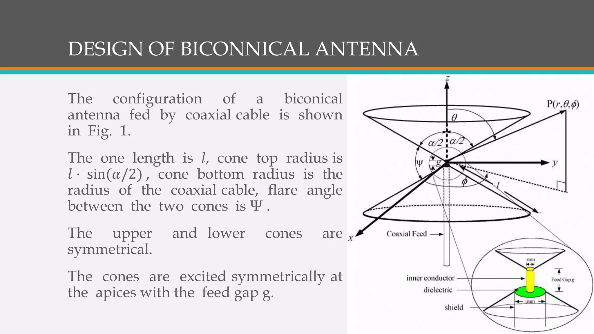
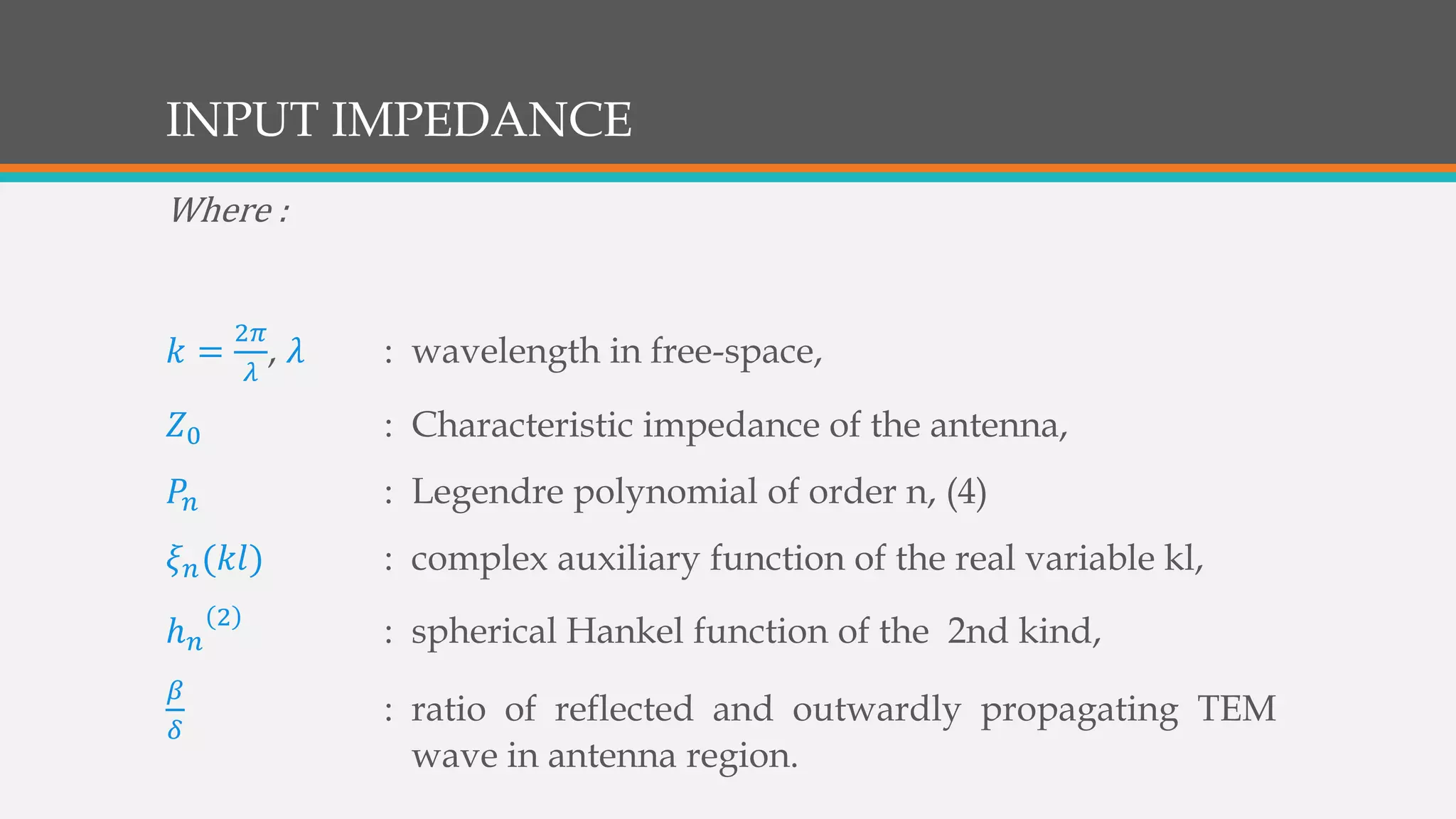
![INPUT IMPEDANCE
The input impedance of the antenna with conical length / and
cone angle as given by Papas and King [5] is
𝑍𝑖𝑛 = 𝑍0
1−𝛽/𝛿
1+𝛽/𝛿
where 𝑍0 = 60𝑙𝑛 × 𝑐𝑜𝑡
∝
4
𝛽
𝛿
= 𝑒−2𝑗𝑘𝑙
1 + 𝑗
60
𝑍0
𝑛=1
∞ 2𝑛 + 1
𝑛 𝑛 + 1
𝑃𝑛 cos
∝
2
2
𝜉 𝑛(𝑘𝑙)
−1 + 𝑗
60
𝑍0
𝑛=1
∞ 2𝑛 + 1
𝑛 𝑛 + 1
𝑃𝑛 cos
∝
2
2
𝜉 𝑛(𝑘𝑙)
And 𝜉 𝑛 𝑘𝑙 =
ℎ 𝑛
2
(𝑘𝑙)
ℎ 𝑛−1
2
𝑘𝑙 −
𝑛
𝑘𝑙
ℎ 𝑛
2
(𝑘𝑙)](https://image.slidesharecdn.com/biconicalantenna-140810223804-phpapp01/75/Design-and-Application-of-Biconical-Antenna-4-2048.jpg)
![RADIATION PATTERN
𝑅 𝜃 =
𝐸 𝜃(𝑟, 𝜃)
𝐸 𝜃(𝑟, 90 𝜊)
=
𝑛=1
∞
𝑃
𝑛 cos
𝛼
2 𝑃 𝑛
1(cos 𝜃)
ℎ 𝑛−1
2
(𝑘𝑙−
𝑛
𝑘𝑙
)ℎ 𝑛
2
(𝑘𝑙)
2𝑛+1
𝑛(𝑛+1)
𝑗2
𝑛=1
∞
𝑃
𝑛 cos
𝛼
2 𝑃 𝑛
1(0)
ℎ 𝑛−1
2
(𝑘𝑙−
𝑛
𝑘𝑙
)ℎ 𝑛
2
(𝑘𝑙)
2𝑛+1
𝑛(𝑛+1)
𝑗2
where 𝑃𝑛
1cos(𝜃) =
−𝑑𝑃 𝑛(𝑐𝑜𝑠 𝜃)
𝑑𝜃
and the
summation is over odd integral.
The antenna was
considered to be an
isolated source in free-
space with azimuthally
independent radiation
in the H-plane. The E-
plane far-field radiation
pattern normalized to
the field at broadside
(𝜃 = 90 𝜊) has been
analyzed by Papas and
King [6], is](https://image.slidesharecdn.com/biconicalantenna-140810223804-phpapp01/75/Design-and-Application-of-Biconical-Antenna-6-2048.jpg)
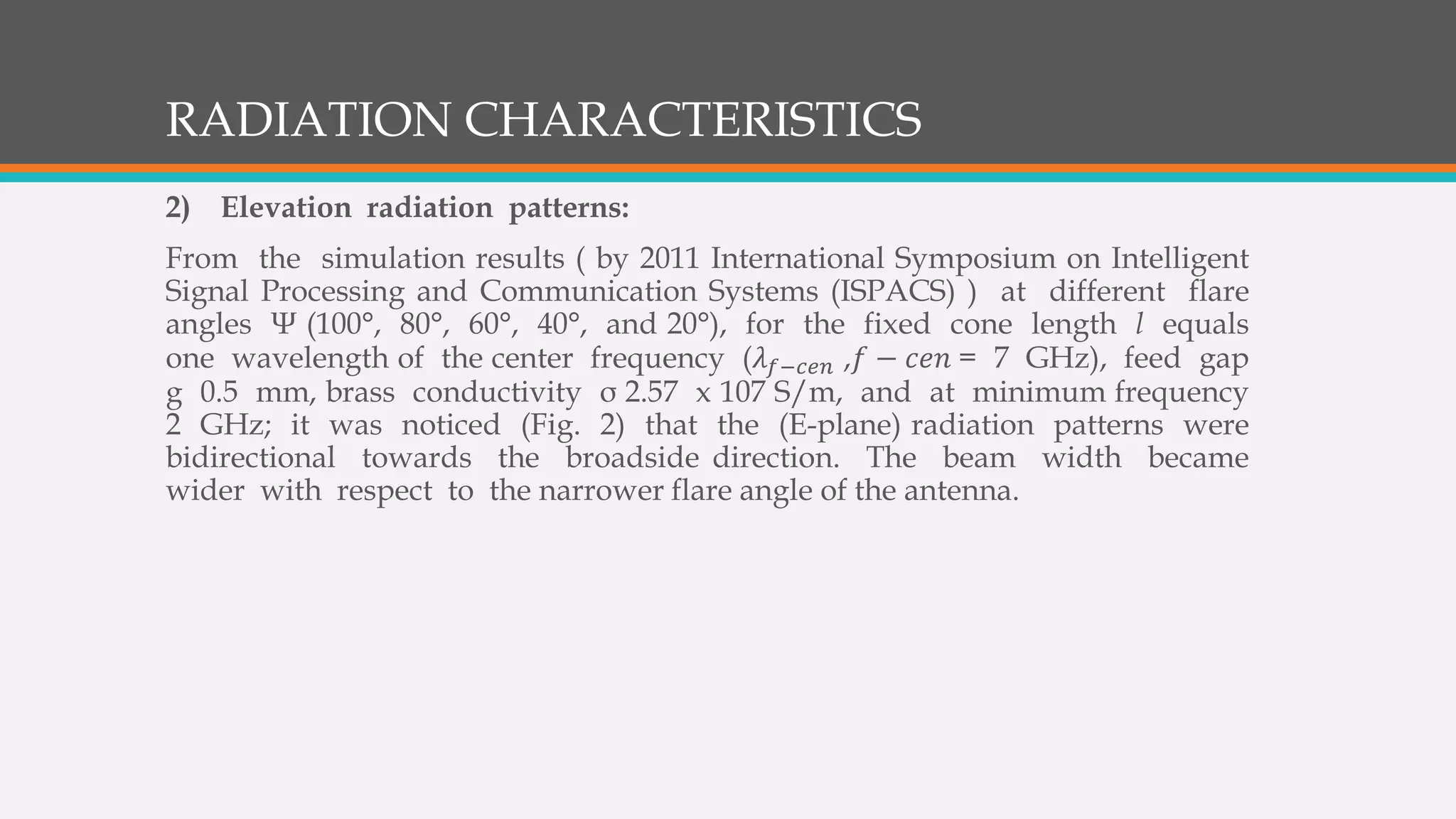
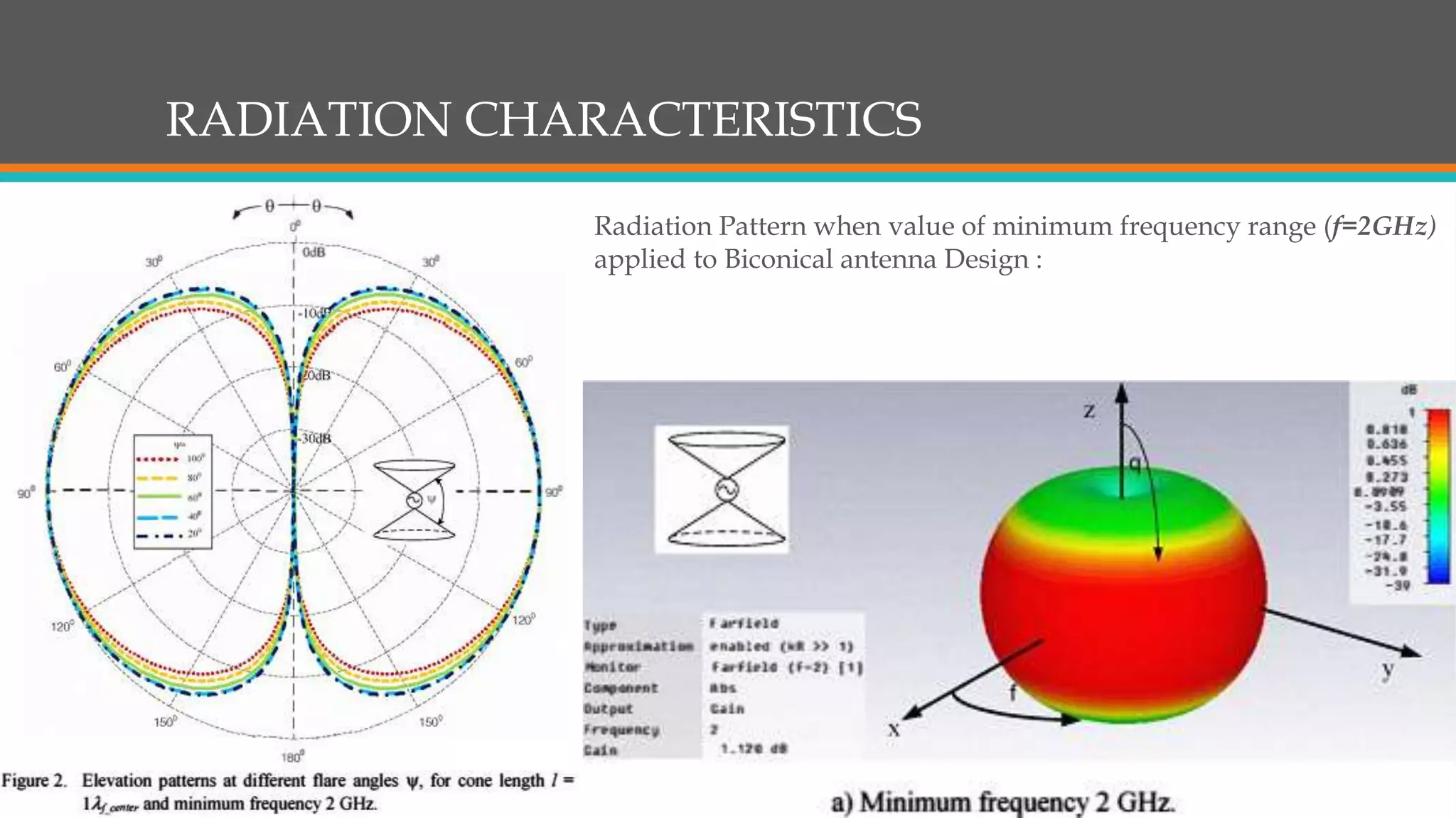
![RADIATION CHARACTERISTICS
1) Azimuth radiation patterns:
from the antenna configuration (Fig. 1)
exhibiting rotational symmetry (around z-axis),
hence the radiation characteristic would also be
symmetrical (omni-directional) in the azimuth
(H-) plane (Fig. 13) [8]-[10].](https://image.slidesharecdn.com/biconicalantenna-140810223804-phpapp01/75/Design-and-Application-of-Biconical-Antenna-7-2048.jpg)
![REFERENCES
[1] First Report and Order in the Matter of Revision of Part 15 of the Commission's Rules Regarding Ultra-Wideband
Transmission Systems, Released by Federal Communications Commission ET-Docket, pp_ 98-153, 2nd Apr. 2002_
[2] C. Yu, W_ Hong, L. Chiu, G_ Zhai C. Yu, W. Qin, and Z. Kuai, "Ultrawideband printed Log-Periodic dipole antenna
with multiple notched bands," IEEE Trans. Antennas Propagat, vol. 59, pp. 725-732, Mar. 2001.
[3] P_ Jirasakulporn and P. Akkaraekthalin, "A conpact ultra-wideband rectanllli lar slot antanna tuned with T -shape fractal
stub," Electrical Engineering Conference-32, vol. 2, pp. 785-788, Oct 2009_ Prachinburi. Thailand_
[4] H. Schantz, The Art and Science of Ultrawideband Antennas, Artech House Publishers, 2005_
[5] C. H. Papas and R. W_ P_ King, "Input impedance of wide angle conical antennas fed by a coaxial line," Proc_ IRE, vol. 37,
pp_ 1269-1271, Nov_
1949.
[6] C. H. Papas, and R. W. P_ King, "Radiation from wide-angle conical antennas fed by a coaxial line," Proc. IRE , vol. 39,
pp.49-51, Jan. 1951.
[7] CST Microwave Studio, User's Manual, 2011.
[8] S_ S. Sandler and R. W_ P. King, "Compact conical antenna for wideband coverage," IEEE Trans Antennas Propagat, vol.
42, no 3, pp. 436-439, Mar_ 1994_
[9] S_ N_ Samadder and E. L. Mokole, "Biconical antenna with unequal cone angles," IEEE Trans_ Antennas Propagat, vol.
46, no 2, pp_ 181-192, Feb_ 1998_
[10] C. Ghosh and T. K. Sarkar, "Design of a wide-angle biconical antenna for wideband communications," Progress in
Electromagnetics Research B, vol. 16, pp_ 229-245, 2009_
[11] H. T_ Friis, "A note on a simple transmission fonnula," Proc_ IRE, vol. 34, no 5, pp_ 254-256, May 1946_](https://image.slidesharecdn.com/biconicalantenna-140810223804-phpapp01/75/Design-and-Application-of-Biconical-Antenna-18-2048.jpg)


The document discusses the biconical antenna, focusing on its design, input impedance, and radiation patterns within the context of ultra-wideband (UWB) wireless communication regulated by the FCC since 2002. It details the antenna's configuration, symmetrical feeding mechanism, and how its radiation patterns vary with changes in cone angles and frequencies. The document also references various studies and simulations related to the performance and characteristics of biconical antennas.