Introduction to Robotics in Mechanical Engineering.pptx
TIPLER CAP r25
1. 333
Chapter 25
Electric Current and Direct-Current Circuits
Conceptual Problems
*1 •
Determine the Concept When current flows, the charges are not in equilibrium. In that
case, the electric field provides the force needed for the charge flow.
2 •
Determine the Concept Water, regarded as a viscous liquid flowing from a water tower
through a pipe to ground is another mechanical analog of a simple circuit.
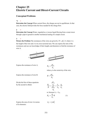
3 •
Picture the Problem The resistances of the wires are given by ,
A
L
R ρ
= where L is
the length of the wire and A is its cross-sectional area. We can express the ratio of the
resistances and use our knowledge of their lengths and diameters to find the resistance of
wire A.
Express the resistance of wire A:
A
A
A
A
L
R
ρ
=
where ρ is the resistivity of the wire.
Express the resistance of wire B:
B
B
A
L
R
ρ
=
Divide the first of these equations
by the second to obtain:
A
B
B
A
B
B
A
A
A
A
A
L
L
A
L
A
L
R
R
⋅
=
=
ρ
ρ
or, because LA = LB,
R
A
A
R
A
B
A = (1)
Express the area of wire A in terms
of its diameter:
2
A
4
1
A d
A π
=
2. Chapter 25
334
Express the area of wire B in terms
of its diameter:
2
B
4
1
B d
A π
=
Substitute in equation (1) to obtain:
R
d
d
R 2
A
2
B
A =
or, because dA = 2dB,
( )
R
R
d
d
R 4
1
2
B
2
B
A
2
=
=
and correct.
is
)
(e
4 ••
Determine the Concept An emf is a source of energy that gives rise to a potential
difference between two points and may result in current flow if there is a conducting path
whereas a potential difference is the consequence of two points in space being at different
potentials.
*5 ••
Picture the Problem The resistance of the
metal bar varies directly with its length and
inversely with its cross-sectional area.
Hence, to minimize the resistance of the
bar, we should connect to the surface for
which the ratio of the length to the contact
area is least.
Denoting the surfaces as a, b, and c,
complete the table to the right:
Surface L A L/A
a 10 8 0.8
b 4 20 0.2
c 2 40 0.05
Because connecting to surface c
minimizes R:
correct.
is
)
(c
6 ••
Picture the Problem The resistances of the wires are given by ,
A
L
R ρ
=
where L is the length of the wire and A is its cross-sectional area. We can express the
ratio of the resistances and use the definition of density to eliminate the cross-sectional
areas of the wires in favor of the ratio of their lengths.
3. `Electric Current and Direct-Current Circuits 335
Express the resistance of wire A:
A
A
A
A
L
R
ρ
=
where ρ is the resistivity of copper.
Express the resistance of wire B:
B
B
B
A
L
R
ρ
=
Divide the first of these equations
by the second to obtain:
A
B
B
A
B
B
A
A
B
A
A
A
L
L
A
L
A
L
R
R
=
=
ρ
ρ
or, because LA = 2LB,
B
A
B
A 2 R
A
A
R = (1)
Using the definition of density,
express the mass of wire A:
A
A
A
A A
'L
'V
m ρ
ρ =
=
where ρ′ is the density of copper.
Express the mass of wire B B
B
B
B A
'L
'V
m ρ
ρ =
=
Because the masses of the wires are
equal:
B
B
A
A A
'L
A
'L ρ
ρ =
or
B
A
A
B
L
L
A
A
=
Substitute in equation (1) to obtain:
( ) B
B
B
B
A
A 4
2
2
2 R
R
R
L
L
R =
=
=
and correct.
is
)
(b
7 •
Picture the Problem The power dissipated in the resistor is given by P = I2
R. We
can express the power dissipated when the current is 3I and, assuming that the
resistance does not change, express the ratio of the two rates of energy dissipation
to find the power dissipated when the current is 3I.
Express the power dissipated in the R
I
P 2
=
4. Chapter 25
336
resistor when the current in it is I:
Express the power dissipated in the
resistor when the current in it is 3I:
( ) R
I
R
I
P' 2
2
9
3 =
=
Divide the second of these
equations by the first to obtain:
9
9
2
2
=
=
R
I
R
I
P
P'
or
P
P' 9
= and correct.
is
)
(d
8 •
Picture the Problem Assuming the current (which depends on the resistance) to
be constant, the power dissipated in a resistor is directly proportional to the
voltage drop across it.
Express the power dissipated in the
resistor when the voltage drop
across it is V:
R
V
P
2
=
Express the power dissipated in the
resistor when the voltage drop
across it is increased to 2V:
( )
R
V
R
V
P'
2
2
4
2
=
=
Divide the second of these equations
by the first to obtain: 4
4
2
2
=
=
R
V
R
V
P
P'
⇒ P
P' 4
=
correct.
is
)
(c
9 •
Determine the Concept You should decrease the resistance. Because the voltage across
the resistor is constant, the heat out is given by R
V
P 2
= . Hence, decreasing the
resistance will increase P.
*10 •
Picture the Problem We can find the equivalent resistance of this two-resistor
combination and then apply the condition that R1 >> R2.
Express the equivalent resistance of
R1 and R2 in parallel: 2
1
eq
1
1
1
R
R
R
+
=
5. `Electric Current and Direct-Current Circuits 337
Solve for Req to obtain:
2
1
2
1
eq
R
R
R
R
R
+
=
Factor R1 from the denominator and
simplify to obtain:
1
2
2
1
2
1
2
1
eq
1
1
R
R
R
R
R
R
R
R
R
+
=
⎟
⎟
⎠
⎞
⎜
⎜
⎝
⎛
+
=
If R1 >> R2, then: 2
eff
eq R
R
R ≈
= and correct
is
)
(b
11 •
Picture the Problem We can find the equivalent resistance of this two-resistor
combination and then apply the condition that R1 >> R2.
Express the equivalent resistance of
R1 and R2 in series:
2
1
eq R
R
R +
=
Factor R1 to obtain:
⎟
⎟
⎠
⎞
⎜
⎜
⎝
⎛
+
=
1
2
1
eq 1
R
R
R
R
If R1 >> R2, then: 1
eff
eq R
R
R ≈
= and correct
is
)
(a
12 •
Picture the Problem Because the potential difference across resistors connected in
parallel is the same for each resistor; we can use Ohm’s law to relate the currents through
the resistors to their resistances.
Using Ohm’s law, express the
current carried by resistor A: B
A
A
2R
V
R
V
I =
=
Using Ohm’s law, express the
current carried by resistor B: B
B
R
V
I =
Divide the second of these equations
by the first to obtain:
2
2 B
B
A
B
=
=
R
V
R
V
I
I
and
A
B 2I
I = and correct.
is
)
(b
6. Chapter 25
338
*13 •
Determine the Concept In a series circuit, because there are no alternative
pathways, all resistors carry the same current. The potential difference across each resistor,
keeping with Ohm’s law, is given by the product of the current and the
resistance and, hence, is not the same across each resistor unless the resistors
are identical. correct.
is
)
(a
14 ••
Picture the Problem Because the potential difference across the two combinations
of resistors is constant, we can use R
V
P 2
= to relate the power delivered by the
battery to the equivalent resistance of each combination of resistors.
Express the power delivered by the
battery when the resistors are
connected in series:
eq
2
s
R
V
P =
Letting R represent the resistance of
the identical resistors, express Req:
R
R
R
R 2
eq =
+
=
Substitute to obtain:
R
V
P
2
2
s = (1)
Express the power delivered by the
battery when the resistors are
connected in parallel:
eq
2
p
R
V
P =
Express the equivalent resistance of
the identical resistors connected in
parallel:
( )( ) R
R
R
R
R
R 2
1
eq =
+
=
Substitute to obtain:
R
V
R
V
P
2
2
1
2
p
2
=
= (2)
Divide equation (2) by equation (1)
to obtain: 4
2
2
2
2
s
p
=
=
R
V
R
V
P
P
Solve for and evaluate Pp: ( ) W
80
W
20
4
4 s
p =
=
= P
P
and correct.
is
)
(e
7. `Electric Current and Direct-Current Circuits 339
15 •
Determine the Concept While Kirchhoff’s loop rule is a statement about potential
differences around a closed loop in a circuit, recall that electric potential at a
point in space is the work required to bring a charged object from infinity to the
given point. Hence, the loop rule is actually a statement that energy is conserved
around any closed path in an electric circuit. correct.
is
)
(b
16 •
Determine the Concept An ideal voltmeter would have infinite resistance. A voltmeter
consists of a galvanometer movement connected in series with a large resistance. The
large resistor accomplishes two purposes; 1) it protects the galvanometer movement by
limiting the current drawn by it, and 2) minimizes the loading of the circuit by the
voltmeter by placing a large resistance in parallel with the circuit element across which
the potential difference is being measured. correct.
is
)
(a
*17 •
Determine the Concept An ideal ammeter would have zero resistance. An ammeter
consists of a very small resistance in parallel with a galvanometer movement. The small
resistance accomplishes two purposes: 1) It protects the galvanometer movement by
shunting most of the current in the circuit around the galvanometer movement, and 2) It
minimizes the loading of the circuit by the ammeter by minimizing the resistance of the
ammeter. correct.
is
)
(b
18 •
Determine the Concept An ideal voltage source would have zero internal resistance.
The terminal potential difference of a voltage source is given by Ir,
V −
= ε where ε is
the emf of the source, I is the current drawn from the source, and r is the internal
resistance of the source. correct.
is
)
(b
19 •
Determine the Concept If we apply Kirchhoff’s loop rule with the switch closed, we
obtain ε − IR – VC = 0. Immediately after the switch is closed, I = 0 and we have ε = VC.
correct.
is
)
(b
20 ••
Determine the Concept The energy stored in the fully charged capacitor is 2
2
1
ε
C
U = .
During the charging process, a total charge Qf = εC flows through the battery. The battery
therefore does work W = Qfε = Cε 2
. The energy dissipated in the resistor is the difference
between W and U. correct.
is
)
(b
8. Chapter 25
340
*21 ••
Determine the Concept Applying Kirchhoff’s loop rule to the circuit, we obtain
0
C =
−
− V
VR
ε , where VR is the voltage drop across the resistor. Applying Ohm’s law to
the resistor, we obtain VR = IR. Because I decreases as the capacitor is charged, VR
decreases with time. correct.
is
)
(e
22 ••
Picture the Problem We can express the variation of charge on the discharging capacitor
as a function of time to find the time T it takes for the charge on the capacitor to drop to
half its initial value. We can also express the energy remaining in the electric field of the
discharging capacitor as a function of time and find the time t′ for the energy to drop to
half its initial value in terms of T.
Express the dependence of the
charge stored on a capacitor on time:
( ) τ
t
e
Q
t
Q −
= 0
where τ = RC.
For Q(t) = ½ Q0: τ
T
e
Q
Q −
= 0
0
2
1
or
τ
T
e−
=
2
1
Take the natural logarithm of both
sides of the equation and solve for T
to obtain:
2
ln
τ
=
T
Express the dependence of the
energy stored in a capacitor on the
potential difference VC across its
terminals:
( ) 2
C
2
1
CV
t
U =
Express the potential difference
across a discharging capacitor as a
function of time:
RC
t
e
V
V −
= 0
C
Substitute to obtain: ( ) ( )
RC
t
RC
t
RC
t
e
U
e
CV
e
V
C
t
U
2
0
2
2
0
2
1
2
0
2
1
−
−
−
=
=
=
For U(t) = ½ U0: RC
t'
e
U
U 2
0
0
2
1 −
=
or
RC
t
e '
2
2
1 −
=
9. `Electric Current and Direct-Current Circuits 341
Take the natural logarithm of both
sides of the equation and solve for t′
to obtain:
T
t' 2
1
2
1
2
ln =
= τ
23 •
Determine the Concept A small resistance because P = ε2
/R.
*24 •
Determine the Concept The potential difference across an external resistor of resistance
R is given by V,
R
r
R
+
where r is the internal resistance and V the voltage supplied by the
source. The higher R is, the higher the voltage drop across R. Put differently, the higher
the resistance a voltage source sees, the less its own resistance will change the circuit.
25 •
Determine the Concept Yes. Kirchhoff’s rules are statements of the conservation of
energy and charge and hence apply to all circuits.
26 ••
Determine the Concept All of the current provided by the battery passes through R1,
whereas only half this current passes through R2 and R3. Because P = I 2
R, the power
dissipated in R1 will be four times that dissipated in R2 and R3. correct.
is
)
(c
Estimation and Approximation
27 ••
Picture the Problem We can use Ohm’s law and the definition of resistivity to find the
maximum voltage that can be applied across 40 m of the 16-gauge copper wire. In part (b)
we can find the electric field in the wire using E = V/L. In part (c) we can use R
I
P 2
= to
find the power dissipated in the wire when it carries 6 A.
(a) Use Ohm’s law to relate the
potential difference across the wire
to its maximum current and its
resistance:
R
I
V max
max =
Use the definition of resistivity to
relate the resistance of the wire to its
length and cross-sectional area:
A
L
R ρ
=
Substitute to obtain:
A
L
I
V ρ
max
max =
10. Chapter 25
342
Substitute numerical values (see
Tables 25-1 and 25-2) for the
resistivity of copper and the cross-
sectional area of 16-gauge wire:
( )( )
V
12
.
3
mm
1.309
m
40
m
Ω
10
1.7
A
6
2
8
max
=
⎟
⎟
⎠
⎞
⎜
⎜
⎝
⎛
×
⋅
×
= −
V
(b) Relate the electric in the wire to
the potential difference between its
ends and the length of the wire:
mV/m
78.0
m
40
V
3.12
=
=
=
L
V
E
(c) Relate the power dissipated in
the wire to the current in and the
resistance of the wire:
R
I
P 2
=
Substitute for R to obtain:
A
L
I
P ρ
2
=
Substitute numerical values and
evaluate P:
( ) ( )
W
7
.
18
mm
1.309
m
40
m
Ω
10
1.7
A
6 2
8
2
=
⎟
⎟
⎠
⎞
⎜
⎜
⎝
⎛
⋅
×
= −
P
28 ••
Picture the Problem We can use the definition of resistivity to find the resistance of the
jumper cable. In part (b), the application of Ohm’s law will yield the potential difference
across the jumper cable when it is starting a car, and, in part (c), we can use the
expression for the power dissipated in a conductor to find the power dissipation in the
jumper cable.
(a) Noting that a jumper cable has
two leads, express the resistance of
the cable in terms of the wire’s
resistivity and the cable’s length,
and cross-sectional area:
A
L
R ρ
=
Substitute numerical values (see
Table 25-1 for the resistivity of
copper) and evaluate R:
( )
Ω
=
⋅
Ω
×
= −
0102
.
0
mm
10
m
6
m
10
7
.
1 2
8
R
(b) Apply Ohm’s law to the cable to
obtain:
( )( ) V
0.918
Ω
0.0102
A
90 =
=
= IR
V
11. `Electric Current and Direct-Current Circuits 343
(c) Use the expression for the power
dissipated in a conductor to obtain:
( )( ) W
82.6
V
0.918
A
90 =
=
= IV
P
29 ••
Picture the Problem We can combine the expression for the rate at which energy is
delivered to the water to vaporize it (P = ε 2
/R) and the expression for the resistance of a
conductor ( A
L
R ρ
= ) to obtain an expression for the required length L of wire.
Use an expression for the power
dissipated in a resistor to relate the
required resistance to rate at which
energy is delivered to generate the
steam:
P
R
2
ε
=
Relate the resistance of the wire to
its length, cross-sectional area, and
resistivity:
A
L
R ρ
=
Equate these two expressions and
solve for L to obtain: P
A
L
ρ
ε2
=
Express the power required to
generate the steam in terms of the
rate of energy delivery:
( )
t
m
L
t
mL
t
E
P
∆
∆
=
∆
∆
=
∆
∆
= v
v
Substitute to obtain:
t
m
L
A
L
∆
∆
=
v
2
ρ
ε
Substitute numerical values (see
Table 25-1 for the resistivity of
Nichrome and Table 18-2 for the
latent heat of vaporization of water)
and evaluate L:
( ) ( )
( )( )( )
m
03
.
2
g/s
8
kJ/kg
2257
m
10
mm
80
.
1
4
V
120
6
2
2
=
⋅
Ω
= −
π
L
*30 ••
Picture the Problem We can find the annual savings by taking into account the costs of
the two types of bulbs, the rate at which they consume energy and the cost of that energy,
and their expected lifetimes.
Express the yearly savings: t
fluorescen
nt
incandesce Cost
Cost
$ −
=
∆ (1)
12. Chapter 25
344
Express the annual cost with the
incandescent bulbs:
energy
bulbs
nt
incandesce Cost
Cost
Cost +
=
Express and evaluate the annual cost of the incandescent bulbs:
( ) ( ) 74
.
65
$
50
.
1
$
h
1200
d
h
24
d
365.24
6
bulb
per
cost
bulbs
of
n
consumptio
annual
use
in
bulbs
of
number
Costbulbs
=
⎟
⎟
⎟
⎟
⎠
⎞
⎜
⎜
⎜
⎜
⎝
⎛
×
=
×
×
=
Find the cost of operating the incandescent bulbs for one year:
( )( )( )( )
64
.
453
$
h
kW
/
115
.
0
$
h/d
24
d
365.25
W
75
6
energy
of
unit
per
cost
consumed
energy
Costenergy
=
⋅
=
×
=
Express the annual cost with the
fluorescent bulbs:
energy
bulbs
t
fluorescen Cost
Cost
Cost +
=
Express and evaluate the annual cost of the fluorescent bulbs:
( ) ( ) 45
.
39
$
6
$
h
8000
d
h
24
d
365.24
6
bulb
per
cost
bulbs
of
n
consumptio
annual
use
in
bulbs
of
number
Costbulbs
=
⎟
⎟
⎟
⎟
⎠
⎞
⎜
⎜
⎜
⎜
⎝
⎛
×
=
×
×
=
Find the cost of operating the fluorescent bulbs for one year:
( ) ( )
97
.
120
$
h
kW
/
115
.
0
$
d
h
24
d
365.24
W
0
2
6
energy
of
unit
per
cost
consumed
energy
Costenergy
=
⋅
⎟
⎠
⎞
⎜
⎝
⎛
×
=
×
=
Substitute in equation (1) and evaluate the cost savings ∆$:
( ) ( )
96
.
358
$
97
.
120
$
45
.
39
$
64
.
453
$
74
.
65
$
Cost
Cost
$ t
fluorescen
nt
incandesce
=
+
−
+
=
−
=
∆
13. `Electric Current and Direct-Current Circuits 345
31 ••
Picture the Problem We can use an expression for the power dissipated in a resistor to
relate the Joule heating in the wire to its resistance and the definition of resistivity to
relate the resistance to the length and cross-sectional area of the wire.
Express the power the wires must
dissipate in terms of the current they
carry and their resistance:
R
I
P 2
=
Divide both sides of the equation by
L to express the power dissipation
per unit length:
L
R
I
L
P 2
=
Using the definition of resistivity,
relate the resistance of the wire to its
resistivity, length and cross-
sectional area:
2
2
4
4
d
L
d
L
A
L
R
π
ρ
ρ
ρ π
=
=
=
Substitute to obtain:
2
2
4
d
I
L
P
π
ρ
=
Solve for d to obtain:
( )
L
P
I
d
/
2
π
ρ
=
Substitute numerical values (see
Table 25-1 for the resistivity of
copper wire) and evaluate d:
( )
( )
mm
08
.
2
W/m
2
m
10
7
.
1
A
20
2
8
=
⋅
Ω
×
=
−
π
d
*32 ••
Picture the Problem Let r be the internal resistance of each battery and use Ohm’s law
to express the current in laser diode as a function of the potential difference across r. We
can find the power of the laser diode from the product of the potential difference across
the internal resistance of the batteries and the current delivered by them I and the time-to-
discharge from the combined capacities of the two batteries and I.
(a) Use Ohm’s law to express the current
in the laser diode: r
V
I
2
resistance
internal
=
The potential difference across the internal
resistance is:
V
3
.
2
resistance
internal −
= ε
V
14. Chapter 25
346
Substitute to obtain:
r
I
2
V
3
.
2
−
=
ε
Assuming that r = 125 Ω: ( )
( )
mA
20
.
3
125
2
V
3
.
2
55
.
1
2
=
Ω
−
=
I
(b) The power delivered by the batteries is
given by:
( )( ) mW
36
.
7
V
3
.
2
mA
2
.
3 =
=
= IV
P
The power of the laser is half this
value:
( ) mW
68
.
3
mW
36
.
7
2
1
2
1
laser =
=
= P
P
Express the ratio of Plaser to Pquoted:
23
.
1
mW
3
mW
68
.
3
quoted
laser
=
=
P
P
or
quoted
laser %
123 P
P =
(c) Express the time-to-discharge:
I
t
Capacity
=
∆
Because each battery has a capacity
of 20 mA⋅h, the series combination
has a capacity of
40 mA⋅h and:
h
5
.
12
mA
20
.
3
h
mA
40
=
⋅
=
∆t
Current and the Motion of Charges
33 •
Picture the Problem We can relate the drift velocity of the electrons to the current density
using A
nev
I d
= . We can find the number density of charge carriers n using
,
M
N
n A
ρ
= where ρ is the mass density, NA Avogadro’s number, and M the molar
mass. We can find the cross-sectional area of 10-gauge wire in Table 25-2.
Use the relation between current and
drift velocity to relate I and n:
A
nev
I d
=
Solve for vd:
neA
I
v =
d
15. `Electric Current and Direct-Current Circuits 347
The number density of charge
carriers n is related to the mass
density ρ, Avogadro’s number NA,
and the molar mass M:
M
N
n A
ρ
=
For copper, ρ = 8.93 g/cm3
and
M = 63.5 g/mol. Substitute and
evaluate n:
( )( )
3
28
23
3
atoms/m
10
47
.
8
g/mol
63.5
atoms/mol
10
6.02
g/cm
8.93
×
=
×
=
n
Using Table 25-2, find the cross-
sectional area A of 10-gauge wire:
2
mm
261
.
5
=
A
Substitute and evaluate vd:
( )( )( ) mm/s
281
.
0
mm
261
.
5
C
10
60
.
1
m
10
47
.
8
A
20
2
19
3
28
d =
×
×
= −
−
v
34 •
Picture the Problem Note that, while the positive and negative charges flow in opposite
directions, the total current is their sum.
Express the total current I in the
tube as the sum of the electron
current and the ion current:
ion
electron I
I
I +
=
The electron current is the product
of the number of electrons through
the cross-sectional area each second
and the charge of each electron:
( )
( )
A
320
.
0
C/electron
10
60
.
1
s
electrons/
10
2
19
18
electron
=
×
×
×
=
=
−
ne
I
Proceed in the same manner to find
the ion current: ( )
( )
A
0800
.
0
C/electron
10
60
.
1
s
electrons/
10
5
.
0
19
18
ion
ion
ion
=
×
×
×
=
=
−
q
n
I
Substitute to obtain: A
400
.
0
A
0.0800
A
320
.
0 =
+
=
I
35 •
Picture the Problem We can solve 2
e
2
1
v
m
K = for the velocity of an electron in the
beam and use the relationship between current and drift velocity to find the beam current.
16. Chapter 25
348
(a) Express the kinetic energy of the
beam:
2
e
2
1
v
m
K =
Solve for v:
e
2
m
K
v =
Substitute numerical values and
evaluate v:
( )( )
m/s
10
93
.
5
kg
10
11
.
9
J/eV
10
60
.
1
keV
10
2
7
31
19
×
=
×
×
= −
−
v
(b) Use the relationship between
current and drift velocity (here the
velocity of an electron in the beam)
to obtain:
A
nev
I d
=
Express the cross-sectional area of
the beam in terms of its diameter D:
2
4
1
D
A π
=
Substitute to obtain: 2
d
4
1
D
nev
I π
=
Substitute numerical values and
evaluate I:
Substitute numerical values and evaluate I:
( )( )( )( ) A
3
.
37
m
10
m/s
10
93
.
5
C
10
60
.
1
cm
10
5
2
3
7
19
3
6
4
1
µ
π =
×
×
×
= −
−
−
I
36 ••
Picture the Problem We can use the definition of current, the definition of charge
density, and the relationship between period and frequency to derive an expression for
the current as a function of a, λ, and ω.
Use the definition of current to
relate the charge ∆Q associated with
a segment of the ring to the time ∆t
it takes the segment to pass a given
point:
t
Q
I
∆
∆
=
Because each segment carries a
charge ∆Q and the time for one
Qf
T
Q
I ∆
=
∆
= (1)
17. `Electric Current and Direct-Current Circuits 349
revolution is T:
Use the definition of the charge
density λ to relate the charge ∆Q to
the radius a of the ring:
a
Q
π
λ
2
∆
=
Solve for ∆Q to obtain: λ
πa
Q 2
=
∆
Substitute in equation (1) to obtain: f
a
I λ
π
2
=
Because f
π
ω 2
= we have: λω
a
I =
*37 ••
Picture the Problem The current will be the same in the two wires and we can relate the
drift velocity of the electrons in each wire to their current densities and the cross-
sectional areas of the wires. We can find the number density of charge carriers n using
,
M
N
n A
ρ
= where ρ is the mass density, NA Avogadro’s number, and M the molar
mass. We can find the cross-sectional area of 10- and 14-gauge wires in Table 25-2.
Relate the current density to the drift
velocity of the electrons in the 10-
gauge wire:
d
gauge
10
gauge
10
nev
A
I
=
Solve for vd:
gauge
10
gauge
10
10
d,
neA
I
v =
The number density of charge
carriers n is related to the mass
density ρ, Avogadro’s number NA,
and the molar mass M:
M
N
n A
ρ
=
For copper, ρ = 8.93 g/cm3
and
M = 63.5 g/mol. Substitute and
evaluate n:
( )( )
3
28
23
3
atoms/m
10
47
.
8
g/mol
63.5
atoms/mol
10
6.02
g/cm
8.93
×
=
×
=
n
Use Table 25-2 to find the cross-
sectional area of 10-gauge wire:
2
10 mm
261
.
5
=
A
Substitute numerical values and evaluate vd.10:
18. Chapter 25
350
( )( )( ) mm/s
210
.
0
mm
261
.
5
C
10
60
.
1
m
10
47
.
8
A
15
2
19
3
28
10
d, =
×
×
= −
−
v
Express the continuity of the current
in the two wires:
gauge
14
gauge
10 I
I =
or
gauge
14
d,14
gauge
10
d,10 A
nev
A
nev =
Solve for vd,14 to obtain:
gauge
14
gauge
10
d,10
d,14
A
A
v
v =
Use Table 25-2 to find the cross-
sectional area of 14-gauge wire:
2
14 mm
081
.
2
=
A
Substitute numerical values and
evaluate vd,14:
( )
mm/s
531
.
0
mm
2.081
mm
5.261
mm/s
0.210 2
2
d,14
=
=
v
38 ••
Picture the Problem We can use neAv
I = to relate the number n of protons per unit
volume in the beam to current I. We can find the speed of the particles in the beam from
their kinetic energy. In part (b) we can express the number of protons N striking the target
per unit time as the product of the number of protons per unit volume n in the beam and
the volume of the cylinder containing those protons that will strike the target in an elapsed
time ∆t and solve for N. Finally, we can use the definition of current to express the charge
arriving at the target as a function of time.
(a) Use the relation between current
and drift velocity to relate I and n:
neAv
I =
Solve for n to obtain:
eAv
I
n =
Express the kinetic energy of the
protons and solve for v:
2
p
2
1
v
m
K = ⇒
p
2
m
K
v =
Relate the cross-sectional area A of
the beam to its diameter D:
2
4
1
D
A π
=
19. `Electric Current and Direct-Current Circuits 351
Substitute for v and A to obtain:
K
m
eD
I
m
K
eD
I
n
2
4
2
p
2
p
2
4
1
π
π
=
=
Substitute numerical values and evaluate n:
( )
( )( ) ( )( )
3
13
19
27
2
19
mm
10
21
.
3
J/eV
10
60
.
1
MeV
20
2
kg
10
67
.
1
mm
2
C
10
60
.
1
mA
1
4 −
−
−
−
×
=
×
×
×
=
π
n
(b) Express the number of protons N
striking the target per unit time as the
product of the number n of protons
per unit volume in the beam and the
volume of the cylinder containing
those protons that will strike the
target in an elapsed time ∆t and solve
for N:
( )
vA
n
t
N
=
∆
⇒ t
nvA
N ∆
=
Substitute for v and A to obtain:
p
2
4
1
2
m
K
t
n
D
N ∆
= π
Substitute numerical values and evaluate N:
( ) ( )( ) ( )( ) 17
27
19
3
13
2
4
1
10
75
.
3
kg
10
67
.
1
J/eV
10
60
.
1
MeV
20
2
min
1
m
10
21
.
3
mm
2 ×
=
×
×
×
= −
−
−
π
N
(c) Using the definition of current,
express the charge arriving at the
target as a function of time:
( )
( )t
t
It
Q
mC/s
1
mA
1
=
=
=
*39 ••
Picture the Problem We can relate the number of protons per meter N to the number n of
free charge-carrying particles per unit volume in a beam of cross-sectional area A and then
use the relation between current and drift velocity to relate n to I.
(a) Express the number of protons
per meter N in terms of the number
n of free charge-carrying particles
per unit volume in a beam of cross-
nA
N = (1)
20. Chapter 25
352
sectional area A:
Use the relation between current and
drift velocity to relate I and n:
enAv
I =
Solve for n to obtain:
eAv
I
n =
Substitute to obtain:
ev
I
eAv
IA
N =
=
Substitute numerical values and
evaluate N: ( )( )
1
8
8
19
m
10
04
.
1
m/s
10
3
C
10
1.60
mA
5
−
−
×
=
×
×
=
N
(b) From equation (1) we have:
3
14
2
6
1
8
m
10
1.04
m
10
m
10
1.04
−
−
−
×
=
×
=
=
A
N
n
Resistance and Ohm’s Law
40 •
Picture the Problem We can use Ohm’s law to find the potential difference between the
ends of the wire and V = EL to find the magnitude of the electric field in the wire.
(a) Apply Ohm’s law to obtain: ( )( ) V
00
.
1
A
5
2
.
0 =
Ω
=
= RI
V
(b) Relate the electric field to the
potential difference across the wire
and the length of the wire:
V/m
0.100
m
10
V
1
=
=
=
L
V
E
41 •
Picture the Problem We can apply Ohm’s law to both parts of this problem, solving first
for R and then for I.
(a) Apply Ohm’s law to obtain:
Ω
=
=
= 3
.
33
A
3
V
100
I
V
R
21. `Electric Current and Direct-Current Circuits 353
(b) Apply Ohm’s law a second time
to obtain:
A
0.751
Ω
33.3
V
25
=
=
=
R
V
I
42 •
Picture the Problem We can use A
L
R ρ
= to find the resistance of the block and
Ohm’s law to find the current in it for the given potential difference across its length.
(a) Relate the resistance of the block
to its resistivity ρ, cross-sectional
area A, and length L:
A
L
R ρ
=
Substitute numerical values (see
Table 2625-1 for the resistivity of
carbon) and evaluate R:
( )
( )
Ω
=
⋅
Ω
×
= −
m
0
.
42
cm
0.5
cm
3
m
10
3500 2
8
R
(b) Apply Ohm’s law to obtain:
A
200
mΩ
42.0
V
8.4
=
=
=
R
V
I
43 •
Picture the Problem We can solve the relation A
L
R ρ
= for L to find the length of the
carbon rod that will have a resistance of 10 Ω.
Relate the resistance of the rod to its
resistivity ρ, cross-sectional area A,
and length L:
A
L
R ρ
=
Solve for L to obtain:
ρ
π
ρ
R
r
AR
L
2
=
=
Substitute numerical values (see
Table 2625-1 for the resistivity of
carbon) and evaluate L:
( ) ( ) mm
98
.
8
m
10
3500
10
mm
1
.
0
8
2
=
⋅
Ω
×
Ω
= −
π
L
*44 •
Picture the Problem We can use A
L
R ρ
= to find the resistance of the track.
(a) Relate the resistance of the track
to its resistivity ρ, cross-sectional
area A, and length L:
A
L
R ρ
=
22. Chapter 25
354
Substitute numerical values and
evaluate R:
( ) Ω
=
⋅
Ω
= −
182
.
0
cm
55
km
0
1
m
10 2
7
R
45 •
Picture the Problem We can use Ohm’s law in conjunction with A
L
R ρ
= to find the
potential difference across one wire of the extension cord.
Using Ohm’s law, express the
potential difference across one wire
of the extension cord:
IR
V =
Relate the resistance of the wire to
its resistivity ρ, cross-sectional area
A, and length L:
A
L
R ρ
=
Substitute to obtain:
A
LI
V ρ
=
Substitute numerical values (see
Table 25-1 for the resistivity of
copper and Table 25-2 for the cross-
sectional area of 16-gauge wire) and
evaluate V:
( )( )( )
V
95
.
1
mm
1.309
A
5
m
30
m
10
7
.
1 2
8
=
⋅
Ω
×
= −
V
46 •
Picture the Problem We can use A
L
R ρ
= to find the length of a 14-gauge copper wire
that has a resistance of 2 Ω.
(a) Relate the resistance of the wire
to its resistivity ρ, cross-sectional
area A, and length L:
A
L
R ρ
=
Solve for L to obtain:
ρ
RA
L =
Substitute numerical values (see
Table 2625-1 for the resistivity of
copper and Table 2625-2 for the
cross-sectional area of 14-gauge
wire) and evaluate L:
( )( ) m
245
m
10
7
.
1
mm
081
.
2
2
8
2
=
⋅
Ω
×
Ω
= −
L
23. `Electric Current and Direct-Current Circuits 355
47 ••
Picture the Problem We can use A
L
R ρ
= to express the resistances of the glass
cylinder and the copper wire. Expressing their ratio will eliminate the common cross-
sectional areas and leave us with an expression we can solve for the length of the copper
wire.
Relate the resistance of the glass
cylinder to its resistivity, cross-
sectional area, and length:
glass
glass
glass
glass
A
L
R ρ
=
Relate the resistance of the copper
wire to its resistivity, cross-
sectional area, and length:
Cu
Cu
Cu
Cu
A
L
R ρ
=
Divide the second of these
equations by the first to obtain:
glass
Cu
glass
Cu
glass
glass
glass
Cu
Cu
Cu
glass
Cu
L
L
A
L
A
L
R
R
⋅
=
=
ρ
ρ
ρ
ρ
or, because Aglass = ACu and RCu = Rglass,
glass
Cu
glass
Cu
1
L
L
⋅
=
ρ
ρ
Solve for LCu to obtain:
glass
Cu
glass
Cu L
L
ρ
ρ
=
Substitute numerical values (see Table 25-
1 for the resistivities of glass and copper)
and evaluate LCu:
( )
y
c
62.2
m
10
9.461
y
c
1
m
10
88
.
5
cm
1
m
10
7
.
1
m
10
15
17
8
12
Cu
⋅
=
×
⋅
×
×
=
⋅
Ω
×
⋅
Ω
= −
L
24. Chapter 25
356
48 ••
Picture the Problem We can use Ohm’s law to relate the potential differences across the
two wires to their resistances and A
L
R ρ
= to relate their resistances to their lengths,
resistivities, and cross-sectional areas. Once we’ve found the potential differences across
each wire, we can use L
V
E = to find the electric field in each wire.
(b) Apply Ohm’s law to express the
potential drop across each wire:
Cu
Cu IR
V =
and
Fe
Fe IR
V =
Relate the resistances of the wires to
their resistivity, cross-sectional area,
and length:
Cu
Cu
Cu
Cu
A
L
R ρ
=
and
Fe
Fe
Fe
Fe
A
L
R ρ
=
Substitute to obtain:
I
A
L
V
Cu
Cu
Cu
Cu
ρ
=
and
I
A
L
V
Fe
Fe
Fe
Fe
ρ
=
Substitute numerical values (see
Table 2625-1 for the resistivities of
copper and iron) and evaluate the
potential differences:
( )( )
( )
( )
V
.46
3
A
2
mm
1
m
80
m
10
7
.
1
2
4
1
8
Cu
=
⋅
Ω
×
=
−
π
V
and
( )( )
( )
( )
V
5
.
12
A
2
mm
1
m
49
m
10
10
2
4
1
8
Fe
=
⋅
Ω
×
=
−
π
V
(a) Express the electric field in each
conductor in terms of its length and
the potential difference across it:
Cu
Cu
Cu
L
V
E =
and
Fe
Fe
Fe
L
V
E =
Substitute numerical values and
evaluate the electric fields:
mV/m
3
.
43
m
80
V
46
.
3
Cu =
=
E
25. `Electric Current and Direct-Current Circuits 357
and
mV/m
255
m
49
V
5
.
12
Fe =
=
E
*49 ••
Picture the Problem We can use Ohm’s law to express the ratio of the potential
differences across the two wires and A
L
R ρ
= to relate the resistances of the wires to
their lengths, resistivities, and cross-sectional areas. Once we’ve found the ratio of the
potential differences across the wires, we can use L
V
E = to decide which wire has the
greater electric field.
(a) Apply Ohm’s law to express the
potential drop across each wire:
Cu
Cu IR
V =
and
Fe
Fe IR
V =
Divide the first of these equations
by the second to express the ratio of
the potential drops across the wires:
Fe
Cu
Fe
Cu
Fe
Cu
R
R
IR
IR
V
V
=
= (1)
Relate the resistances of the wires to
their resistivity, cross-sectional area,
and length:
Cu
Cu
Cu
Cu
A
L
R ρ
=
and
Fe
Fe
Fe
Fe
A
L
R ρ
=
Divide the first of these equations
by the second to express the ratio of
the resistances of the wires: Fe
Cu
Fe
Fe
Fe
Cu
Cu
Cu
Fe
Cu
ρ
ρ
ρ
ρ
=
=
A
L
A
L
R
R
because LCu = LFe and ACu = AFe.
Substitute in equation (1) to obtain:
Fe
Cu
Fe
Cu
ρ
ρ
=
V
V
Substitute numerical values (see
Table 2625-1 for the resistivities of
copper and iron) and evaluate the
ratio of the potential differences:
170
.
0
m
10
10
m
10
7
.
1
8
8
Fe
Cu
=
⋅
Ω
×
⋅
Ω
×
= −
−
V
V
26. Chapter 25
358
(b) Express the electric field in each
conductor in terms of its length and
the potential difference across it:
Cu
Cu
Cu
L
V
E = and
Fe
Fe
Fe
L
V
E =
Divide the first of these equations
by the second to obtain:
170
.
0
Fe
Cu
Cu
Cu
Cu
Cu
Fe
Cu
=
=
=
V
V
L
V
L
V
E
E
or
Cu
Cu
Fe 88
.
5
17
.
0
E
E
E =
=
Because EFe = 5.88ECu: iron wire.
in the
greater
is
E
50 ••
Picture the Problem We can use A
L
R ρ
= to relate the resistance of the salt solution to
its length, resistivity, and cross-sectional area. To find the resistance of the filled tube
when it is uniformly stretched to a length of 2 m, we can use the fact that the volume of
the solution is unchanged to relate the new cross-sectional area of the solution to its
original cross-sectional area.
(a) Relate the resistance of the filled
tube to the resistivity, cross-
sectional area, and length of the salt
solution:
A
L
R ρ
=
Substitute numerical values and
evaluate R:
( )
( )
Ω
=
⋅
Ω
= −
6
.
79
mm
2
m
1
m
10 2
3
π
R
(b) Relate the resistance of the
stretched tube to the resistivity,
cross-sectional area, and length of
the salt solution:
A'
L
A'
L'
R'
2
ρ
ρ =
= (1)
Letting V represent volume, express
the relationship between the before-
stretching volume V and the after-
stretching volume V′:
V'
V =
or
L'A'
LA =
Solve for A′ to obtain:
A
A
L'
L
A' 2
1
=
=
27. `Electric Current and Direct-Current Circuits 359
Substitute in equation (1) to obtain:
( ) Ω
=
Ω
=
⎟
⎠
⎞
⎜
⎝
⎛
=
=
318
6
.
79
4
4
2
2
1
A
L
A
L
R' ρ
ρ
51 ••
Picture the Problem We can use A
L
R ρ
= to relate the resistance of the wires to their
lengths, resistivities, and cross-sectional areas. To find the resistance of the stretched wire,
we can use the fact that the volume of the wire does not change during the stretching
process to relate the new cross-sectional area of the wire to its original cross-sectional
area.
Relate the resistance of the
unstretched wire to its resistivity,
cross-sectional area, and length:
A
L
R ρ
=
Relate the resistance of the stretched
wire to its resistivity, cross-sectional
area, and length:
A'
L'
R' ρ
=
Divide the second of these equations
by the first to obtain:
A'
A
L
L'
A
L
A'
L'
R
R'
=
=
ρ
ρ
or
R
A'
A
R' 2
= (1)
Letting V represent volume, express
the relationship between the before-
stretching volume V and the after-
stretching volume V′:
V'
V =
or
L'A'
LA =
Solve for A/A′ to obtain:
2
=
=
L
L'
A'
A
Substitute in equation (1) to obtain: ( ) ( ) Ω
=
Ω
=
=
= 20
.
1
3
.
0
4
4
2
2 R
R
R'
28. Chapter 25
360
52 ••
Picture the Problem We can use A
L
R ρ
= to find the resistance of the wire from its
length, resistivity, and cross-sectional area. The electric field can be found using E = V/L
and Ohm’s law to eliminate V. The time for an electron to travel the length of the wire can
be found from L = vd∆t, with vd expressed in term of I using d
neAv
I = .
(a) Relate the resistance of the
unstretched wire to its resistivity,
cross-sectional area, and length:
A
L
R ρ
=
Substitute numerical values (see
Table 25-1 for the resistivity of
copper and Table 25-2 for the cross-
sectional area of 10-gauge wire) and
evaluate R:
( )
Ω
=
⋅
Ω
×
= −
323
.
0
mm
5.261
m
100
m
10
7
.
1 2
8
R
(b) Relate the electric field in the
wire to the potential difference
between its ends:
L
V
E =
Use Ohm’s law to obtain:
L
IR
E =
Substitute numerical values and
evaluate E:
( )( ) mV/m
96.9
m
100
Ω
0.323
A
30
=
=
E
(c) Express the time ∆t for an
electron to travel a distance L in the
wire in terms of its drift speed vd:
d
v
L
t =
∆
Relate the current in the wire to the
drift speed of the charge carriers:
d
neAv
I =
Solve for vd to obtain:
neA
I
v =
d
Substitute to obtain:
I
neAL
t =
∆
Substitute numerical values (in Example 25-1 it is shown that n = 8.47×1028
m−3
) and
evaluate ∆t:
29. `Electric Current and Direct-Current Circuits 361
( )( )( )( ) s
10
38
.
2
A
30
m
100
mm
5.261
C
10
1.6
m
10
8.47 5
2
19
3
28
×
=
×
×
=
∆
−
−
t
53 ••
Picture the Problem We can use A
L
R ρ
= to find express the resistance of the wire
from in terms of its length, resistivity, and cross-sectional area. The fact that the volume of
the copper does not change as the cube is drawn out to form the wire will allow us to
eliminate either the length or the cross-sectional area of the wire and solve for its
resistance.
Express the resistance of the wire in
terms of its resistivity, cross-
sectional area, and length:
A
L
R ρ
=
Relate the volume V of the wire to
its length and cross-sectional area:
AL
V =
Solve for L to obtain:
A
V
L =
Substitute to obtain:
2
A
V
R ρ
=
Substitute numerical values (see
Table 25-1 for the resistivity of
copper and Table 25-2 for the cross-
sectional area of 14-gauge wire) and
evaluate R:
( ) ( )
( )
Ω
=
⋅
Ω
×
= −
0314
.
0
mm
081
.
2
cm
2
m
10
7
.
1 2
2
3
8
R
*54 ••
A spreadsheet program to plot I as a function of V is shown below. The formulas used to
calculate the quantities in the columns are as follows:
Cell Content/Formula Algebraic Form
B1 2 I0
A5 −200 V (mV)
A6 A5 + 25 V + ∆V
B5 $B$1*(EXP(A5/25) − 1) ( )
1
mV
25
/
0 −
V
e
I
A B C
1 I_0= 2 nA
2
3 V I
30. Chapter 25
362
4 (mV) (nA)
5 −200.0 −2.00
6 −175.0 −2.00
7 −150.0 −2.00
15 50.0 12.78
16 75.0 38.17
17 100.0 107.20
The following graph was plotted using the data in spreadsheet table shown above.
-10
10
30
50
70
90
110
-200 -150 -100 -50 0 50 100
V (mV)
I
(nA)
A spreadsheet program to plot ln(I) as a function of V for V > 0.3 V follows. The
formulas used to calculate the quantities in the columns are as follows:
Cell Content/Formula Algebraic Form
B1 2 2 nA
A5 300 V
A6 A5 + 10 V + ∆V
B5 LN($B$1*(EXP(A5/25) − 1)) ( )
[ ]
1
ln mV
25
/
0 −
V
e
I
A B C
I_0= 2 nA
V ln(I)
(mV)
300 12.69
310 13.09
320 13.49
330 13.89
340 14.29
350 14.69
970 39.49
31. `Electric Current and Direct-Current Circuits 363
980 39.89
990 40.29
1000 40.69
A graph of ln(I) as a function of V follows. Microsoft Excel’s Trendline feature was used
to obtain the equation of the line.
ln(I ) = 0.04V + 0.6931
0
5
10
15
20
25
30
35
40
45
300 400 500 600 700 800 900 1000
V (mV)
ln(I
)
For V >> 25 mV: mV
25
/
mV
25
/
1 V
V
e
e ≈
−
and
mV
25
/
0
V
e
I
I ≈
Take the natural logarithm of both
sides of the equation to obtain:
( ) ( )
( ) V
I
e
I
I V
mV
25
1
ln
ln
ln
0
mV
25
/
0
+
=
=
which is of the form y = mx + b,
where
( ) 1
mV
04
.
0
mV
25
1 −
=
=
m
in agreement with our graphical result.
55 ••
Picture the Problem We can use the first graph plotted in Problem 55 to conclude that,
if V < 0.5 V, then the diode’s resistance is effectively infinite. We can use Ohm’s law to
estimate the current through the diode.
(a)
.
resistance
infinite
y
essentiall
has
diode
the
and
negligible
is
current
the
then
V,
0.5
if
that,
see
we
55
Problem
in
plotted
graph
first
the
From <
V
(b) Use Ohm’s law to express the
current flowing through the diode:
R
V
I resistor
=
32. Chapter 25
364
For a potential difference across the
diode of approximately
0.5 V:
mA
0
.
90
50
V
0.5
-
V
5
=
Ω
=
I
56 •••
Picture the Problem We can use, as our element of resistance, a semicircular strip of
width t, radius r, and thickness dr. Then ( )dr
t
r
dR ρ
π
= . Because the strips are in
parallel, integrating over them will give us the reciprocal of the resistance of half ring.
Integrate dR from r = a to r = b to
obtain:
⎟
⎠
⎞
⎜
⎝
⎛
=
= ∫ a
b
t
r
dr
t
R
b
a
ln
1
πρ
πρ
Take the reciprocal of both sides of
the equation to obtain:
⎟
⎠
⎞
⎜
⎝
⎛
=
a
b
t
R
ln
ρπ
57 •••
Picture the Problem The element of resistance we use is a segment of length dx and
cross-sectional area π[a + (b − a)x/L]2
. Because these resistance elements are in series,
integrating over them will yield the resistance of the wire.
Express the resistance of the chosen
element of resistance: ( )( )
[ ]
dx
L
x
a
b
a
A
dx
dR 2
−
+
=
=
π
ρ
ρ
Integrate dR from x = 0 to x = L and
simplify to obtain: ( )( )
[ ]
( ) ( )
( )
( )
ab
L
ab
a
b
a
b
L
b
a
a
b
L
a
b
a
a
a
b
L
L
x
a
b
a
dx
R
L
π
ρ
π
ρ
π
ρ
π
ρ
π
ρ
=
⎟
⎠
⎞
⎜
⎝
⎛ −
−
=
⎟
⎠
⎞
⎜
⎝
⎛
−
−
=
⎟
⎟
⎠
⎞
⎜
⎜
⎝
⎛
−
+
−
−
=
−
+
= ∫
1
1
1
1
0
2
33. `Electric Current and Direct-Current Circuits 365
*58 •••
Picture the Problem The diagram shows a
cross-sectional view of the concentric
spheres of radii a and b as well as a
spherical-shell element of radius r. Using
the Hint we can express the resistance dR
of the spherical-shell element and then
integrate over the volume filled with the
material whose resistivity ρ is given to find
the resistance between the conductors.
Note that the elements of resistance are in
series.
Express the element of resistance
dR:
2
4 r
dr
A
dr
dR
π
ρ
ρ =
=
Integrate dR from r = a to r = b to
obtain:
⎟
⎠
⎞
⎜
⎝
⎛
−
=
= ∫ b
a
r
dr
R
b
a
1
1
4
4 2
π
ρ
π
ρ
Substitute numerical values and
evaluate R:
Ω
×
=
⎟
⎟
⎠
⎞
⎜
⎜
⎝
⎛
−
⋅
Ω
=
9
9
10
71
.
3
cm
5
1
cm
5
.
1
1
4
m
10
π
R
59 •••
Picture the Problem The diagram shows a
cross-sectional view of the coaxial
cylinders of radii a and b as well as a
cylindrical-shell element of radius r. We
can express the resistance dR of the
cylindrical-shell element and then integrate
over the volume filled with the material
whose resistivity ρ is given to find the
resistance between the two cylinders. Note
that the elements of resistance are in series.
Express the element of resistance
dR: rL
dr
A
dr
dR
π
ρ
ρ
2
=
=
Integrate dR from r = a to r = b to
obtain:
⎟
⎠
⎞
⎜
⎝
⎛
=
= ∫ a
b
L
r
dr
L
R
b
a
ln
2
2 π
ρ
π
ρ
34. Chapter 25
366
(b) Apply Ohm’s law to obtain:
⎟
⎠
⎞
⎜
⎝
⎛
=
⎟
⎠
⎞
⎜
⎝
⎛
=
=
a
b
LV
a
b
L
V
R
V
I
ln
2
ln
2
ρ
π
π
ρ
Substitute numerical values and
evaluate I:
( )( )
( )
A
05
.
2
cm
1.5
cm
2.5
ln
m
30
V
10
cm
50
2
=
⎟
⎟
⎠
⎞
⎜
⎜
⎝
⎛
⋅
Ω
=
π
I
Temperature Dependence of Resistance
*60 •
Picture the Problem We can use R = ρL/A to find the resistance of the rod at 20°C.
Ignoring the effects of thermal expansion, we can we apply the equation defining the
temperature coefficient of resistivity, α, to relate the resistance at 40°C to the resistance at
20°C.
(a) Express the resistance of the rod
at 20°C as a function of its
resistivity, length, and cross-
sectional area:
A
L
R 20
20 ρ
=
Substitute numerical values and
evaluate R20:
( )
( )
Ω
=
⋅
Ω
×
= −
m
5
.
27
mm
1
m
5
.
0
m
10
5
.
5 2
8
20
R
(b) Express the resistance of the rod
at 40°C as a function of its
resistance at 20°C and the
temperature coefficient of resistivity
α:
( )
[ ]
( )
( )
[ ]
°
−
+
=
°
−
+
=
°
−
+
=
=
C
20
1
C
20
C
20
1
C
20
C
20
20
C
20
40
40
t
R
t
A
L
A
L
A
L
t
A
L
R
α
α
ρ
ρ
α
ρ
ρ
Substitute numerical values (see Table 25-1 for the temperature coefficient of resistivity
of tungsten) and evaluate R40:
( ) ( )( )
[ ] Ω
=
°
×
+
Ω
= −
−
m
0
.
30
C
20
K
10
5
.
4
1
m
5
.
27 1
3
40
R
35. `Electric Current and Direct-Current Circuits 367
61 •
Picture the Problem The resistance of the copper wire increases with temperature
according to ( )
[ ]
°
−
+
= C
20
1 C
20
C
t
R
Rt α . We can replace C
t
R by 1.1R20 and solve for tC to
find the temperature at which the resistance of the wire will be 110% of its value at 20°C.
Express the resistance of the wire at
1.1R20:
( )
[ ]
°
−
+
= C
20
1
1
.
1 C
20
20 t
R
R α
Simplify this expression to obtain: ( )
°
−
+
= C
20
1
.
1 C
20
20
20 t
R
R
R α
or
( )
°
−
= C
20
1
.
0 C
t
α
Solve to tC to obtain:
°
+
= C
20
1
.
0
C
α
t
Substitute numerical values (see
Table 25-1 for the temperature
coefficient of resistivity of copper)
and evaluate tC:
C
6
.
45
C
20
K
10
9
.
3
1
.
0
1
3
C
°
=
°
+
×
= −
−
t
62 ••
Picture the Problem Let the primed quantities denote the current and resistance at the
final temperature of the heating element. We can express R′ in terms of R20 and the final
temperature of the wire tC using ( )
[ ]
°
−
+
= C
20
1 C
20 t
R
R' α and relate I′, R′, I20, and R20
using Ohm’s law.
Express the resistance of the heating
element at its final temperature as a
function of its resistance at 20°C and
the temperature coefficient of
resistivity for Nichrome:
( )
[ ]
°
−
+
= C
20
1 C
20 t
R
R' α (1)
Apply Ohm’s law to the heating
element when it is first turned on:
20
20R
I
V =
Apply Ohm’s law to the heating
element when it has reached its final
temperature:
I'R'
V =
Because the voltage is constant, we
have:
20
20R
I
I'R' =
or
36. Chapter 25
368
20
20
R
I'
I
R' =
Substitute in equation (1) to obtain:
( )
[ ]
°
−
+
= C
20
1 C
20
20
20
t
R
R
I'
I
α
or
( )
°
−
+
= C
20
1 C
20
t
I'
I
α
Solve for tC to obtain:
°
+
−
= C
20
1
20
C
α
I'
I
t
Substitute numerical values (see
Table 25-1 for the temperature
coefficient of resistivity of
Nichrome) and evaluate tC:
C
405
C
20
K
10
4
.
0
1
3
.
1
5
.
1
1
3
C °
=
°
+
×
−
= −
−
A
A
t
63 ••
Picture the Problem We can apply Ohm’s law to find the initial current drawn by the
cold heating element. The resistance of the wire at 1000°C can be found using
( )
[ ]
°
−
+
= C
20
1 C
20
1000 t
R
R α and the power consumption of the heater at this
temperature from P = V2
/R1000.
(a) Apply Ohm’s law to find the
initial current I20 drawn by the
heating element:
A
15.0
Ω
8
V
120
20
=
=
=
R
V
I
(b) Express the resistance of the
heating element at 1000°C as a
function of its resistance at 20°C and
the temperature coefficient of
resistivity for Nichrome:
( )
[ ]
°
−
+
= C
20
1 C
20
1000 t
R
R α
Substitute numerical values (see
Table 25-1 for the temperature
coefficient of resistivity of
Nichrome) and evaluate R1000:
( ) ( )
[
( )]
Ω
=
°
−
°
×
×
+
Ω
= −
−
1
.
11
C
20
C
1000
K
10
4
.
0
1
8 1
3
1000
R
(c) Express and evaluate the
operating wattage of this heater at
1000°C:
( ) kW
1.30
Ω
11.1
V
120
2
1000
2
=
=
=
R
V
P
37. `Electric Current and Direct-Current Circuits 369
64 ••
Picture the Problem We can find the resistance of the copper leads using
A
L
R Cu
Cu ρ
= and express the percentage error in neglecting the resistance of the leads as
the ratio of RCu to RNichrome. In part (c) we can express the change in resistance in the
Nichrome wire corresponding to a change ∆tC in its temperature and then find ∆tC by
substitution of the resistance of the copper wires in this equation.
(a) Relate the resistance of the
copper leads to their resistivity,
length, and cross-sectional area:
A
L
R Cu
Cu ρ
=
Substitute numerical values (see
Table 25-1 for the resistivity of
copper) and evaluate RCu:
( )
( )
Ω
=
⋅
Ω
×
= −
m
1
.
30
mm
0.6
cm
50
m
10
7
.
1 2
4
1
8
Cu
π
R
(b) Express the percentage error as
the ratio of RCu to RNichrome:
%
301
.
0
10
m
1
.
30
error
%
Nichrome
Cu
=
Ω
Ω
=
=
R
R
(c) Express the change in the
resistance of the Nichrome wire as
its temperature changes from tC to
tC′:
( )
[ ]
( )
[ ]
C
20
C
20
C
20
C
20
1
C
20
1
t
R
t
R
'
t
R
R
R'
R
∆
=
°
−
+
−
°
−
+
=
−
=
∆
α
α
α
Solve for ∆tC to obtain:
α
20
C
R
R
t
∆
=
∆
Set ∆R equal to the resistance of the
copper wires (see Table 25-1 for the
temperature coefficient of resistivity
of Nichrome wire) and evaluate ∆tC:
( )( ) °
=
×
=
∆ −
−
C
53
.
7
K
10
0.4
Ω
10
mΩ
30.1
1
3
C
t
*65 •••
Picture the Problem Expressing the total resistance of the two current-carrying (and
hence warming) wires connected in series in terms of their resistivities, temperature
coefficients of resistivity, lengths and temperature change will lead us to an expression in
which, if ρ1L1α1 + ρ2L2α2 = 0, the total resistance is temperature independent. In part (b)
we can apply the condition that ρ1L1α1 + ρ2L2α2 = 0 to find the ratio of the lengths of the
carbon and copper wires.
38. Chapter 25
370
(a) Express the total resistance of these two wires connected in series:
( ) ( ) ( )
[ ( )]
T
L
T
L
A
T
A
L
T
A
L
R
R
R
∆
+
+
∆
+
+
∆
+
+
∆
+
=
+
=
2
2
2
1
1
1
2
2
2
1
1
1
2
1
1
1
1
1
1 α
ρ
α
ρ
α
ρ
α
ρ
Expand and simplify this expression to obtain:
[ ( ) ]
T
L
L
L
L
A
R ∆
+
+
+
= 2
1
1
1
1
1
2
2
1
1
1
α
ρ
α
ρ
ρ
ρ
If ρ1L1α1 + ρ2L2α2 = 0, then:
[ ]
re.
temperatu
the
of
tly
independen
1
2
2
1
1 L
L
A
R ρ
ρ +
=
(b) Apply the condition for
temperature independence obtained
in (a) to the carbon and copper
wires:
0
Cu
Cu
Cu
C
C
C =
+ α
ρ
α
ρ L
L
Solve for the ratio of LCu to LC:
Cu
Cu
C
C
C
Cu
α
ρ
α
ρ
−
=
L
L
Substitute numerical values (see Table 25-1 for the temperature coefficient of resistivity
of carbon and copper) and evaluate the ratio of LCu to LC:
( )( )
( )( ) 264
K
10
9
.
3
m
Ω
10
7
.
1
K
10
0.5
m
Ω
10
3500
1
3
8
1
3
8
C
Cu
=
×
⋅
×
×
−
⋅
×
−
= −
−
−
−
−
−
L
L
66 •••
Picture the Problem We can use the relationship between the rate at which energy is
transformed into heat and light in the filament and the resistance of and potential
difference across the filament to estimate the resistance of the filament. The linear
dependence of the resistivity on temperature will allow us to find the resistivity of the
filament at 2500 K. We can then use the relationship between the resistance of the
filament, its resistivity, and cross-sectional area to find its diameter.
(a) Express the wattage of the
lightbulb as a function of its
resistance R and the voltage V
supplied by the source:
R
V
P
2
=
39. `Electric Current and Direct-Current Circuits 371
Solve for R to obtain:
P
V
R
2
=
Substitute numerical values and
evaluate R:
( ) Ω
=
= 250
W
40
V
100
2
R
(b) Relate the resistance R of the
filament to its resistivity ρ, radius r,
and length l:
2
r
R
π
ρl
=
Solve for r to obtain:
R
r
π
ρl
=
and the diameter d of the filament is
R
d
π
ρl
2
= (1)
Because the resistivity varies
linearly with temperature, we can
use a proportion to find its value at
2500 K:
3207
2207
K
293
K
3500
K
293
K
2500
K
293
K
3500
K
293
K
2500
=
−
−
=
−
−
ρ
ρ
ρ
ρ
Solve for ρ2500 K to obtain:
( ) K
293
K
293
K
3500
K
2500
3207
2207
ρ
ρ
ρ
ρ +
−
=
Substitute numerical values and evaluate ρ2500 K:
( ) m
n
5
.
74
7
m
n
56
m
n
56
m
1
.
1
3207
2207
K
2500 ⋅
Ω
=
⋅
Ω
+
⋅
Ω
−
⋅
Ω
= µ
ρ
Substitute numerical values in
equation (1) and evaluate d:
( )( )
( )
m
44
.
4
250
cm
5
.
0
m
n
5
.
74
7
2
µ
π
=
Ω
⋅
Ω
=
d
67 •••
Picture the Problem We can use the relationship between the rate at which an object
radiates and its temperature to find the temperature of the bulb.
(a) At a temperature T, the power
emitted by a perfect blackbody is:
4
AT
P σ
=
where σ = 5.67×10⁻⁸
W/m2
⋅K4
is the
Stefan-Boltzmann constant.
Solve for T:
4
4
dL
P
A
P
T
σπ
σ
=
=
40. Chapter 25
372
or, because P = V2
/R,
4
2
dLR
V
T
σπ
=
Relate the resistance R of the
filament to its resistivity ρ: 2
4
d
L
A
L
R
π
ρ
ρ
=
=
Substitute for R in the expression for
T to obtain: 4
2
2
4
2
2
4
4 ρ
σ
π
ρ
σπ L
d
V
d
L
dL
V
T =
=
Substitute numerical values and evaluate T:
( ) ( )
( )( ) ( )
K
636
m
10
3
m
03
.
0
K
W/m
10
67
.
5
4
m
10
40
V
5
4
5
2
4
2
8
6
2
=
⋅
Ω
×
⋅
×
×
= −
−
−
T
(b)
.
controlled
not
if
filament
out the
burn
can
runaway
thermal
This
etc.
perature,
higher tem
a
to
leading
heat,
further
to
leading
,
dissipated
being
power
more
to
leading
increases,
resistance
its
up,
heats
filament
the
As
Energy in Electric Circuits
*68 •
Picture the Problem We can use R
V
P 2
= to find the power dissipated by the
two resistors.
Express the power dissipated in a
resistor as a function of its resistance
and the potential difference across it:
R
V
P
2
=
(a) Evaluate P for V = 120 V and
R = 5 Ω:
( ) kW
88
.
2
5
V
120
2
=
Ω
=
P
(b) Evaluate P for V = 120 V and
R = 10 Ω:
( ) kW
44
.
1
10
V
120
2
=
Ω
=
P
69 •
Picture the Problem We can solve R
I
P 2
max
max = for the maximum current the
resistor can carry and apply Ohm’s law to find the maximum voltage that can be
placed across the resistor.
41. `Electric Current and Direct-Current Circuits 373
(a) Express the maximum power the
resistor can dissipate in terms of the
current flowing through it:
R
I
P 2
max
max =
Solve for Imax to obtain:
R
P
I max
max =
Substitute numerical values and
evaluate Imax:
mA
00
.
5
kΩ
10
W
0.25
max =
=
I
(b) Apply Ohm’s law to relate the
maximum voltage across this
resistor to the maximum current
through it:
R
I
V max
max =
Substitute numerical values and
evaluate Vmax:
( )( ) V
50.0
kΩ
10
mA
5
max =
=
V
70 •
Picture the Problem We can use R
V
P 2
= to find the resistance of the heater and
Ohm’s law to find the current it draws.
(a) Express the power output of the
heater in terms of its resistance and
its operating voltage:
R
V
P
2
=
Solve for and evaluate R: ( ) Ω
=
=
= 6
.
57
kW
1
V
240
2
2
P
V
R
Apply Ohm’s law to find the current
drawn by the heater:
A
4.17
Ω
57.6
V
240
=
=
=
R
V
I
(b) Evaluate the power output of the
heater operating at 120 V:
( ) W
250
Ω
57.6
V
120
2
=
=
P
71 •
Picture the Problem We can use the definition of power and the relationship between the
battery’s power output and its emf to find the work done by it under the given conditions.
Use the definition of power to relate
the work done by the battery to the t
W
P
∆
∆
=
42. Chapter 25
374
time current is drawn from it:
Solve for the work done
in time ∆t:
t
P
W ∆
=
∆
Express the power output of the
battery as a function of the battery’s
emf:
I
P ε
=
Substitute to obtain: t
I
W ∆
=
∆ ε
Substitute numerical values and
evaluate ∆W:
( )( )( ) J
180
s
5
A
3
V
12 =
=
∆W
72 •
Picture the Problem We can relate the terminal voltage of the battery to it emf,
internal resistance, and the current delivered by it and then solve this relationship
for the internal resistance.
Express the terminal potential
difference of the battery in terms of
its emf and internal resistance:
Ir
V
V b
a −
=
− ε
Solve for r: ( )
I
V
V
r b
a −
−
=
ε
Substitute numerical values and
evaluate r:
Ω
=
−
= 0300
.
0
A
20
V
11.4
V
12
r
*73 •
Picture the Problem We can find the power delivered by the battery from the
product of its emf and the current it delivers. The power delivered to the battery
can be found from the product of the potential difference across the terminals of
the starter (or across the battery when current is being drawn from it) and the
current being delivered to it. In part (c) we can use the definition of power to
relate the decrease in the chemical energy of the battery to the power it is
delivering and the time during which current is drawn from it. In part (d) we can
use conservation of energy to relate the energy delivered by the battery to the heat develope
the battery and the energy delivered to the starter
(a) Express the power delivered by
the battery as a function of its emf
( )( ) W
240
A
20
V
12 =
=
= I
P ε
43. `Electric Current and Direct-Current Circuits 375
and the current it delivers:
(b) Relate the power delivered to the
starter to the potential difference
across its terminals:
( )( ) W
228
A
20
V
11.4
starter
starter
=
=
= I
V
P
(c) Use the definition of power to
express the decrease in the chemical
energy of the battery as it delivers
current to the starter:
( )( ) kJ
43.2
min
3
W
240 =
=
∆
=
∆ t
P
E
(d) Use conservation of energy to
relate the energy delivered by the
battery to the heat developed in the
battery and the energy delivered to
the starter:
starter
to
delivered
starter
to
delivered
heat
into
d
transforme
battery
by
delivered
E
Q
E
E
E
+
=
+
=
Express the energy delivered by the
battery and the energy delivered to
the starter in terms of the rate at
which this energy is delivered:
t
P
Q
t
P ∆
+
=
∆ s
Solve for Q to obtain: ( ) t
P
P
Q ∆
−
= s
Substitute numerical values and
evaluate Q:
( )( )
kJ
16
.
2
min
3
W
228
W
240
=
−
=
Q
74 •
Picture the Problem We can use conservation of energy to relate the emf of the
battery to the potential differences across the variable resistor and the energy
converted to heat within the battery. Solving this equation for I will allow us to
find the current for the four values of R and we can use P = I 2
R to find the power delivered
the battery for the four values of R.
Apply conservation of energy
(Kirchhoff’s loop rule) to the circuit
to obtain:
Ir
IR +
=
ε
Solve for I to obtain:
r
R
I
+
=
ε
44. Chapter 25
376
Express the power delivered by the
battery as a function of the current
drawn from it:
R
I
P 2
=
(a) For R = 0:
A
20
Ω
0.3
V
6
=
=
+
=
r
R
I
ε
and
( ) ( ) 0
0
A
20
2
=
=
P
(b) For R = 5 Ω:
A
13
.
1
Ω
0.3
5
V
6
=
+
Ω
=
+
=
r
R
I
ε
and
( ) ( ) W
38
.
6
5
A
13
.
1
2
=
Ω
=
P
(c) For R = 10 Ω:
A
583
.
0
Ω
0.3
0
1
V
6
=
+
Ω
=
+
=
r
R
I
ε
and
( ) ( ) W
40
.
3
10
.583A
0
2
=
Ω
=
P
(d) For R = ∞:
0
Ω
0.3
V
6
lim =
+
=
+
= ∞
→
R
r
R
I R
ε
and
0
=
P
75 ••
Picture the Problem We can express the total stored energy ∆U in the battery in terms of
its emf and the product I∆t of the current it can deliver for a period of time ∆t. We can
apply the definition of power to relate the lifetime of the battery to the rate at which it is
providing energy to the pair of headlights
(a) Express ∆U in terms of ε and the
product I∆t:
t
I
U ∆
=
∆ ε
Substitute numerical values and
evaluate ∆U:
( )( )
MJ
91
.
6
h
kW
MJ
3.6
h
kW
92
.
1
h
kW
92
.
1
h
A
160
V
12
=
⋅
×
⋅
=
⋅
=
⋅
=
∆U
45. `Electric Current and Direct-Current Circuits 377
(b) Use the definition of power to
relate the lifetime of the battery to
the rate at which it is providing
energy to the pair of headlights:
P
U
t
∆
=
∆
Substitute numerical values and
evaluate ∆t:
h
8
.
12
W
150
h
kW
1.92
=
⋅
=
∆t
76 ••
Picture the Problem We can use conservation of energy (aka Kirchhoff’s loop
Rule) to relate the emf at the fuse box and the voltage drop in the wires to the
voltage at the outlet box (delivered to the space heater). We can find the number of 60-W li
bulbs that could be supplied by the this line without blowing the fuse by
dividing the current available by the current drawn by each 60-W bulb.
(a) Apply Kirchhoff’s loop rule to
the circuit to obtain:
0
outlet
wires =
−
− V
V
ε
or
0
outlet
wires =
−
− V
IR
ε
Solve for Voutlet to obtain: wires
outlet IR
V −
= ε
Relate the resistance of the copper
wires to the resistivity of copper, the
length of the wires, and the cross-
sectional
area of 12-gauge wire:
A
L
R Cu
wires ρ
=
Substitute to obtain:
A
L
I
V Cu
outlet
ρ
ε −
=
Substitute numerical values (see
Table 25 -1 for the resistivity of
copper and Table 25-2 for the cross-
sectional area of
12-gauge wire) and evaluate Voutlet:
( )( )( )
V
116
mm
3.309
m
60
m
Ω
10
1.7
A
12.5
V
120
2
8
outlet
=
⋅
×
−
=
−
V
(b) Relate the number of bulbs N to
the maximum current available and
the current drawn by each 60-W
bulb:
bulb
max A
5
.
12
I
I
N
−
= (1)
46. Chapter 25
378
Use Ohm’s law to relate the current
drawn by each bulb to the potential
difference across it and it’s
resistance:
bulb
bulb
R
V
I =
Express the resistance of each 60-W
bulb: P
R
2
bulb
ε
=
Substitute to obtain:
2
bulb
ε
PV
I =
Substitute in equation (1) to obtain:
( )
A
5
.
12
A
5
.
12
max
2
2
max
−
=
−
=
I
PV
PV
I
N
ε
ε
Substitute numerical values and
evaluate N:
( )
( )( )
( )
bulbs
15
A
5
.
12
A
20
V
116
W
60
V
120
2
=
−
=
N
*77 ••
Picture the Problem We can use P = fv to find the power the electric motor must
develop to move the car at 80 km/h against a frictional force of 1200 N. We can find the
total charge that can be delivered by the 10 batteries using t
NI
Q ∆
=
∆ . The total
electrical energy delivered by the 10 batteries before recharging can be found using the
definition of emf. We can find the distance the car can travel from the definition of work
and the cost per kilometer of driving the car this distance by dividing the cost of the
required energy by the distance the car has traveled.
(a) Express the power the electric
motor must develop in terms of the
speed of the car and the friction
force:
( )( )
kW
26.7
km/h
80
N
1200
=
=
= fv
P
(b) Use the definition of current to
express the total charge that can be
delivered before charging:
( )
MC
76
.
5
h
s
3600
h
A
160
10
=
⎟
⎠
⎞
⎜
⎝
⎛
⋅
=
∆
=
∆ t
NI
Q
where N is the number of batteries.
47. `Electric Current and Direct-Current Circuits 379
(c) Use the definition of emf to
express the total electrical energy
available in the batteries:
( )( )
MJ
1
.
69
V
12
MC
5.76
=
=
= ε
Q
W
(d) Relate the amount of work the
batteries can do to the work required
to overcome friction:
fd
W =
Solve for and evaluate d:
km
57.6
N
1200
MJ
69.1
=
=
=
f
W
d
(e) Express the cost per kilometer as the ratio of the ratio of the cost of the energy to the
distance traveled before recharging:
( ) ( )( )( ) km
/
03
.
0
$
km
57.6
h
A
160
V
120
h
$0.09/kW
h
$0.09/kW
Cost/km =
⋅
⋅
=
⋅
=
d
It
ε
78 •••
Picture the Problem We can use the definition of power to find the current drawn
by the heater and Ohm’s law to find its resistance. In part (b) we’ll use the hint to
show that ∆P/P ≈ 2∆V/V and in part (c) use this result to find the approximate power
dissipated in the heater if the potential difference is decreased to 115 V.
(a) Use the definition of power to
relate the current I drawn by the
heater to its power rating P and the
potential difference across it V:
V
P
I =
Substitute numerical values and
evaluate I:
A
0.833
V
120
W
100
=
=
I
Apply Ohm’s law to relate the
resistance of the heater to the
voltage across it and the current it
draws:
Ω
=
=
= 144
A
0.833
V
120
I
V
R
(b) Approximate dP/dV by
differentials: V
P
dV
dP
∆
∆
≈ or V
dV
dP
P ∆
≈
∆
Express the dependence of P on V:
R
V
P
2
=
48. Chapter 25
380
Assuming R to be constant, evaluate
dP/dV: R
V
R
V
dV
d
dV
dP 2
2
=
⎥
⎦
⎤
⎢
⎣
⎡
=
Substitute to obtain:
V
V
P
V
V
R
V
V
R
V
P
∆
=
∆
=
∆
≈
∆ 2
2
2 2
Divide both sides of the equation by
P to obtain: V
V
P
P ∆
=
∆
2
(c) Express the approximate power
dissipated in the heater as the sum
of its power consumption and the
change in its power dissipation
when the voltage is decreased by
∆V:
⎟
⎠
⎞
⎜
⎝
⎛ ∆
+
=
∆
+
=
∆
+
≈
V
V
P
V
V
P
P
P
P
P
2
1
2
0
0
0
0
Substitute numerical values and
evaluate P:
( ) W
7
.
91
V
120
V
5
2
1
W
100 =
⎟
⎟
⎠
⎞
⎜
⎜
⎝
⎛
⎟
⎟
⎠
⎞
⎜
⎜
⎝
⎛ −
+
≈
P
Combinations of Resistors
*79 •
Picture the Problem We can either solve this problem by using the expression
for the equivalent resistance of three resistors connected in parallel and then using
Ohm’s law to find the current in each resistor, or we can apply Ohm’s law first to
find the current through each resistor and then use Ohm’s law a second time to
find the equivalent resistance of the parallel combination. We’ll follow the first
procedure.
(a) Express the equivalent resistance
of the three resistors in parallel and
solve for Req:
Ω
+
Ω
+
Ω
=
6
1
3
1
4
1
1
eq
R
and
Ω
= 33
.
1
eq
R
(b) Apply Ohm’s law to each of the
resistors to find the current flowing
through each:
A
00
.
3
4
V
12
4
4 =
Ω
=
Ω
=
V
I
A
00
.
4
3
V
12
3
3 =
Ω
=
Ω
=
V
I
and
49. `Electric Current and Direct-Current Circuits 381
A
00
.
2
6
V
12
6
6 =
Ω
=
Ω
=
V
I
Remarks: You would find it instructive to use Kirchhoff’s junction rule
(conservation of charge) to confirm our values for the currents through the three
resistors.
80 •
Picture the Problem We can simplify the network by first replacing the resistors that are
in parallel by their equivalent resistance. We can then add that resistance and the 3-Ω
resistance to find the equivalent resistance between points a and b. In part (b) we’ll denote
the currents through each resistor with subscripts corresponding to the resistance through
which the current flows and apply Ohm’s law to find those currents.
(a) Express the equivalent resistance
of the two resistors in parallel and
solve for Req,1:
Ω
+
Ω
=
+
=
2
1
6
1
1
1
1
2
6
eq,1 R
R
R
and
Ω
= 50
.
1
eq,1
R
Because the 3-Ω resistor is in series
with Req,1: Ω
=
Ω
+
Ω
=
+
=
50
.
4
5
.
1
3
eq,1
3
eq R
R
R
(b) Apply Ohm’s law to the network
to find I3:
A
67
.
2
5
.
4
V
12
eq
3 =
Ω
=
=
R
V
I ab
,
Find the potential difference across
the parallel resistors: ( )( ) V
4
3
A
2.67
V
12
3
2
&
6
=
Ω
−
=
−
= V
V
V ab
Use the common potential
difference across the resistors in
parallel to find the current through
each of them:
A
667
.
0
6
V
4
6
6
6 =
Ω
=
=
R
V
I
and
A
00
.
2
2
V
4
2
2
&
6
2 =
Ω
=
=
R
V
I
81 •
Picture the Problem Note that the resistors between a and c and between c and b are in
series as are the resistors between a and d and between d and b. Hence, we have two
branches in parallel, each branch consisting of two resistors R in series. In part (b) it will
be important to note that the potential difference between point c and point d is zero.
50. Chapter 25
382
(a) Express the equivalent resistance
between points a and b in terms of
the equivalent resistances between
acb and adb:
R
R
R
R
R adb
acb 2
1
2
1
1
1
1
eq
+
=
+
=
Solve for Req to obtain: R
R =
eq
(b)
network.
the
change
not
ould
resistor w
that
of
addition
the
and
points,
two
these
between
connected
resistor
he
through t
flow
uld
current wo
no
zero,
is
d
and
c
points
between
difference
potential
the
Because
82 ••
Picture the Problem Note that the 2-Ω resistors are in parallel with each other and with
the 4-Ω resistor. We can Apply Kirchhoff’s loop rule to relate the current I3 drawn from
the battery to the emf of the battery and equivalent resistance Req of the resistor network.
We can find the current through the resistors connected in parallel by applying
Kirchhoff’s loop rule a second time. In part (b) we can find the power delivered by the
battery from the product of its emf and the current it delivers to the circuit.
(a) Apply Kirchhoff’s loop rule to
obtain:
0
eq
3 =
− R
I
ε
Solve for I3:
eq
3
R
I
ε
= (1)
Find the equivalent resistance of the
three resistors in parallel: Ω
+
Ω
+
Ω
=
+
+
=
4
1
2
1
2
1
1
1
1
1
4
2
2
eq,1 R
R
R
R
and
Ω
= 8
.
0
eq,1
R
Find the equivalent resistance of
Req,1 and R3 in series:
Ω
=
Ω
+
Ω
=
+
= 8
.
3
8
.
0
3
eq,1
3
eq R
R
R
Substitute in equation (1) and
evaluate I3:
A
58
.
1
8
.
3
V
6
3 =
Ω
=
I
Express the current through each of
the parallel resistors in terms of their
common potential difference V:
4
4
2
2 and
R
V
I
R
V
I =
=
51. `Electric Current and Direct-Current Circuits 383
Apply Kirchhoff’s loop rule to
obtain:
0
3
3 =
−
− V
R
I
ε
Solve for V:
( )( ) V
26
.
1
Ω
3
A
1.58
V
6
3
3
=
−
=
−
= R
I
V ε
Substitute numerical values and
evaluate I2 and I4:
A
0.315
4
26
.
1
and
A
0.630
Ω
2
V
1.26
4
2
=
Ω
=
=
=
V
I
I
(b) Express P in terms of ε and I3: ( )( ) W
9.48
A
1.58
V
6
3 =
=
= I
P ε
Remarks: Note that the currents I3, I2, and I4 satisfy Kirchhoff’s junction rule.
*83 ••
Picture the Problem Let r represent the
resistance of the internal resistance of the
power supply, ε the emf of the power
supply, R the resistance of the external
resistor to be placed in series with the
power supply, and I the current drawn from
the power supply. We can use Ohm’s law
to express the potential difference across R
and apply Kirchhoff’s loop rule to express
the current through R in terms of ε, r, and
R.
Express the potential difference
across the resistor whose resistance
is R:
IR
VR = (1)
Apply Kirchhoff’s loop rule to the
circuit to obtain:
0
=
−
− IR
Ir
ε
Solve for I to obtain:
R
r
I
+
=
ε
Substitute in equation (1) to obtain:
R
R
r
VR ⎟
⎠
⎞
⎜
⎝
⎛
+
=
ε
52. Chapter 25
384
Solve for R to obtain:
R
R
V
r
V
R
−
=
ε
Substitute numerical values and
evaluate R:
( )( ) Ω
=
−
Ω
= 450
V
5
.
4
V
5
50
V
5
.
4
R
84 ••
Picture the Problem We can apply Kirchhoff’s loop rule to the two circuits described in
the problem statement and solve the resulting equations simultaneously for r and ε.
(a) and (b) Apply Kirchhoff’s loop
rule to the two circuits to obtain:
0
5
1
1 =
−
− R
I
r
I
ε
and
0
11
2
2 =
−
− R
I
r
I
ε
Substitute numerical values to
obtain:
( ) ( )( ) 0
5
A
5
.
0
A
5
.
0 =
Ω
−
− r
ε
or
( ) V
5
.
2
A
5
.
0 =
− r
ε (1)
and
( ) ( )( ) 0
11
A
25
.
0
A
25
.
0 =
Ω
−
− r
ε
or
( ) V
75
.
2
A
25
.
0 =
− r
ε (2)
Solve equations (1) and (2)
simultaneously to obtain:
V
00
.
3
=
ε and Ω
= 00
.
1
r
85 ••
Picture the Problem We can use the formula for the equivalent resistance for two
resistors in parallel to show that Req = R1x/(1 + x).
(a) Express the equivalent resistance
of R1 and R2 in parallel: 2
1
2
1
eq
R
R
R
R
R
+
=
Let x = R2/R1 to obtain:
1
1
1
2
1
eq
1
R
x
x
xR
R
xR
R
+
=
+
=
(b) The following graph of Req /R1 versus x was plotted using a spreadsheet program.
53. `Electric Current and Direct-Current Circuits 385
0.0
0.2
0.4
0.6
0.8
1.0
0 2 4 6 8 10
x
R eq/R 1
86 ••
Picture the Problem We can use Kirchhoff’s loop rule to relate the required resistance to
the emf of the source and the desired current. We can apply Kirchhoff’s rule a second
time to the circuit that includes the load resistance r to establish the largest value it can
have if it is to change the current drawn from the source by at most 10 percent.
(a) Apply Kirchhoff’s loop rule to
the circuit that includes the source
and the resistance R to obtain:
0
=
− IR
ε
Solve for R to obtain:
I
R
ε
=
Substitute numerical values and
evaluate R: Ω
=
= 500
mA
10
V
5
R
(b) Letting I′ represent the current
in the loaded circuit, express the
condition that the current drops by
less than 10%:
1
.
0
1 <
−
=
−
I
I'
I
I'
I
(1)
Letting r represent the load
resistance, apply Kirchhoff’s loop
rule to the circuit to obtain:
0
=
−
− I'R
I'r
ε
Solve for I′ to obtain:
R
r
I'
+
=
ε
Substitute for I and I′ in equation
(1):
1
.
0
1 <
+
−
R
R
r
ε
ε
⇒ 1
.
0
1 <
+
−
R
r
R
54. Chapter 25
386
Solve for r to obtain:
9
.
0
1
.
0 R
r <
Substitute the numerical value for R
to obtain:
( ) Ω
=
Ω
< 6
.
55
9
.
0
500
1
.
0
r
87 ••
Picture the Problem We can simplify the network by first replacing the resistors that are
in parallel by their equivalent resistance. We’ll then have a parallel network with two
resistors in series in each branch and can use the expressions for resistors in series to
simplify the network to two resistors in parallel. The equivalent resistance between points
a and b will be the single resistor equivalent to these two resistors. In part (b) we’ll use
the fact that the potential difference across the upper branch is the same as the potential
difference across the lower branch, in conjunction with Ohm’s law, to find the currents
through each resistor.
(a) Express and evaluate the
equivalent resistance of the two 6-Ω
resistors in parallel and solve for
Req,1:
( )
Ω
=
Ω
+
Ω
Ω
=
+
= 3
6
6
6
2
6
6
6
6
eq,1
R
R
R
R
R
Find the equivalent resistance of the
6-Ω resistor is in series with Req,1: Ω
=
Ω
+
Ω
=
+
=
9
3
6
eq,1
6
eq,2 R
R
R
Find the equivalent resistance of the
12-Ω resistor in series with the 6-Ω
resistor:
Ω
=
Ω
+
Ω
=
+
=
18
12
6
12
6
eq,3 R
R
R
Finally, find the equivalent
resistance of
Req,3 in parallel with Req,2:
( )( ) Ω
=
Ω
+
Ω
Ω
Ω
=
+
=
00
.
6
18
9
18
9
eq,3
eq,2
eq,3
eq,2
eq
R
R
R
R
R
(b) Apply Ohm’s law to the upper
branch to find the current Iu = I12 =
I6:
A
667
.
0
18
V
12
eq,3
6
12
u
=
Ω
=
=
=
=
R
V
I
I
I ab
,
55. `Electric Current and Direct-Current Circuits 387
Apply Ohm’s law to the lower
branch to find the current
Il = I6-Ω resistor in series:
A
33
.
1
9
V
12
eq,2
series
in
resistor
-
6
=
Ω
=
=
= Ω
R
V
I
I ab
l
Express the current through the 6-Ω
resistors in parallel: ( )
A
667
.
0
A
33
.
1
2
1
2
1
parallel
in
resistors
-
6
=
=
=
Ω l
I
I
88 ••
Picture the Problem Assign currents in each of the resistors as shown in the diagram. We
can simplify the network by first replacing the resistors that are in parallel by their
equivalent resistance. We’ll then have a parallel network with two resistors in series in
each branch and can use the expressions for resistors in series to simplify the network to
two resistors in parallel. The equivalent resistance between points a and b will be the
single resistor equivalent to these two resistors. In part (b) we’ll use the fact that the
potential difference across the upper branch is the same as the potential difference across
the lower branch, in conjunction with Ohm’s law, to find the currents through each
resistor.
(a) Express and evaluate the
equivalent resistance of the resistors
in parallel in the upper branch and
solve for Req,1:
( )
( )
( )( ) Ω
=
Ω
+
Ω
+
Ω
Ω
Ω
=
+
+
+
=
4
.
2
4
4
2
4
6
4
4
2
4
4
2
eq,1
R
R
R
R
R
R
R
Find the equivalent resistance of the
6-Ω resistor is in series with Req,1: Ω
=
Ω
+
Ω
=
+
=
4
.
8
4
.
2
6
eq,1
6
eq,2 R
R
R
Express and evaluate the equivalent
resistance of the resistors in parallel
in the lower branch and solve for
( ) Ω
=
Ω
=
=
+
= 4
8
2
1
8
2
1
8
8
8
8
eq,2 R
R
R
R
R
R
56. Chapter 25
388
Req,2:
Find the equivalent resistance of the
4-Ω resistor is in series with Req,2: Ω
=
Ω
+
Ω
=
+
=
8
4
4
eq,2
4
eq,3 R
R
R
Finally, find the equivalent
resistance of Req,2 in parallel with
Req,3:
( )( ) Ω
=
Ω
+
Ω
Ω
Ω
=
+
=
10
.
4
8
4
.
8
8
4
.
8
eq,3
eq,2
eq,3
eq,2
eq
R
R
R
R
R
(b) Apply Ohm’s law to the upper
branch to find the current I1:
A
43
.
1
4
.
8
V
12
eq,2
1 =
Ω
=
=
R
V
I ab
Find the potential difference across
the 4-Ω and 6-Ω parallel
combination in the upper branch:
( )( )
V
43
.
3
Ω
6
A
1.43
V
12
V
12
V
12 6
u
6
6
&
4
=
−
=
−
=
−
= R
I
V
V
Apply Ohm’s law to find the current
I4:
A
572
.
0
6
V
43
.
3
6
6
4 =
Ω
=
=
R
V
I
Apply Ohm’s law to find the current
I3:
A
858
.
0
4
V
43
.
3
4
4
3 =
Ω
=
=
R
V
I
Apply Ohm’s law to the lower
branch to find the current I2:
A
50
.
1
8
V
12
eq,2
2 =
Ω
=
=
R
V
I ab
Find the potential difference across
the 8-Ω and 8-Ω parallel
combination in the lower branch:
( )( )
V
6
Ω
4
A
1.5
V
12
V
12 4
3
8
&
8
=
−
=
−
= R
I
V
Apply Ohm’s law to find I5 = I6:
A
750
.
0
8
V
6
8
8
&
8
6
5 =
Ω
=
Ω
=
=
V
I
I
*89 ••
Picture the Problem We can use the equation for N identical resistors connected
in parallel to relate N to the resistance R of each piece of wire and the equivalent resistance
Express the resistance of the N
pieces connected in parallel: R
N
R
=
eq
1
where R is the resistance of one of the N
57. `Electric Current and Direct-Current Circuits 389
pieces.
Relate the resistance of one of the N
pieces to the resistance of the wire: N
R
R wire
=
Substitute to obtain:
wire
2
eq
1
R
N
R
=
Solve for N:
eq
wire
R
R
N =
Substitute numerical values and
evaluate N:
8
875
.
1
120
=
Ω
Ω
=
N
90 ••
Picture the Problem We can assign currents as shown in the diagram of the first
arrangement of resistors and apply Kirchhoff’s loop rule to obtain an expression for I8,1.
Assign currents as shown in the diagram below for the second arrangement of the resistors
and apply Kirchhoff’s loop rule to obtain an expression for I8,2 that we can equate to I8,1
and solve for R.
Apply Kirchhoff’s loop rule to the
first arrangement of the resistors:
0
eq,1
1 =
− R
I
ε
where I1 is the current drawn from the
battery.
58. Chapter 25
390
Solve for I1 to obtain:
eq,1
1
R
I
ε
=
Find the equivalent resistance of the
first arrangement of the resistors:
( )
( )
Ω
+
Ω
+
Ω
=
Ω
+
+
Ω
Ω
=
8
128
24
16
8
8
2
eq,1
R
R
R
R
R
Substitute to obtain:
( )
( )
( ) 2
2
1
128
24
8
8
128
24
Ω
+
Ω
Ω
+
=
Ω
+
Ω
+
Ω
=
R
R
R
R
I
ε
ε
Apply Kirchhoff’s loop rule to the
loop containing R and the 8-Ω
resistor:
( ) ( ) 0
8 8
1
8 =
−
+
Ω
− I
I
R
I
Solve for I8,1 to obtain:
( )
( )
( ) 2
2
1
1
,
8
128
24
128
24
8
8
8
Ω
+
Ω
=
⎟
⎟
⎠
⎞
⎜
⎜
⎝
⎛
Ω
+
Ω
Ω
+
⎟
⎟
⎠
⎞
⎜
⎜
⎝
⎛
Ω
+
=
Ω
+
=
R
R
R
R
R
R
I
R
R
I
ε
ε
Express I8,2 in terms of I1 and I8,1: 1
,
8
1
2
,
8 I
I
I −
=
Substitute for I1 and I8,1 and simplify
to obtain:
( )
( )
( )
( )
( ) 2
2
2
2
,
8
128
24
8
128
24
128
24
8
Ω
+
Ω
Ω
=
Ω
+
Ω
−
Ω
+
Ω
Ω
+
=
R
R
R
R
R
I
ε
ε
ε
Apply Kirchhoff’s loop rule to the
second arrangement of the resistors:
0
eq,2
2 =
− R
I
ε
where I2 is the current drawn from the
battery.
59. `Electric Current and Direct-Current Circuits 391
Solve for I2 (= I8,2) to obtain:
eq,2
2
,
8
2
R
I
I
ε
=
=
Find the equivalent resistance of the
second arrangement of the resistors:
Ω
+
= 24
eq,2 R
R
Substitute to obtain:
Ω
+
=
24
2
,
8
R
I
ε
Equate I8,1 and I8,2:
( )
( )
( ) 2
2
128
24
8
128
24 Ω
+
Ω
Ω
=
Ω
+
Ω R
R
R ε
ε
Solve for R to obtain: Ω
= 00
.
8
R
91 ••
Picture the Problem We can find the equivalent resistance Rab between points a and b
and then set this resistance equal, in turn, to R1, R3, and R1 and solve for R3, R2, and R1,
respectively.
(a) Express the equivalent resistance
between points a and b:
3
2
1
2
1
R
R
R
R
R
Rab +
+
=
Equate this expression to Rl:
3
2
1
2
1
1 R
R
R
R
R
R +
+
=
Solve for R3 to obtain:
2
1
2
1
3
R
R
R
R
+
=
(b) Set R3 equal to Rab:
3
2
1
2
1
3 R
R
R
R
R
R +
+
=
Solve for R2 to obtain: 0
2 =
R
(c) Set R1 equal to Rab:
3
2
1
2
1
1 R
R
R
R
R
R +
+
=
or
0
3
2
1
3
2
1 =
−
− R
R
R
R
R
60. Chapter 25
392
Solve the quadratic equation for R1
to obtain:
2
4 3
2
2
3
3
1
R
R
R
R
R
+
+
=
where we’ve used the positive sign because
resistance is a non-negative quantity.
92 ••
Picture the Problem We can substitute the given resistances in the equations
derived in Problem 91 to check our results from Problem 78.
(a) For R1 = 4 Ω and R2 = 6 Ω: ( ) Ω
=
Ω
+
Ω
Ω
=
+
= 60
.
1
6
4
4
2
2
1
2
1
3
R
R
R
R
and
( )( ) Ω
=
Ω
+
Ω
+
Ω
Ω
Ω
=
+
+
=
00
.
4
6
.
1
6
4
6
4
3
2
1
2
1
R
R
R
R
R
Rab
(b) For R1 = 4 Ω and R3 = 3 Ω: 0
2 =
R
and
( )
Ω
=
Ω
+
=
+
+
=
00
.
3
3
0
0
0
3
1
1
R
R
R
Rab
(c) For R2 = 6 Ω and R3 = 3 Ω: ( ) ( )( )
Ω
=
Ω
+
Ω
=
Ω
Ω
+
Ω
+
Ω
=
00
.
6
2
9
3
2
3
6
4
3
3
2
1
R
and
( )( ) Ω
=
Ω
+
Ω
+
Ω
Ω
Ω
=
+
+
=
00
.
6
3
6
6
6
6
3
2
1
2
1
R
R
R
R
R
Rab
Kirchhoff’s Rules
*93 •
Picture the Problem We can relate the current provided by the source to the
rate of Joule heating using R
I
P 2
= and use Ohm’s law and Kirchhoff’s rules to
find the potential difference across R and the value of r.
61. `Electric Current and Direct-Current Circuits 393
(a) Relate the current I in the circuit
to rate at which energy is being
dissipated in the form of Joule heat:
R
I
P 2
= or
R
P
I =
Substitute numerical values and
evaluate I:
A
00
.
4
5
.
0
W
8
=
Ω
=
I
(b) Apply Ohm’s law to find VR: ( )( ) V
2.00
Ω
0.5
A
4 =
=
= IR
VR
(c) Apply Kirchhoff’s loop rule to
obtain:
0
=
−
− IR
Ir
ε
Solve for r:
R
I
I
IR
r −
=
−
=
ε
ε
Substitute numerical values and
evaluate r:
Ω
=
Ω
−
= 00
.
1
5
.
0
A
4
V
6
r
94 •
Picture the Problem Assume that the current flows clockwise in the circuit and let ε1
represent the 12-V source and ε2 the 6-V source. We can apply Kirchhoff’s loop rule
(conservation of energy) to this series circuit to relate the current to the emfs of the
sources and the resistance of the circuit. In part (b) we can find the power delivered or
absorbed by each source using P = εI and in part (c) the rate of Joule heating using
P = I 2
R.
(a) Apply Kirchhoff’s loop rule to
the circuit to obtain:
0
4
2
2
1 =
−
−
− IR
IR ε
ε
Solve for I:
4
2
2
1
R
R
I
+
−
=
ε
ε
Substitute numerical values and
evaluate I:
A
00
.
1
Ω
4
Ω
2
V
6
V
12
=
+
−
=
I
(b) Express the power
delivered/absorbed by each source in
terms of its emf and the current
drawn from or forced through it:
( )( ) W
12
A
1
V
12
12
12 =
=
= I
P ε
and
( )( ) W
6
A
1
V
6
6
6 −
=
−
=
= I
P ε
62. Chapter 25
394
where the minus sign means that this
source is absorbing power.
(c) Express the rate of Joule heating
in terms of the current through and
the resistance of each resistor:
( ) ( ) W
2.00
Ω
2
A
1
2
2
2
2 =
=
= R
I
P
and
( ) ( ) W
4.00
Ω
4
A
1
2
4
2
4 =
=
= R
I
P
95 ••
Picture the Problem The circuit is shown in the diagram for part (a). ε1 and r1 denote
the emf of the ″sick″ battery and its internal resistance, ε2 and r2 the emf of the second
battery and its internal resistance, and R is the load resistance. Let I1, I2, and IR be the
currents. We can apply Kirchhoff’s rules to determine the unknown currents. In part (c)
we can use P = εI to find the power delivered or absorbed by each battery and P = I2
R to
find the power dissipated in the internal and load resistors.
(a) The circuit diagram is shown to
the right:
(b) Apply Kirchhoff’s junction rule
to junction 1 to obtain:
R
I
I
I =
+ 2
1 (1)
Apply Kirchhoff’s loop rule to loop
1 to obtain:
0
1
1
1 =
−
− R
RI
I
r
ε
or
( ) ( ) 0
2
01
.
0
V
4
.
11 1 =
Ω
−
Ω
− R
I
I (2)
Apply Kirchhoff’s loop rule to loop
2 to obtain:
0
2
2
2 =
−
− R
RI
I
r
ε
or
( ) ( ) 0
2
01
.
0
V
6
.
12 2 =
Ω
−
Ω
− R
I
I (3)
Solve equations (1), (2) and (3)
simultaneously to obtain:
A
0
.
57
1 −
=
I ,
A
0
.
63
2 =
I ,
and
63. `Electric Current and Direct-Current Circuits 395
A
00
.
6
=
R
I
where the minus sign for I1 means that the
current flows in the direction opposite to the
direction we arbitrarily chose, i.e., the
battery is being charged.
(c) Express the power delivered by
the second battery in terms of its
emf and the current drawn from it:
( )( ) W
794
A
63.0
V
12.6
2
2
2 =
=
= I
P ε
Express the power absorbed by the
second battery in terms of its emf
and the current forced through it:
( )( ) W
50
6
A
57.0
V
11.4
1
1
1 =
=
= I
P ε
Find the power dissipated in the
internal resistance r1:
( ) ( ) W
32.5
Ω
0.01
A
57
2
1
2
1
1
=
=
= r
I
Pr
Find the power dissipated in the
internal resistance r2:
( ) ( ) W
39.7
Ω
0.01
A
3
6
2
2
2
2
2
=
=
= r
I
Pr
Find the power dissipated in the
load resistance R:
( ) ( ) W
.0
2
7
Ω
2
A
6
2
2
=
=
= R
I
P R
R
Remarks: Note that the sum of the power dissipated in the internal and load
resistances and that absorbed by the second battery is the same as that delivered by
the first battery … just as we would expect from conservation of energy.
96 ••
Picture the Problem Note that when both switches are closed the 50-Ω resistor
is shorted. With both switches open, we can apply Kirchhoff’s loop rule to find the
current I in the 100-Ω resistor. With the switches closed, the 100-Ω resistor and R are in
parallel. Hence, the potential difference across them is the same and we can express the
current I100 in terms of the current Itot flowing into the parallel branch whose resistance is
R, and the resistance of the 100-Ω resistor. Itot, in turn, depends on the equivalent
resistance of the closed-switch circuit, so we can express I100 = I in terms of R and solve
for R.
Apply Kirchhoff’s loop rule to a
loop around the outside of the
circuit with both switches open:
( ) ( ) ( ) 0
50
100
300 =
Ω
−
Ω
−
Ω
− I
I
I
ε
64. Chapter 25
396
Solve for I to obtain:
mA
33
.
3
450
V
5
.
1
450
=
Ω
=
Ω
=
ε
I
Relate the potential difference
across the 100-Ω resistor to the
potential difference across R when
both switches are closed:
( ) R
RI
I =
Ω 100
100
Apply Kirchhoff’s junction rule at
the junction to the left of the 100-Ω
resistor and R:
R
I
I
I +
= 100
tot
or
100
tot I
I
IR −
=
where Itot is the current drawn from the
source when both switches are closed.
Substitute to obtain: ( ) ( )
100
tot
100
100 I
I
R
I −
=
Ω
or
Ω
+
=
100
tot
100
R
RI
I (1)
Express the current Itot drawn from
the source with both switches
closed:
eq
tot
R
I
ε
=
Express the equivalent resistance
when both switches are closed:
( ) Ω
+
Ω
+
Ω
= 300
100
100
eq
R
R
R
Substitute to obtain:
( ) Ω
+
Ω
+
Ω
=
300
100
100
V
5
.
1
tot
R
R
I
Substitute in equation (1) to obtain:
( )
( )
( )
mA
33
.
3
000
,
30
400
V
5
.
1
300
100
100
V
5
.
1
100
2
100
=
Ω
+
Ω
=
⎟
⎟
⎟
⎟
⎠
⎞
⎜
⎜
⎜
⎜
⎝
⎛
Ω
+
Ω
+
Ω
Ω
+
=
R
R
R
R
R
R
I
Solve for and evaluate R: Ω
= 600
R
65. `Electric Current and Direct-Current Circuits 397
Remarks: Note that we can also obtain the result in the third step by applying Kirchhoff’s
loop rule to the parallel branch of the circuit.
*97 ••
Picture the Problem Let I1 be the current delivered by the left battery, I2 the current
delivered by the right battery, and I3 the current through the 6-Ω resistor, directed down.
We can apply Kirchhoff’s rules to obtain three equations that we can solve simultaneously
for I1, I2, and I3. Knowing the currents in each branch, we can use Ohm’s law to find the
potential difference between points a and b and the power delivered by both the sources.
(a) Apply Kirchhoff’s junction rule
at junction a:
3
2
1 I
I
I =
+
Apply Kirchhoff’s loop rule to a
loop around the outside of the
circuit to obtain:
( ) ( ) 0
V
12
3
4
V
12 2
1 =
−
Ω
+
Ω
− I
I
or
( ) ( ) 0
3
4 2
1 =
Ω
+
Ω
− I
I
Apply Kirchhoff’s loop rule to a
loop around the left-hand branch of
the circuit to obtain:
( ) ( ) 0
6
4
V
12 3
1 =
Ω
−
Ω
− I
I
Solve these equations
simultaneously to
obtain:
A
667
.
0
1 =
I ,
A
889
.
0
2 =
I ,
and
A
56
.
1
3 =
I
(b) Apply Ohm’s law to find the
potential difference between points
a and b:
( ) ( )( )
V
36
.
9
A
56
.
1
6
6 3
=
Ω
=
Ω
= I
Vab
(c) Express the power delivered by
the 12-V battery in the left-hand
branch of the circuit:
( )( ) W
8.00
A
0.667
V
12
1
left
=
=
= I
P ε
Express the power delivered by the
12-V battery in the right-hand
branch of the circuit:
( )( ) W
7
.
0
1
A
0.889
V
12
2
right
=
=
= I
P ε
66. Chapter 25
398
98 ••
Picture the Problem Let I1 be the current delivered by the 7-V battery, I2 the current
delivered by the 5-V battery, and I3, directed up, the current through the 1-Ω resistor. We
can apply Kirchhoff’s rules to obtain three equations that we can solve simultaneously for
I1, I2, and I3. Knowing the currents in each branch, we can use Ohm’s law to find the
potential difference between points a and b and the power delivered by both the sources.
(a) Apply Kirchhoff’s junction rule
at junction a:
3
2
1 I
I
I +
=
Apply Kirchhoff’s loop rule to a
loop around the outside of the
circuit to obtain:
( ) ( ) 0
1
2
V
7 3
1 =
Ω
−
Ω
− I
I
Apply Kirchhoff’s loop rule to a
loop around the left-hand branch of
the circuit to obtain:
( ) ( ) 0
V
5
3
2
V
7 2
1 =
+
Ω
−
Ω
− I
I
or
( ) ( ) V
12
3
2 2
1 =
Ω
+
Ω I
I
Solve these equations
simultaneously to obtain:
A
00
.
3
1 =
I ,
A
00
.
2
2 =
I ,
and
A
00
.
1
3 =
I
(b) Apply Ohm’s law to find the
potential difference between points
a and b:
( )
( )( )
V
00
.
1
A
2
3
V
5
3
V
5 2
=
Ω
+
−
=
Ω
+
−
= I
Vab
(c) Express the power delivered by
the 7-V battery:
( )( ) W
21.0
A
3
V
7
1
7 =
=
= I
P ε
(c) Express the power delivered by
the 5-V battery:
( )( ) W
0
.
0
1
A
2
V
5
2
5 =
=
= I
P ε
99 ••
Picture the Problem We can apply Kirchhoff’s rules to the two circuits to
determine the current, and hence the power, supplied to the load resistor R for the
two connections of the batteries. Differentiation, with respect to the load resistor,
of the expressions for the power delivered to the load resistor will allow us to
67. `Electric Current and Direct-Current Circuits 399
identify the conditions under which the power delivered is a maximum and to
decide whether the power supplied to R greater when R < r or when R > r.
The series connection of the batteries
is shown to the right:
Express the power supplied to R: R
I
P 2
s
s =
Apply Kirchhoff’s loop rule to
obtain:
0
s
s
s =
−
+
−
+
− RI
rI
rI ε
ε
Solve for Is to obtain:
R
r
I
+
=
2
2
s
ε
Substitute to obtain:
( )2
2
2
s
2
4
2
2
R
r
R
R
R
r
P
+
=
⎟
⎠
⎞
⎜
⎝
⎛
+
=
ε
ε (1)
Set the derivative, with respect to R,
of equation (1) equal to zero for
extrema:
( )
( ) ( )( )
( )
extrema.
for
0
2
2
2
4
4
2
2
4
4
2
2
2
2
2
s
=
+
+
−
+
=
⎥
⎦
⎤
⎢
⎣
⎡
+
=
R
r
R
r
R
R
r
R
r
R
dR
d
dR
dP
ε
ε
ε
Solve for R to obtain: r
R 2
=
Examination of the second derivative of Ps at R = 2r shows that R = 2r corresponds to a
maximum value of Pp and hence, for the series combination,
.
2
when
greatest
is
and
if
greater
is
load
the
to
delivered
power
the r
R
r
R =
>
68. Chapter 25
400
The parallel connection of the
batteries is shown to the right:
Express the power supplied to R: R
I
P 2
p
p =
Apply Kirchhoff’s junction rule to
point a to obtain:
2
1
p I
I
I +
=
Apply Kirchhoff’s loop rule to loop
1 to obtain:
0
2
1 =
−
+
− + rI
rI ε
ε
or
p
2
1
2
1 I
I
I =
=
Apply Kirchhoff’s loop rule to the
outer loop to obtain:
0
1
p =
−
− rI
RI
ε
or
0
p
2
1
p =
−
− rI
RI
ε
Solve for Ip to obtain:
R
r
I
+
=
2
1
p
ε
Substitute to obtain:
( )2
2
1
2
2
2
1
p
R
r
R
R
R
r
P
+
=
⎟
⎟
⎠
⎞
⎜
⎜
⎝
⎛
+
=
ε
ε (2)
Evaluate equation (1) when
r = R:
( )
( ) R
R
R
R
R
r
P
2
2
2
s
9
4
2
4 ε
ε =
+
=
=
Evaluate equation (2) when
r = R:
( )
( ) R
R
R
R
R
r
P
2
2
2
1
2
p
9
4 ε
ε =
+
=
=
load.
the
power to
same
the
provide
ts
arrangemen
both
,
if
that
see
we
Thus, R
r =
69. `Electric Current and Direct-Current Circuits 401
Set the derivative, with respect to R,
of equation (2) equal to zero for
extrema:
( )
( ) ( )( )
( )
extrema.
for
0
2
4
2
1
2
1
2
2
2
2
1
2
2
1
2
p
=
+
+
−
+
=
⎥
⎦
⎤
⎢
⎣
⎡
+
=
R
r
R
r
R
R
r
R
r
R
dR
d
dR
dP
ε
ε
ε
Solve for R to obtain: r
R 2
1
=
.
when
maximum
a
and
if
greater
is
load
the
to
delivered
power
the
n,
combinatio
parallel
for the
hence,
and
of
value
maximum
a
to
s
correspond
that
shows
at
of
derivative
second
the
of
n
Examinatio
2
1
p
2
1
2
1
p
r
R
r
R
P
r
R
r
R
P
=
<
=
=
*100 ••
Picture the Problem Let the current drawn from the source be I. We can use Ohm’s law
in conjunction with Kirchhoff’s loop rule to express the output voltage as a function of V,
R1, and R2. In (b) we can use the result of (a) to express the condition on the output
voltages in terms of the effective resistance of the loaded output and the resistances R1
and R2.
(a) Use Ohm’s law to express Vout in
terms of R2 and I:
2
out IR
V =
Apply Kirchhoff’s loop rule to the
circuit to obtain:
0
2
1 =
−
− IR
IR
V
Solve for I:
2
1 R
R
V
I
+
=
Substitute for I in the expression for
Vout to obtain:
⎟
⎟
⎠
⎞
⎜
⎜
⎝
⎛
+
=
⎟
⎟
⎠
⎞
⎜
⎜
⎝
⎛
+
=
2
1
2
2
2
1
out
R
R
R
V
R
R
R
V
V
(b) Relate the effective resistance of
the loaded circuit Reff to R2 and
Rload: load
2
eff
1
1
1
R
R
R
+
=
Solve for Rload:
eff
2
eff
2
load
R
R
R
R
R
−
= (1)
Letting out
'
V represent the output
voltage under load, express the
condition that Vout drops by less
than 10 percent of its unloaded
1
.
0
1
out
out
out
out
out
<
−
=
−
V
V'
V
V'
V
(2)
70. Chapter 25
402
value:
Using the result from (a), express
out
V' in terms of the effective output
load Reff:
⎟
⎟
⎠
⎞
⎜
⎜
⎝
⎛
+
=
eff
1
eff
out
R
R
R
V
V'
Substitute for Vout and out
V' in
equation (2) and simplify to obtain:
1
.
0
1
2
1
2
eff
1
eff
<
+
+
−
R
R
R
R
R
R
or
( )
( )
1
.
0
1
eff
1
2
2
1
eff
<
+
+
−
R
R
R
R
R
R
Solve for Reff:
2
1
2
1
eff
1
.
0
9
.
0
R
R
R
R
R
+
>
Substitute numerical values and
evaluate Reff:
( )( )
( )
Ω
=
Ω
+
Ω
Ω
Ω
> k
18
.
8
k
10
1
.
0
k
10
k
10
k
10
9
.
0
eff
R
Finally, substitute numerical values
in equation (1) and evaluate Rload:
( )( ) Ω
=
Ω
−
Ω
Ω
Ω
< k
9
.
44
k
18
.
8
k
10
k
18
.
8
k
10
load
R
101 ••
Picture the Problem In the equivalent
Thevenin circuit shown to the right, R2 is in
parallel with Rload. We can apply Ohm’s
law to express Vout in terms of Reff and I
and then use Kirchhoff’s loop rule to
express I in terms of V, R1, and Reff.
Simplification of the resulting equation
will yield both of the indicated results.
(a) and (b) Use Ohm’s law to
express Vout in terms of Reff and I:
eff
out IR
V =
Apply Kirchhoff’s loop rule to the
circuit to obtain:
0
eff
1 =
−
− IR
IR
V
Solve for I:
eff
1 R
R
V
I
+
=
Substitute for I in the expression for
Vout to obtain: ⎟
⎟
⎠
⎞
⎜
⎜
⎝
⎛
+
=
⎟
⎟
⎠
⎞
⎜
⎜
⎝
⎛
+
=
eff
1
eff
eff
eff
1
out
R
R
R
V
R
R
R
V
V
71. `Electric Current and Direct-Current Circuits 403
Express the effective resistance Reff
in terms of Rload and R2: load
2
load
2
eff
R
R
R
R
R
+
=
Substitute for Reff in the expression
for Vout to obtain:
⎟
⎟
⎟
⎟
⎠
⎞
⎜
⎜
⎜
⎜
⎝
⎛
+
+
+
=
load
2
load
2
1
load
2
load
2
out
R
R
R
R
R
R
R
R
R
V
V
Simplify to obtain:
R'
R
R
V'
R'
R
R
R
R
R
V
R
R
R
R
R
R
R
R
R
V
R
R
R
R
R
R
R
R
V
V
+
=
⎟
⎟
⎠
⎞
⎜
⎜
⎝
⎛
+
⎟
⎟
⎠
⎞
⎜
⎜
⎝
⎛
+
=
⎟
⎟
⎟
⎟
⎠
⎞
⎜
⎜
⎜
⎜
⎝
⎛
+
+
⎟
⎟
⎠
⎞
⎜
⎜
⎝
⎛
+
=
+
+
=
load
load
load
load
2
1
2
2
1
2
1
load
load
2
1
2
2
1
load
2
load
1
load
2
out
where
2
1
2
1
R
R
R
R
R'
+
= and
2
1
2
R
R
R
V
V'
+
=
102 ••
Picture the Problem Let I1 be the current in the 1-Ω resistor, directed to the right; let I2
be the current, directed up, in the middle branch; and let I3 be the current in the 6-Ω
resistor, directed down. We can apply Kirchhoff’s rules to find these currents, the power
supplied by each source, and the power dissipated in each resistor.
(a) Apply Kirchhoff’s junction rule
at the top junction to obtain:
3
2
1 I
I
I =
+ (1)
Apply Kirchhoff’s loop rule to the
outside loop of the circuit to obtain:
( ) ( ) ( ) 0
6
2
V
4
1
V
8 3
1
1 =
Ω
−
Ω
−
+
Ω
− I
I
I
or
( ) ( ) V
12
6
3 3
1 =
Ω
+
Ω I
I (2)
Apply the loop rule to the inside
loop at the left-hand side of the
circuit to obtain:
( ) ( )
( ) 0
V
4
2
2
V
4
1
V
8
2
1
1
=
−
Ω
+
Ω
−
+
Ω
−
I
I
I
or
( ) ( ) 0
2
3
V
8 2
1 =
Ω
+
Ω
− I
I (3)
72. Chapter 25
404
Solve equations (1), (2), and (3)
simultaneously to obtain:
A
00
.
2
1 =
I ,
A
00
.
1
2 −
=
I ,
and
A
00
.
1
3 =
I
where the minus sign indicates that the
current flows downward rather than upward
as we had assumed.
(b) Express the power delivered by
the 8-V source:
( )( ) W
16.0
A
2
V
8
1
8
8 =
=
= I
P ε
Express the power delivered by the
4-V source:
( )( ) W
00
.
4
A
1
V
4
2
4
4 −
=
−
=
= I
P ε
where the minus sign indicates that this
source is having current forced through
it.
(c) Express the power dissipated in
the 1-Ω resistor:
( ) ( ) W
4.00
Ω
1
A
2
2
1
2
1
1
=
=
= Ω
Ω R
I
P
Express the power dissipated in the
2-Ω resistor in the left branch:
( ) ( ) W
8.00
Ω
2
A
2
2
2
2
1
left
,
2
=
=
= Ω
Ω R
I
P
Express the power dissipated in the
2-Ω resistor in the middle branch:
( ) ( ) W
2.00
Ω
2
A
1
2
2
2
2
middle
,
2
=
=
= Ω
Ω R
I
P
Express the power dissipated in the
6-Ω resistor:
( ) ( ) W
6.00
Ω
6
A
1
2
6
2
3
6
=
=
= Ω
Ω R
I
P
103 ••
Picture the Problem Let I1 be the current in the left branch resistor, directed up; let I3 be
the current, directed down, in the middle branch; and let I2 be the current in the right
branch, directed up. We can apply Kirchhoff’s rules to find I3 and then the potential
difference between points a and b.
Relate the potential at a to the
potential at b:
b
a V
I
R
V =
−
− V
4
3
4
or
73. `Electric Current and Direct-Current Circuits 405
V
4
3
4 +
=
− I
R
V
V b
a
Apply Kirchhoff’s junction rule at a
to obtain:
3
2
1 I
I
I =
+ (1)
Apply the loop rule to a loop around
the outside of the circuit to obtain:
( ) ( )
( ) ( ) 0
1
1
V
2
1
1
V
2
1
2
2
1
=
Ω
−
Ω
+
−
Ω
+
Ω
−
I
I
I
I
or
0
2
1 =
− I
I (2)
Apply the loop rule to the left side
of the circuit to obtain:
( ) ( )
( ) 0
1
V
4
4
1
V
2
1
3
1
=
Ω
−
−
Ω
−
Ω
−
I
I
I
or
( ) ( ) V
1
2
1 3
1 =
Ω
−
Ω
− I
I (3)
Solve equations (1), (2), and (3)
simultaneously to obtain:
A
200
.
0
1 −
=
I ,
A
200
.
0
2 −
=
I ,
and
A
400
.
0
3 −
=
I
where the minus signs indicate that all the
directions we chose for the currents were
wrong.
Substitute to obtain: ( )( )
V
40
.
2
V
4
A
4
.
0
4
=
+
−
Ω
=
− b
a V
V
Remarks: Note that point a is at the higher potential.
104 ••
Picture the Problem Let ε1 be the emf of
the 9-V battery and r1 its internal resistance
of 0.8 Ω, and ε2 be the emf of the 3-V
battery and r2 its internal resistance of 0.4
Ω. The series connection is shown to the
right. We can apply Kirchhoff’s rules to
both connections to find the currents Is and
Ip delivered to the load resistor in the series
and parallel connections.
74. Chapter 25
406
(a) Apply Kirchhoff’s loop rule to
the batteries connected in series:
0
s
1
s
2
s
2
1 =
−
−
+
− I
r
RI
I
r ε
ε
Solve for Is to obtain:
R
R
r
r
I
+
Ω
=
+
+
+
=
2
.
1
V
12
2
1
2
1
s
ε
ε
Suppose the two batteries are
connected in parallel and their
terminals are then connected to R.
Let I1 be the current
delivered by ε1, I2 be the current
delivered by ε2, and Ip the current
through the load resistor R in the
parallel connection.
Apply the junction rule at a to
obtain:
p
2
1 I
I
I =
+ (1)
Apply the loop rule to a loop around
the outside of the circuit:
0
1
1
p
1 =
−
− I
r
RI
ε
or
( ) 0
8
.
0
V
9 1
p =
Ω
−
− I
RI (2)
Apply the loop rule to loop 2 to
obtain:
0
1
1
2
2
2
1 =
−
+
− I
r
I
r
ε
ε
or
( ) ( ) 0
8
.
0
4
.
0
V
3
V
9 1
2 =
Ω
−
Ω
+
− I
I
or
( ) ( ) 0
8
.
0
4
.
0
V
6 1
2 =
Ω
−
Ω
+ I
I (3)
Eliminate I2 between equations (1)
and (3) to obtain:
p
3
1
1 A
5 I
I +
= (4)
Substitute equation (4) in equation
(2) and solve for Ip to obtain: Ω
+
=
4
.
0
5
.
1
V
5
.
7
p
R
I
(b) Evaluate Is and Ip for
R = 0.2 Ω:
( )
A
57
.
8
2
.
0
2
.
1
V
12
2
.
0
s
=
Ω
+
Ω
=
Ω
=
R
I
and