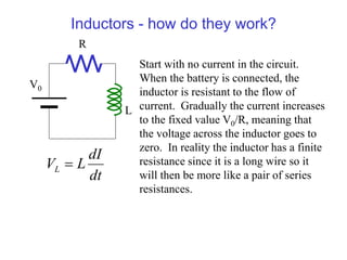
1) An inductor resists changes in current and has an impedance of iωL.
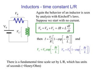
2) In an RLC circuit, the behavior is determined by the time constant L/R. If L/R is small, the circuit is overdamped; if L/R is large, it is underdamped and will ring.
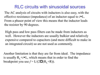
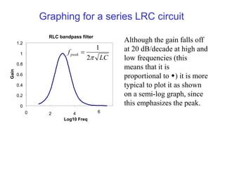
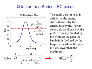
3) An RLC circuit can act as a bandpass filter, with peak gain occurring at the resonant frequency of 1/√LC. The quality factor Q relates to the bandwidth around the peak gain.


![Lecture-6-[Passive Filter].pdfmmmmmmmmmmmmmmmmmmmm](https://cdn.slidesharecdn.com/ss_thumbnails/lecture-6-passivefilter-251130051517-4644d20e-thumbnail.jpg?width=640&height=640&fit=bounds)


