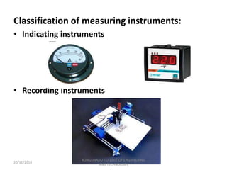
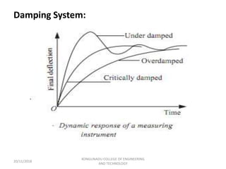
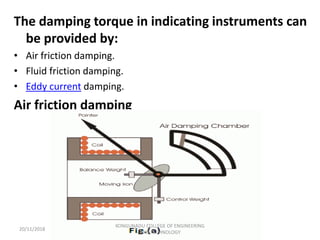
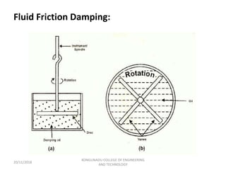
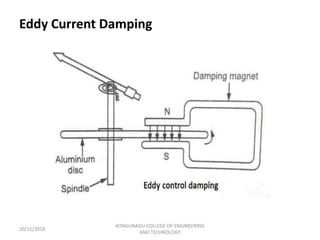
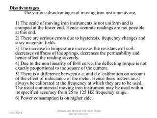
The document discusses various types of electrical measuring instruments. It describes indicating instruments which have a moving pointer system to directly indicate the measured quantity. The essential components of indicating instruments are the deflecting, controlling, and damping systems. Permanent magnet moving coil instruments are discussed as the most accurate for DC measurements. Moving iron instruments that can be used for both AC and DC are also summarized, including attraction and repulsion types. Sources of error in various instruments are outlined.


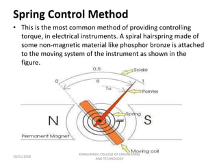
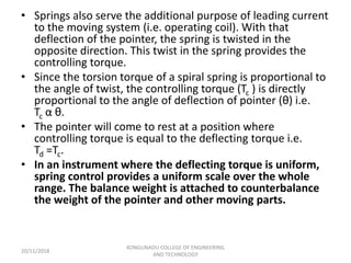
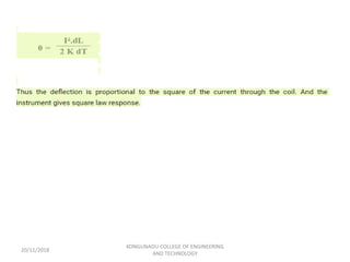


![ELECTRICAL MEASUREMENT & MEASURING INSTRUMENTS [Emmi- (NEE-302) -unit-1]](https://cdn.slidesharecdn.com/ss_thumbnails/emmi-nee-302-unit-1-170607090405-thumbnail.jpg?width=640&height=640&fit=bounds)