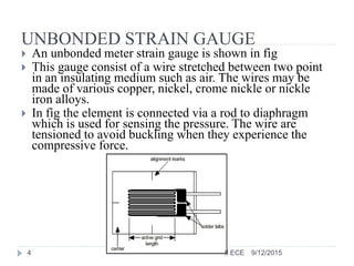
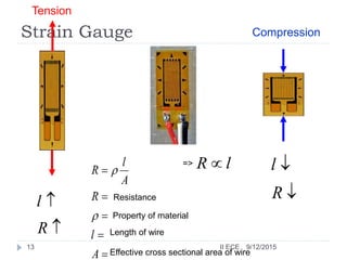
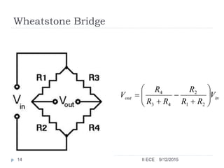
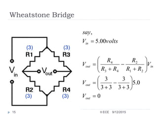
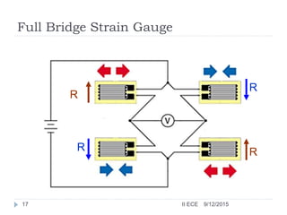
PRESSURE MEASUREMENT
STRAIN GAUGE
9/12/20151 II ECE
STRAIN GAUGE
 The strain gauge is a passive, resistive transducer which
converts the mechanical elongation and compression into a
resistance change.
 This change in resistance takes place due to variation in length
and cross sectional area of the gauge wire, when an external
force acts on it.
9/12/20152 II ECE
TYPES OF STRAIN GAUGE
• The type of strain gauge are as
a) Unbonded
b) Bonded
9/12/20153 II ECE
UNBONDED STRAIN GAUGE
 An unbonded meter strain gauge is shown in fig
 This gauge consist of a wire stretched between two point
in an insulating medium such as air. The wires may be
made of various copper, nickel, crome nickle or nickle
iron alloys.
 In fig the element is connected via a rod to diaphragm
which is used for sensing the pressure. The wire are
tensioned to avoid buckling when they experience the
compressive force.
9/12/20154 II ECE
 The unbounded meter wire gauges used almost exclusively in
transducer application employ preloaded resistance wire
connected in Wheatstone bridge as shown in fig.
 At initial preload the strain and resistance of the four arms are
nominally equal with the result the output voltage of the bridge
is equal to zero.
 Application of pressure produces a small displacement , the
displacement increases a tension in two wire and decreases it in
the other two thereby increase the resistance of two wire which
are in tension and decreasing the resistance of the remaining
two wire .
 This causes an unbalance of the bridge producing an output
voltage which is proportional to the input displacement and
hence to the applied pressure .
9/12/20155 II ECE
BONDED STRAIN GAUGE
 The bonded metal wire strain gauge are used for both
stress analysis and for construction of transducer.
 A resistance wire strain gauge consist of a grid of fine
resistance wire. The grid is cemented to carrier which
may be a thin sheet of paper bakelite or teflon.
 The wire is covered on top with a thin sheet of
material so as to prevent it from any mechanical
damage.
 The carrier is bonded with an adhesive material to the
specimen which permit a good transfer of strain from
carrier to grid of wires.
9/12/20156 II ECE
BONDED METAL FOIL STRAIN GAUGE
 It consist of following parts:
1. Base (carrier) Materials: several types of base material are
used to support the wires. Impregnated paper is used for room
temp. applications.
2. Adhesive: The adhesive acts as bonding materials. Like other
bonding operation, successful strain gauge bonding depends
upon careful surface preparation and use of the correct bonding
agent.
In order that the strain be faithfully transferred on to the
strain gauge, the bond has to be formed between the surface to
be strained and the plastic backing material on which the gauge
is mounted .
.
9/12/20157 II ECE
9/12/20158 II ECE
It is important that the adhesive should be suited to
this backing and adhesive material should be quick
drying type and also insensitive to moisture.
3. Leads: The leads should be of such materials which
have low and stable resistivity and also a low
resistance temperature coefficient
9/12/20159 II ECE
Strain Gauge Transducers(cont’d)
Where
 = the specific resistance of the conductor material
in ohm
 L = the length of the conductor in meters
 A = the area of the conductor in square meters
A
L
R



9/12/201510 II ECE
Strain Gauge Transducers(cont’d)
 As a consequence of strain two physical qualities are of particular
interest: (1) the change in gauge resistance and (2) the change in
length. The relationship between these two variables expressed as
a ratio is called the gauge factor.
 GF. Expressed mathematically as
(2)
Where
 GF = the gauge factor
 R = the initial resistance in ohms (without strain)
 = the change in initial resistance in ohms
 L = the initial length in meters (without strain)
 = the change in initial length in meters
LL
RR
GF
/
/



L
R
9/12/201511 II ECE
Strain Gauge Transducers(cont’d)
 Stress is defined as the internal force per unit area. The stress
equation is
(4)
Where
 S = the stress in kilograms per Square meter
 F = the force in kilograms
 A = the area in square meters
A
F
S 
9/12/201512 II ECE
Strain Gauge
Resistance





A
l
R
A
l
R


Property of material
Length of wire
Effective cross sectional area of wire
lR 


R
l


R
l
=>
Tension
Compression
9/12/201513 II ECE
Wheatstone Bridge
inout V
RR
R
RR
R
V 









21
2
43
4
9/12/201514 II ECE
Wheatstone Bridge
(3)(3)
(3)(3) 0
0.5
33
3
33
3
00.5
,
21
2
43
4






















out
out
inout
in
V
V
V
RR
R
RR
R
V
voltsV
say
9/12/201515 II ECE
Wheatstone Bridge
(2)(4)
(4)(2)
voltsV
V
V
V
RR
R
RR
R
V
voltsV
say
out
out
out
inout
in
667.1
0.5
6
2
6
4
0.5
24
2
42
4
00.5
,
21
2
43
4





























9/12/201516 II ECE
Full Bridge Strain Gauge
R
R
R R
9/12/201517 II ECE
Tension
Compression
No Force Applied
R
R
R
R
9/12/201518 II ECE
Bending Beam Load Cell
Strain Gauge
Strain Gauge
9/12/201519 II ECE
Bending Beam Load Cell
Strain Gauge
In Tension
Strain Gauge
in compression
9/12/201520 II ECE
THANK YOU
9/12/201521 II ECE

Strain gauge

  • 1.
  • 2.
    STRAIN GAUGE  Thestrain gauge is a passive, resistive transducer which converts the mechanical elongation and compression into a resistance change.  This change in resistance takes place due to variation in length and cross sectional area of the gauge wire, when an external force acts on it. 9/12/20152 II ECE
  • 3.
    TYPES OF STRAINGAUGE • The type of strain gauge are as a) Unbonded b) Bonded 9/12/20153 II ECE
  • 4.
    UNBONDED STRAIN GAUGE An unbonded meter strain gauge is shown in fig  This gauge consist of a wire stretched between two point in an insulating medium such as air. The wires may be made of various copper, nickel, crome nickle or nickle iron alloys.  In fig the element is connected via a rod to diaphragm which is used for sensing the pressure. The wire are tensioned to avoid buckling when they experience the compressive force. 9/12/20154 II ECE
  • 5.
     The unboundedmeter wire gauges used almost exclusively in transducer application employ preloaded resistance wire connected in Wheatstone bridge as shown in fig.  At initial preload the strain and resistance of the four arms are nominally equal with the result the output voltage of the bridge is equal to zero.  Application of pressure produces a small displacement , the displacement increases a tension in two wire and decreases it in the other two thereby increase the resistance of two wire which are in tension and decreasing the resistance of the remaining two wire .  This causes an unbalance of the bridge producing an output voltage which is proportional to the input displacement and hence to the applied pressure . 9/12/20155 II ECE
  • 6.
    BONDED STRAIN GAUGE The bonded metal wire strain gauge are used for both stress analysis and for construction of transducer.  A resistance wire strain gauge consist of a grid of fine resistance wire. The grid is cemented to carrier which may be a thin sheet of paper bakelite or teflon.  The wire is covered on top with a thin sheet of material so as to prevent it from any mechanical damage.  The carrier is bonded with an adhesive material to the specimen which permit a good transfer of strain from carrier to grid of wires. 9/12/20156 II ECE
  • 7.
    BONDED METAL FOILSTRAIN GAUGE  It consist of following parts: 1. Base (carrier) Materials: several types of base material are used to support the wires. Impregnated paper is used for room temp. applications. 2. Adhesive: The adhesive acts as bonding materials. Like other bonding operation, successful strain gauge bonding depends upon careful surface preparation and use of the correct bonding agent. In order that the strain be faithfully transferred on to the strain gauge, the bond has to be formed between the surface to be strained and the plastic backing material on which the gauge is mounted . . 9/12/20157 II ECE
  • 8.
  • 9.
    It is importantthat the adhesive should be suited to this backing and adhesive material should be quick drying type and also insensitive to moisture. 3. Leads: The leads should be of such materials which have low and stable resistivity and also a low resistance temperature coefficient 9/12/20159 II ECE
  • 10.
    Strain Gauge Transducers(cont’d) Where = the specific resistance of the conductor material in ohm  L = the length of the conductor in meters  A = the area of the conductor in square meters A L R    9/12/201510 II ECE
  • 11.
    Strain Gauge Transducers(cont’d) As a consequence of strain two physical qualities are of particular interest: (1) the change in gauge resistance and (2) the change in length. The relationship between these two variables expressed as a ratio is called the gauge factor.  GF. Expressed mathematically as (2) Where  GF = the gauge factor  R = the initial resistance in ohms (without strain)  = the change in initial resistance in ohms  L = the initial length in meters (without strain)  = the change in initial length in meters LL RR GF / /    L R 9/12/201511 II ECE
  • 12.
    Strain Gauge Transducers(cont’d) Stress is defined as the internal force per unit area. The stress equation is (4) Where  S = the stress in kilograms per Square meter  F = the force in kilograms  A = the area in square meters A F S  9/12/201512 II ECE
  • 13.
    Strain Gauge Resistance      A l R A l R   Property ofmaterial Length of wire Effective cross sectional area of wire lR    R l   R l => Tension Compression 9/12/201513 II ECE
  • 14.
    Wheatstone Bridge inout V RR R RR R V          21 2 43 4 9/12/201514 II ECE
  • 15.
  • 16.
  • 17.
    Full Bridge StrainGauge R R R R 9/12/201517 II ECE
  • 18.
  • 19.
    Bending Beam LoadCell Strain Gauge Strain Gauge 9/12/201519 II ECE
  • 20.
    Bending Beam LoadCell Strain Gauge In Tension Strain Gauge in compression 9/12/201520 II ECE
  • 21.