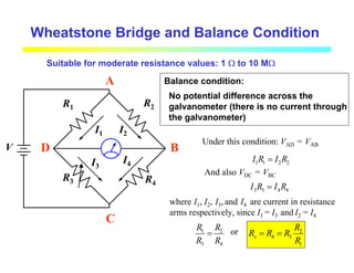
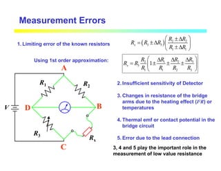
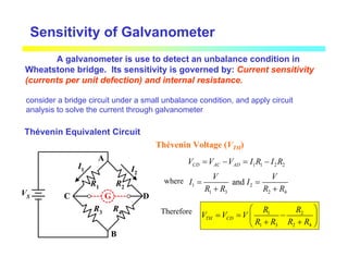
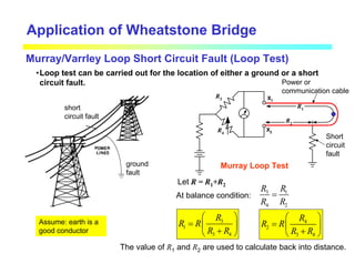
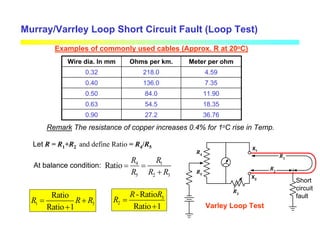
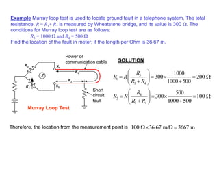
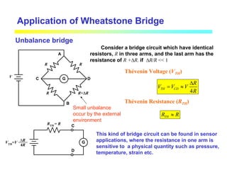
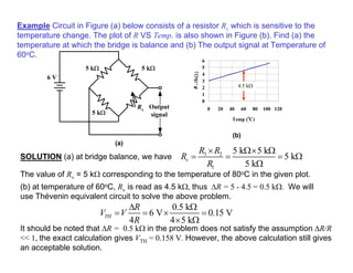
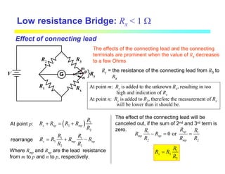
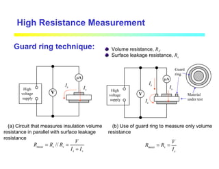
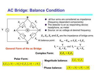
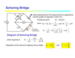
The document describes various electrical measurement and instrumentation techniques. It discusses bridge circuits including Wheatstone bridges, which can be used to measure resistance. It also describes other instruments such as voltmeter-ammeter methods, substitution techniques using decade boxes, and ohmmeters. Sources of error in measurements are outlined. Applications of Wheatstone bridges include locating faults in power cables using loop testing methods.
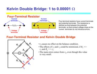
![Kelvin Double Bridge: 1 to 0.00001 Ω
G
R3
R1
R2
Rx
p
m
n
Ry
o
k
l
V
I
Rb
Ra
2 ratio arms: R1-R2 and Ra-Rb
the connecting lead between m and n: yoke
The balance conditions: Vlk = Vlmp or Vok = Vonp
2
1 2
lk
R
V V
R R
=
+
here 3
[ ( ) // ]
lo x a b y
V IR I R R R R R
= = + + +
3
y
lmp b
a b y
R
V I R R
R R R
= +
+ +
(1)
(2)
Eq. (1) = (2) and rearrange: 1 1
3
2 2
b y a
x
a b y b
R R R
R R
R R
R R R R R R
= + −
+ +
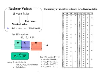
If we set R1/R2 = Ra/Rb, the second term of the right hand side will be zero, the relation
reduce to the well known relation. In summary, The resistance of the yoke has no effect
on the measurement, if the two sets of ratio arms have equal resistance ratios.
1
3
2
x
R
R R
R
=](https://image.slidesharecdn.com/2102311electricalmeasurementandinstr-240321133241-372237cd/85/2102311_Electrical_Measurement_and_Instr-pdf-25-320.jpg)


![Tema 8. sistemas_trifasicos[1]](https://cdn.slidesharecdn.com/ss_thumbnails/tema8-140205105719-phpapp01-thumbnail.jpg?width=640&height=640&fit=bounds)


