The document describes two types of wattmeters:
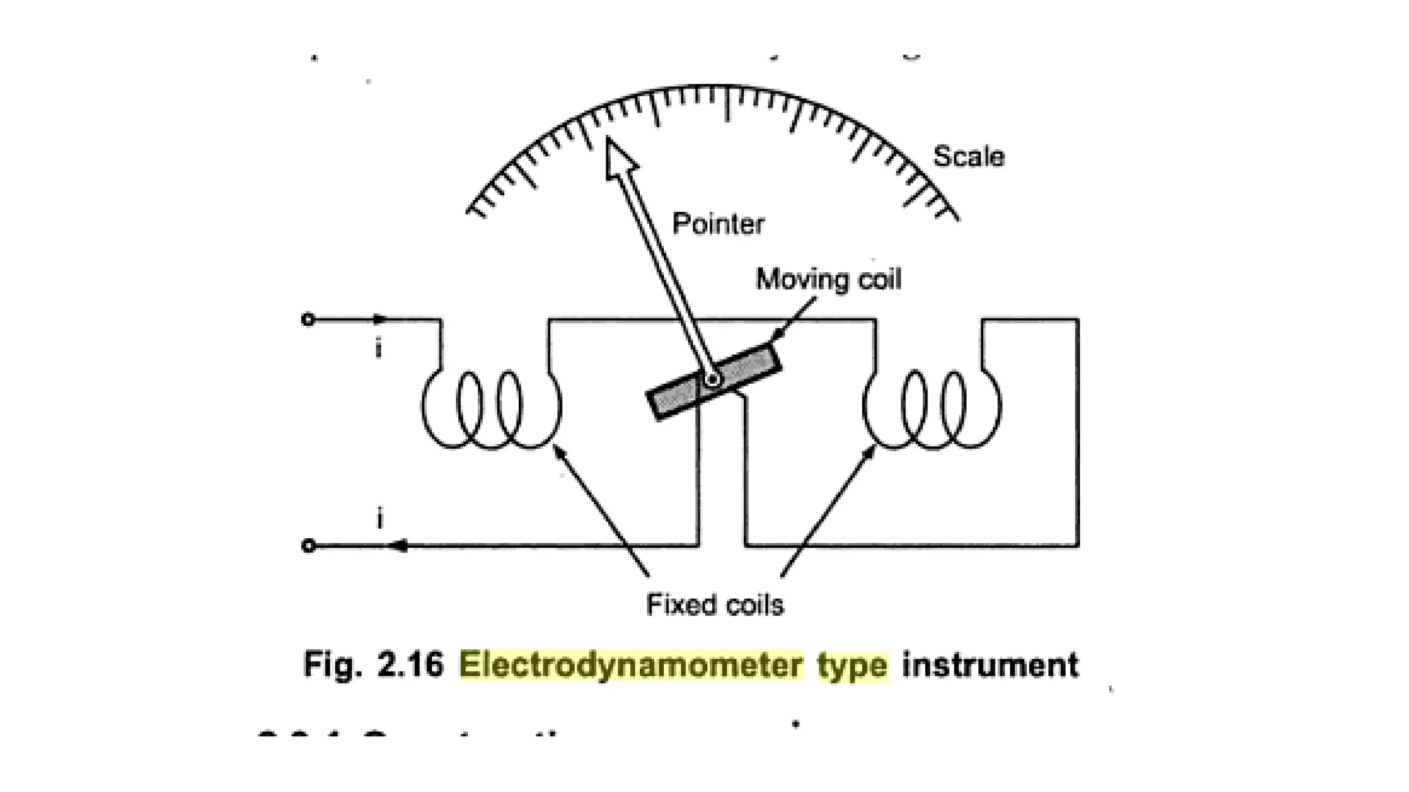
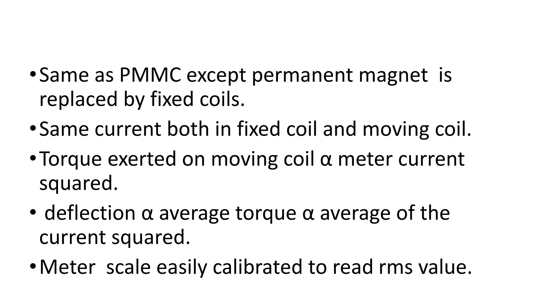
(1) Dynamometer type wattmeter which measures power using a moving coil placed in a magnetic field produced by a fixed coil. Deflection of the moving coil is proportional to the square of the current.
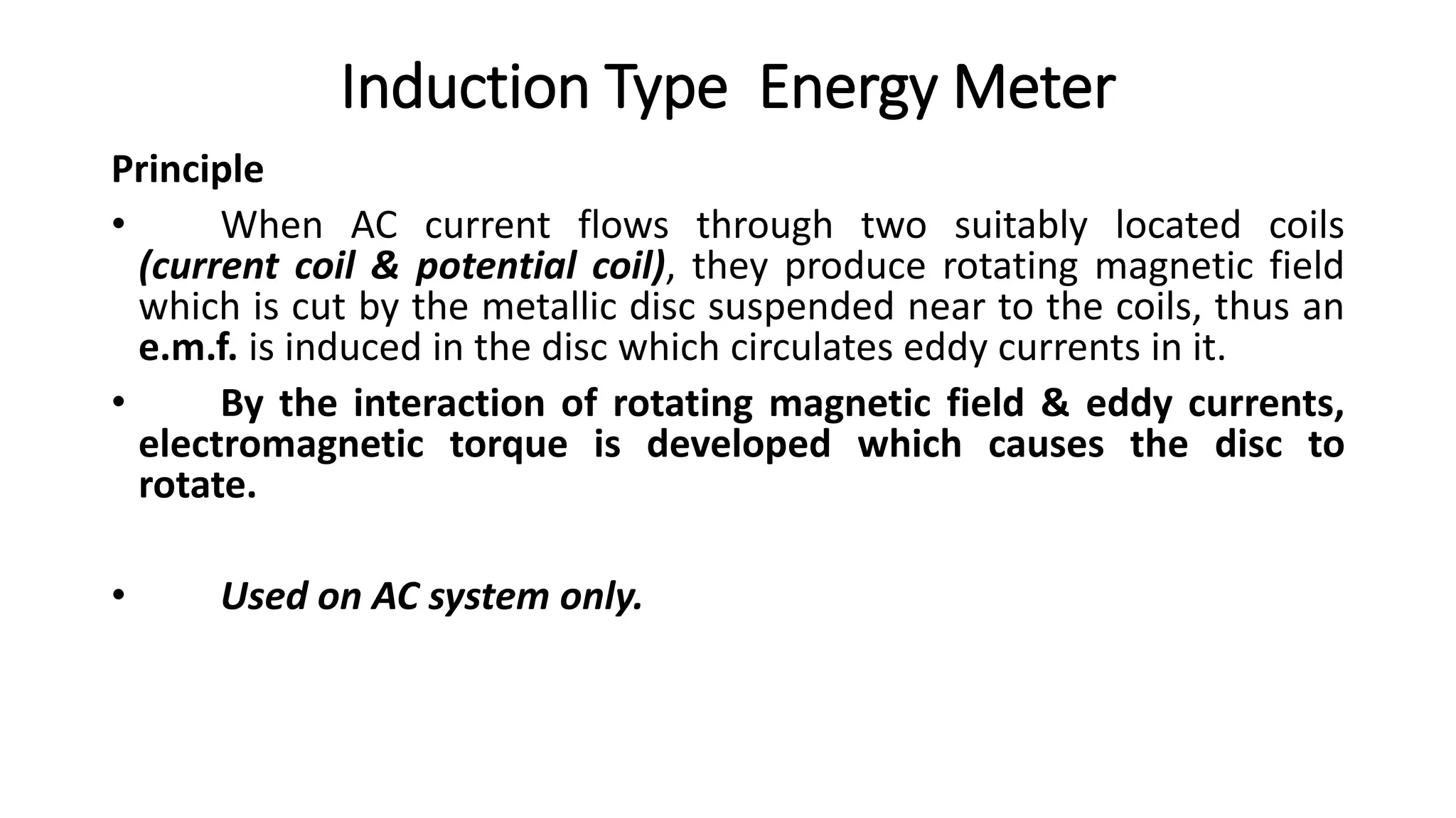
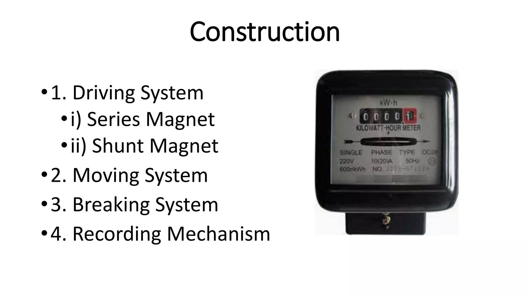
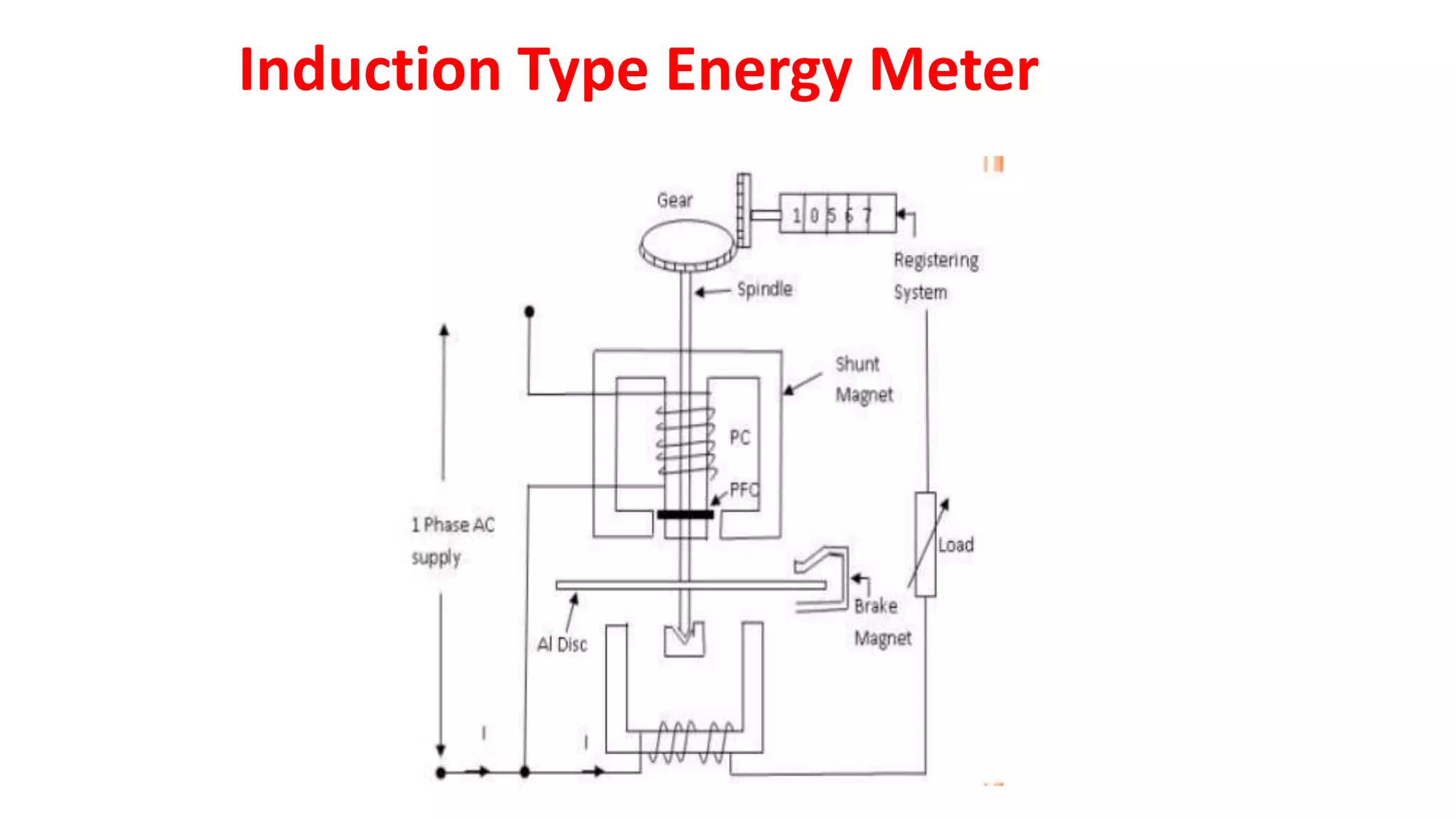
(2) Induction type energy meter which uses a rotating magnetic field produced by current and potential coils cutting a metallic disc to induce eddy currents and rotate the disc. The number of disc revolutions is registered to indicate energy consumed. It is used on AC systems only.