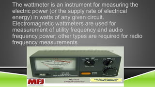
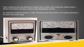
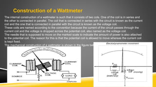
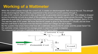
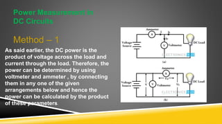
INTRODUCTION TO
WATTMETER & ITS
ESSENTIALS
Presented by : Muhammad Farhan
Roll Number : K-15EL01
The wattmeter is an instrument for measuring the
electric power (or the supply rate of electrical
energy) in watts of any given circuit.
Electromagnetic wattmeters are used for
measurement of utility frequency and audio
frequency power; other types are required for radio
frequency measurements.
Power is defined as the work performed in a specific time or simply a rate of doing work. Electric power is
defined as the electric work done or electric energy dissipated per unit time.
It is measured in Joules per second, i.e., watts. The power can be a DC quantity or AC quantity depending on
the nature of the power supply.
CLASSIFIED HISTORICAL BACKGROUND
 In 1881 The Fort Wayne Electric Light Co. was incorporated to sell a dynamo and arc
lamps patented by James Jenney. Ronald T. McDonald was the founder and president of
this company.
 In 1885 Galileo Ferraris of Turin, Italy makes a key discovery that two out of phase AC
fields can make a solid armature rotate
 In 1889 Thomson introduced his recording wattmeter. This was the first true watthour
meter, and it was an immediate commercial success, many utilities adopting it as their
"standard" model. Although this meter was initially designed for use on AC circuits, it
worked equally well with the DC circuits in use at the time. The introduction and rapid
acceptance of induction-type watthour meters in the late 1890s relegated the use of this
commutator-type meter to DC circuits.
 In 1898 Duncan develops a watthour meter for Fort Wayne Electric Corp. This meter
resembled GE's Thomson Recording Wattmeter except that it was an induction type with
a cup-shaped rotor.
HOW DOES A WATTMETER WORK?
Construction of a Wattmeter
The internal construction of a wattmeter is such that it consists of two cols. One of the coil is in series and
the other is connected in parallel. The coil that is connected in series with the circuit is known as the current
coil and the one that is connected in parallel with the circuit is known as the voltage coil.
These coils are named according to the convention because the current of the circuit passes through the
current coil and the voltage is dropped across the potential coil, also named as the voltage coil.
The needle that is supposed to move on the marked scale to indicate the amount of power is also attached
to the potential coil. The reason for this is that the potential coil is allowed to move whereas the current coil
is kept fixed.
The mechanical construction of a wattmeter is shown in the figure below.
Working of a Wattmeter
When the current passes through the current coil, it creates an electromagnetic field around the coil. The strength
of this electromagnetic field is directly proportional to the amount of current passing through it.
In case of DC current, the current is also in phase with its generated electromagnetic field. The voltage is dropped
across the potential coil and as a result of this complete process, the needle moves across the scale. The needle
deflection is such that it is according to the product of the current passing and the voltage dropped, that is, P = VI.
This was the case of DC power. We know that the AC power is given by the formula P = VIcosθ, and we know
that this cosθ factor is because of the fact that the current and voltage are not in phase.
But the question that arises here is that how will a wattmeter measure the AC power and this power factor? So
the wattmeter simply measures the average power in case if AC power is required.
The measurement principle of wattmeter is shown in the figure below:
Power Measurement in
DC Circuits
Method – 1
As said earlier, the DC power is the
product of voltage across the load and
current through the load. Therefore, the
power can be determined by using
voltmeter and ammeter , by connecting
them in any one of the given
arrangements below and hence the
power can be calculated by the product
of these parameters.
n figure (a), the ammeter measures the total current through the circuit and this current
is the sum of current through the load and current through voltmeter. So the
measurement of power includes the power absorption by the meter.
This is avoided in arrangement (b), but the voltmeter measures the voltage drop across
the ammeter in addition to voltage across the load and hence the error in the
measurement. These errors are called as insertion errors.
However, these errors can be neglected when Iv is compared with I and Va compared
with V. so the measured power will coincide with true power.
Since the voltmeter and ammeter are more sensitive than a wattmeter, the measured
value is more accurate than that obtained by a wattmeter. Therefore, power can be
calculated by the reading obtained by the meters.
P = V × I watts
Method – 2
The above method needs two measuring devices and also
requires some calculations. It is also possible to measure the
power directly by a single meter, called wattmeter. It is an
electrodynamic instrument consisting of a pair of fixed coils and
a moving coil.
Power Measurement in AC Circuits
Most of the AC power measurements rated at frequencies below 400 Hz are carried out
using dynamo meter type wattmeter. This measuring instrument indicates directly the
average power dissipated by the load.
Only one wattmeter is used in case of single phase power measurement while two
wattmeters are needed to measure the three phase power. In case unavailability of
wattmeters or incorrect measurements by a wattmeter, other methods are used.
Power Measurement in Single phase AC Circuits
Three voltmeter method
Three ammeter method
Wattmeter method
THREE VOLTMETER METHOD
THREE AMMETER METHOD
WATT METER METHOD
POWER MEASUREMENTS IN THREE PHASE AC
CIRCUITS
Three wattmeters method
Two wattmeters method
One wattmeter method
THREE WATTMETER METHOD
Star connected Delta connected
Two wattmeter method
Applications of Wattmeter
1.As other measuring instruments, watt meters are also used
extensively in electrical circuit measurement and debugging.
2.They are also used in industries to check the power rating and
consumption of electrical appliances.
3.Electromagnetic watt meters are used to measure utility
frequencies.
4.They are used with refrigerators, electric heaters and other
equipment to measure their power ratings.
Wattmeter Presentation

Wattmeter Presentation

  • 2.
    INTRODUCTION TO WATTMETER &ITS ESSENTIALS Presented by : Muhammad Farhan Roll Number : K-15EL01
  • 3.
    The wattmeter isan instrument for measuring the electric power (or the supply rate of electrical energy) in watts of any given circuit. Electromagnetic wattmeters are used for measurement of utility frequency and audio frequency power; other types are required for radio frequency measurements.
  • 4.
    Power is definedas the work performed in a specific time or simply a rate of doing work. Electric power is defined as the electric work done or electric energy dissipated per unit time. It is measured in Joules per second, i.e., watts. The power can be a DC quantity or AC quantity depending on the nature of the power supply.
  • 9.
    CLASSIFIED HISTORICAL BACKGROUND In 1881 The Fort Wayne Electric Light Co. was incorporated to sell a dynamo and arc lamps patented by James Jenney. Ronald T. McDonald was the founder and president of this company.  In 1885 Galileo Ferraris of Turin, Italy makes a key discovery that two out of phase AC fields can make a solid armature rotate  In 1889 Thomson introduced his recording wattmeter. This was the first true watthour meter, and it was an immediate commercial success, many utilities adopting it as their "standard" model. Although this meter was initially designed for use on AC circuits, it worked equally well with the DC circuits in use at the time. The introduction and rapid acceptance of induction-type watthour meters in the late 1890s relegated the use of this commutator-type meter to DC circuits.  In 1898 Duncan develops a watthour meter for Fort Wayne Electric Corp. This meter resembled GE's Thomson Recording Wattmeter except that it was an induction type with a cup-shaped rotor.
  • 10.
    HOW DOES AWATTMETER WORK?
  • 11.
    Construction of aWattmeter The internal construction of a wattmeter is such that it consists of two cols. One of the coil is in series and the other is connected in parallel. The coil that is connected in series with the circuit is known as the current coil and the one that is connected in parallel with the circuit is known as the voltage coil. These coils are named according to the convention because the current of the circuit passes through the current coil and the voltage is dropped across the potential coil, also named as the voltage coil. The needle that is supposed to move on the marked scale to indicate the amount of power is also attached to the potential coil. The reason for this is that the potential coil is allowed to move whereas the current coil is kept fixed. The mechanical construction of a wattmeter is shown in the figure below.
  • 12.
    Working of aWattmeter When the current passes through the current coil, it creates an electromagnetic field around the coil. The strength of this electromagnetic field is directly proportional to the amount of current passing through it. In case of DC current, the current is also in phase with its generated electromagnetic field. The voltage is dropped across the potential coil and as a result of this complete process, the needle moves across the scale. The needle deflection is such that it is according to the product of the current passing and the voltage dropped, that is, P = VI. This was the case of DC power. We know that the AC power is given by the formula P = VIcosθ, and we know that this cosθ factor is because of the fact that the current and voltage are not in phase. But the question that arises here is that how will a wattmeter measure the AC power and this power factor? So the wattmeter simply measures the average power in case if AC power is required. The measurement principle of wattmeter is shown in the figure below:
  • 13.
    Power Measurement in DCCircuits Method – 1 As said earlier, the DC power is the product of voltage across the load and current through the load. Therefore, the power can be determined by using voltmeter and ammeter , by connecting them in any one of the given arrangements below and hence the power can be calculated by the product of these parameters.
  • 14.
    n figure (a),the ammeter measures the total current through the circuit and this current is the sum of current through the load and current through voltmeter. So the measurement of power includes the power absorption by the meter. This is avoided in arrangement (b), but the voltmeter measures the voltage drop across the ammeter in addition to voltage across the load and hence the error in the measurement. These errors are called as insertion errors. However, these errors can be neglected when Iv is compared with I and Va compared with V. so the measured power will coincide with true power. Since the voltmeter and ammeter are more sensitive than a wattmeter, the measured value is more accurate than that obtained by a wattmeter. Therefore, power can be calculated by the reading obtained by the meters. P = V × I watts
  • 15.
    Method – 2 Theabove method needs two measuring devices and also requires some calculations. It is also possible to measure the power directly by a single meter, called wattmeter. It is an electrodynamic instrument consisting of a pair of fixed coils and a moving coil.
  • 16.
    Power Measurement inAC Circuits Most of the AC power measurements rated at frequencies below 400 Hz are carried out using dynamo meter type wattmeter. This measuring instrument indicates directly the average power dissipated by the load. Only one wattmeter is used in case of single phase power measurement while two wattmeters are needed to measure the three phase power. In case unavailability of wattmeters or incorrect measurements by a wattmeter, other methods are used. Power Measurement in Single phase AC Circuits Three voltmeter method Three ammeter method Wattmeter method
  • 17.
  • 18.
  • 19.
  • 20.
    POWER MEASUREMENTS INTHREE PHASE AC CIRCUITS Three wattmeters method Two wattmeters method One wattmeter method
  • 21.
    THREE WATTMETER METHOD Starconnected Delta connected
  • 22.
  • 23.
    Applications of Wattmeter 1.Asother measuring instruments, watt meters are also used extensively in electrical circuit measurement and debugging. 2.They are also used in industries to check the power rating and consumption of electrical appliances. 3.Electromagnetic watt meters are used to measure utility frequencies. 4.They are used with refrigerators, electric heaters and other equipment to measure their power ratings.