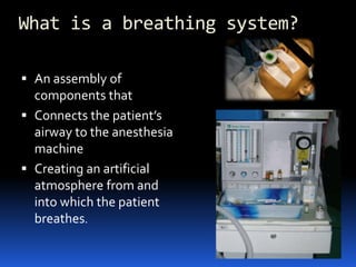
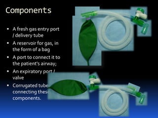
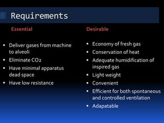
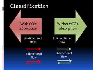
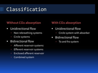
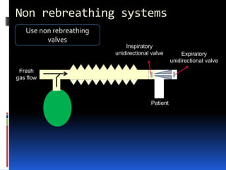
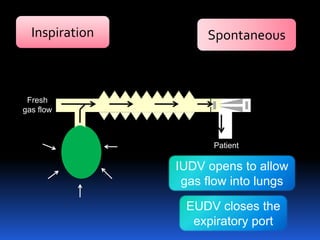
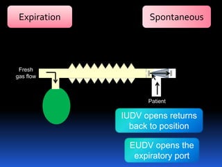
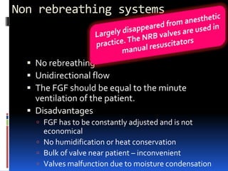
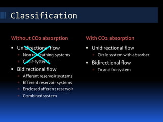
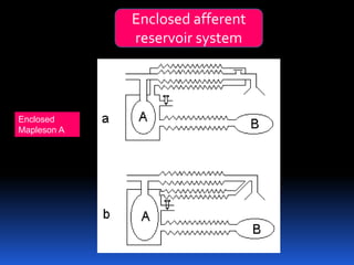
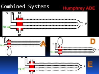
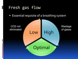
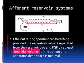
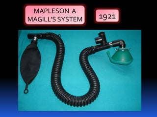
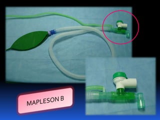
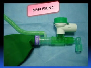
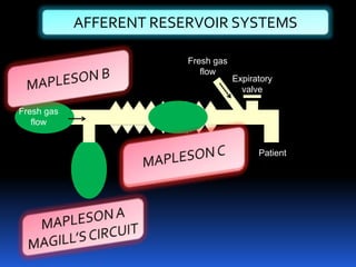
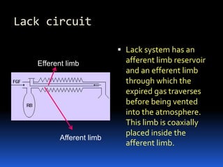
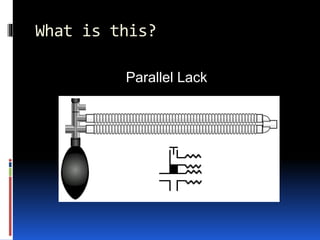
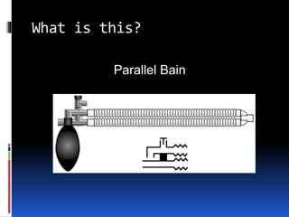
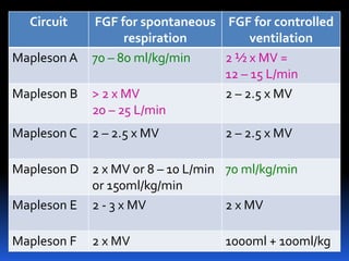
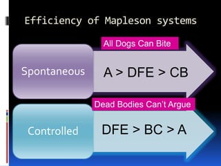
DR BRIJESH SAVIDHAN
DEPT OF ANAESTHESIOLOGY
TRAVANCORE MEDICAL COLLEGE
BREATHING SYSTEMS
What is a breathing system?
 An assembly of
components that
 Connects the patient’s
airway to the anesthesia
machine
 Creating an artificial
atmosphere from and
into which the patient
breathes.
Components
 A fresh gas entry port
/ delivery tube
 A reservoir for gas, in
the form of a bag
 A port to connect it to
the patient's airway;
 An expiratory port /
valve
 Corrugated tubes for
connecting these
components.
Components
 A CO2 absorber if total rebreathing is to be allowed
 Flow directing valves may or may not be present
 Connectors and adapters
 Filters
Requirements
Essential Desirable
 Deliver gases from machine
to alveoli
 Eliminate CO2
 Have minimal apparatus
dead space
 Have low resistance
 Economy of fresh gas
 Conservation of heat
 Adequate humidification of
inspired gas
 Light weight
 Convenient
 Efficient for both spontaneous
and controlled ventilation
 Adapatable
Classification
With CO2
absorption
Without CO2
absorption
Unidirectional
flow
Unidirectional
flow
Bidirectional
flow
Bidirectional
flow
Classification
Without CO2 absorption With CO2 absorption
 Unidirectional flow
 Non rebreathing systems
 Circle systems
 Bidirectional flow
 Afferent reservoir systems
 Efferent reservoir systems
 Enclosed afferent reservoir
 Combined system
 Unidirectional flow
 Circle system with absorber
 Bidirectional flow
 To and fro system
Expiratory
unidirectional valve
Inspiratory
unidirectional valve
Non rebreathing systems
Use non rebreathing
valves
Patient
Fresh
gas flow
Inspiration Spontaneous
EUDV closes the
expiratory port
IUDV opens to allow
gas flow into lungs
Fresh
gas flow
Patient
Expiration Spontaneous
IUDV opens returns
back to position
EUDV opens the
expiratory port
Fresh
gas flow
Patient
Non rebreathing systems
 No rebreathing
 Unidirectional flow
 The FGF should be equal to the minute
ventilation of the patient.
 Disadvantages
 FGF has to be constantly adjusted and is not
economical
 No humidification or heat conservation
 Bulk of valve near patient – inconvenient
 Valves malfunction due to moisture condensation
Classification
Without CO2 absorption With CO2 absorption
 Unidirectional flow
 Non rebreathing systems
 Circle systems
 Bidirectional flow
 Afferent reservoir systems
 Efferent reservoir systems
 Enclosed afferent reservoir
 Combined system
 Unidirectional flow
 Circle system with absorber
 Bidirectional flow
 To and fro system
Afferent
reservoir
Efferent
reservoir
Enclosed
afferent
reservoir
Combined
Bi
directional
flow
Afferent Reservoir Systems
 The afferent limb is that part of the breathing
system which delivers the FG from the machine to
the pt. If the reservoir is placed in this limb, they are
called afferent reservoir systems.
 Mapleson A, B, C
Efferent reservoir systems
 The efferent limb is that part of the breathing
system which carries expired gas from the patient
and vents it to the atmosphere through the
expiratory valve/port. If the reservoir is placed in
this limb, they are called efferent reservoir systems
 Mapleson D, E, F
v
FGF
from
machine v
FGF
from
machine
Reservoir is in
the afferent limb
Reservoir is in
the efferent limb
Efferent limb
Afferent limb ARS
ERS
Patient
Patient
Enclosed afferent
reservoir system
Enclosed
Mapleson A
Humphrey ADECombined Systems
Bidirectional flow
 Depend on FGF for effective elimination of CO2
 Can be manipulated by changing parameters
 Fresh gas flow
 Alveolar ventilation
 Apparatus dead space
Fresh gas flow
 It is imperative to specify optimum FGF for a
breathing system for efficient functioning.
 FGF should be delivered as near the patient’s
airway as possible.
Fresh gas flow
 Essential requisite of a breathing system
High
Optimal
Low
CO2 not
eliminated
Wastage
of gases
Apparatus dead space
 Part of the breathing system from which exhaled
alveolar gases are rebreathed without any
significant change in their CO2 concentration
 Volume of the breathing system from the patient
end to the point upto which to and fro
movement of expired gas takes place.
Afferent reservoir
system
Efferent reservoir
system
Circle system
FGF
Expiratory valve
Apparatus dead space
 Should be minimal - rebreathing of CO2 could result
in hypercapnia
 The dynamic dead space depends on FGF and
alveolar ventilation
 The dead space is minimal with optimal FGF
 If the FGF is reduced below the optimal level, the
dead space increases and
 The whole system will act as dead space if there is
no FGF
Afferent reservoir systems
 Efficient during spontaneous breathing
provided the expiratory valve is separated
from the reservoir bag and FGF by at least
one tidal volume of the patient and
apparatus dead space is minimal
one tidal volume
MAPLESON A
MAGILL’S SYSTEM 1921
v
AFFERENT RESERVOIR SYSTEMS
Patient
Fresh gas
flow
Fresh gas
flow
Expiratory
valve
Lack circuit
 Lack system has an
afferent limb reservoir
and an efferent limb
through which the
expired gas traverses
before being vented
into the atmosphere.
This limb is coaxially
placed inside the
afferent limb.
Efferent limb
Afferent limb
Mapleson’s analysis
1. Gases move enbloc. They maintain their identity as
fresh gas, dead space gas and alveolar gas- No mixing
of gases.
2. The reservoir bag continues to fill up, without offering
any resistance till it is full
3. The expiratory valve opens as soon as the reservoir
bag is full and the pressure inside the system goes
above atmospheric pressure.
4. The valve remains open throughout the expiratory
phase without offering any resistance to gas flow and
closes at the start of the next inspiration.
Functional analysis
 Mapleson ‘A’/Magill’s system:
Spontaneous breathing: system is filled with FG before connecting to
the pt.When the pt inspires, FG from the machine and the reservoir
bag flows to the pt- bag collapses . During exprn, the FG continues
to flow into the system and fill the reservoir bag.The expired gas,
initial part - dead space gas, pushes the FG from the corrugated
tube into the reservoir bag and collects inside the corrugated tube.
As soon as the reservoir bag is full, the expiratory valve opens and
the alveolar gas is vented into the atmosphere . During the
expiratory pause, alveolar gas that had come into the corrugated
tube is also pushed out through the valve, depending on the FGF.
The system is filled with only FG and dead space gas at the start of
the next insprn when FGF = alveolar ventilation .The entire alveolar
gas and dead space gas is vented through the valve and some FG
also escapes, if the FGF > MV. Some amt of alveolar gas will remain
in the system and lead to rebreathing with a FGF< MV. Max
efficiency, when the FGF = alveolar ventilation and the dead space
gas has is allowed to be rebreathed and utilized for alveolar
ventilation.
 Controlled ventilation: For IPPV the expiratory
valve - partly closed. During insprn, the pt gets
ventilated with FG and part of the FG is vented
through the valve after sufficient pressure has
developed to open the valve. During exprn, the FG
from the machine flows into the reservoir bag and
all the expired gas flows back into the corrugated
tube till the system is full . During next insprn the
alveolar gas is pushed back into the alveoli followed
by the FG.When sufficient pressure is developed,
part of the expired gas and part of the FG escape
through the valve. Considerable rebreathing,
excessive waste of FG.
To summarize afferent
reservoir systems.....
 Mapleson A is efficient only for spontaneous
respiration and is inefficient for controlled
ventilation
 Mapleson B and C are inefficient for both
spontaneous respiration and controlled
ventilation
Efferent reservoir systems
 Works efficiently and economically for
controlled ventilation as long as the FG entry
and the expiratory valve are separated by a
volume equivalent to atleast oneTV of the
patient
 Not economical during spontaneous
breathing
NO
RESERVOIR
BAG
Ayre's T-piece (1937)
 Light metal tube 1 cm
in diameter, 5 cm in
length with a side arm
 Used as such, it
functions as a non-
rebreathing system
 FGF equal to peak
inspiratory flow rate of
the patient
RESERVOIR
TUBE
TO PATIENT
FRESH GAS
FLOW
EFFERENT RESERVOIR SYSTEMS
Fresh gas
from machine
Patient
Expiratory
valve
Efferent
limb
EFFERENT RESERVOIR SYSTEMS
1972 Bain and
Spoerel
Patient
Afferent
limb
Efferent
limb
Machine end
Patient end
Bains circuit- spontaneous
 When pt inspires, the FG from the machine, the reservoir
bag and the corrugated tube flow to the pt . During exprn,
there is a continuous FGF into the system at the pt end.The
expired gas gets continuously mixed with the FG as it flows
back into the corrugated tube and the reservoir bag . Once
the system is full the excess gas is vented to the atmosphere
through the valve situated at the end of the corrugated tube
near the reservoir bag. During the expiratory pause the FG
continues to flow and fill the proximal portion of the
corrugated tube while the mixed gas is vented through the
valve . During the next inspiration, the patient breaths FG as
well as the mixed gas from the corrugated tube . Many
factors influence the composition of the inspired mixture.
They are FGF, respiratory rate, expiratory pause, tidal
volume and co2 production in the body. Factors other than
FGF cannot be manipulated in a spontaneously breathing
patient. FGF should be atleast 1.5 to 2 times the patient’s
minute ventilation to minimise rebreathing.
Bains -controlled
To facilitate IPPV, the expiratory valve has to be partly closed so that it
opens only after sufficient pressure has developed in the system.
When the system is filled with fresh gas, the patient gets ventilated
with the FGF from the machine, the corrugated tube and the
reservoir bag. During expiration, the expired gas continuously gets
mixed with the fresh gas that is flowing into the system at the
patient end. During the expiratory pause the FG continues to enter
the system and pushes the mixed gas towards the reservoir .When
the next inspiration is initiated, the patient gets ventilated with the
gas in the corrugated tube i.e., a mixture of FG, alveolar gas and
dead space gas . As the pressure in the system increases, the
expiratory valve opens and the contents of the reservoir bag are
discharged into the atmosphere. Factors that influence the
composition of gas mixture in the corrugated tube are FGF, RR,TV
and pattern of ventilation.These parameters can be totally
controlled by the anaesthesiologist and do not depend on the
patient. Using a low respiratory rate with a long expiratory pause
and a high tidal volume, most of the FG could be utilized for
alveolar ventilation without wastage.
Advantages of Bain’s
 Light weight
 Convenient
 Easily sterilized
 Scavenging facilitated as the expiratory valve being
located away from the patient
 Exhaled gases in the outer reservoir tubing add
warmth to the inspired fresh gases
Disadvantages
 Kinking, leakage and disconnections of inner
tube which can cause severe hypercapnia
 Outer tube should be transparent to allow
inspection of the inner tube
 Special tests
Test for Bain’s circuit
 Set a low flow of oxygen on the flowmeter
and occlude the inner tube .The indicator in
the flowmeter will fall slightly if the inner
tube is intact
 Pethick test
MaplesonAMapleson B
Mapleson C
Mapleson D
Mapleson E
Water’s canister
What is this?
Parallel Lack
What is this?
Parallel Bain
Circuit FGF for spontaneous
respiration
FGF for controlled
ventilation
Mapleson A 70 – 80 ml/kg/min 2 ½ x MV =
12 – 15 L/min
Mapleson B > 2 x MV
20 – 25 L/min
2 – 2.5 x MV
Mapleson C 2 – 2.5 x MV 2 – 2.5 x MV
Mapleson D 2 x MV or 8 – 10 L/min
or 150ml/kg/min
70 ml/kg/min
Mapleson E 2 - 3 x MV 2 x MV
Mapleson F 2 x MV 1000ml + 100ml/kg
Efficiency of Mapleson systems
Spontaneous
Controlled
A > DFE > CB
DFE > BC > A
All Dogs Can Bite
Dead Bodies Can’t Argue
Conclusion
 What is a breathing system?
 What are the components?
 What are the requisites?
 What is the classification?
 Can we identify the different circuits?
 Functional analysis of each
 Advantages and disadvantages of each.
Thank you

Breathing systems

  • 1.
    DR BRIJESH SAVIDHAN DEPTOF ANAESTHESIOLOGY TRAVANCORE MEDICAL COLLEGE BREATHING SYSTEMS
  • 2.
    What is abreathing system?  An assembly of components that  Connects the patient’s airway to the anesthesia machine  Creating an artificial atmosphere from and into which the patient breathes.
  • 3.
    Components  A freshgas entry port / delivery tube  A reservoir for gas, in the form of a bag  A port to connect it to the patient's airway;  An expiratory port / valve  Corrugated tubes for connecting these components.
  • 4.
    Components  A CO2absorber if total rebreathing is to be allowed  Flow directing valves may or may not be present  Connectors and adapters  Filters
  • 5.
    Requirements Essential Desirable  Delivergases from machine to alveoli  Eliminate CO2  Have minimal apparatus dead space  Have low resistance  Economy of fresh gas  Conservation of heat  Adequate humidification of inspired gas  Light weight  Convenient  Efficient for both spontaneous and controlled ventilation  Adapatable
  • 6.
  • 7.
    Classification Without CO2 absorptionWith CO2 absorption  Unidirectional flow  Non rebreathing systems  Circle systems  Bidirectional flow  Afferent reservoir systems  Efferent reservoir systems  Enclosed afferent reservoir  Combined system  Unidirectional flow  Circle system with absorber  Bidirectional flow  To and fro system
  • 8.
    Expiratory unidirectional valve Inspiratory unidirectional valve Nonrebreathing systems Use non rebreathing valves Patient Fresh gas flow
  • 9.
    Inspiration Spontaneous EUDV closesthe expiratory port IUDV opens to allow gas flow into lungs Fresh gas flow Patient
  • 10.
    Expiration Spontaneous IUDV opensreturns back to position EUDV opens the expiratory port Fresh gas flow Patient
  • 11.
    Non rebreathing systems No rebreathing  Unidirectional flow  The FGF should be equal to the minute ventilation of the patient.  Disadvantages  FGF has to be constantly adjusted and is not economical  No humidification or heat conservation  Bulk of valve near patient – inconvenient  Valves malfunction due to moisture condensation
  • 12.
    Classification Without CO2 absorptionWith CO2 absorption  Unidirectional flow  Non rebreathing systems  Circle systems  Bidirectional flow  Afferent reservoir systems  Efferent reservoir systems  Enclosed afferent reservoir  Combined system  Unidirectional flow  Circle system with absorber  Bidirectional flow  To and fro system
  • 13.
  • 14.
    Afferent Reservoir Systems The afferent limb is that part of the breathing system which delivers the FG from the machine to the pt. If the reservoir is placed in this limb, they are called afferent reservoir systems.  Mapleson A, B, C
  • 15.
    Efferent reservoir systems The efferent limb is that part of the breathing system which carries expired gas from the patient and vents it to the atmosphere through the expiratory valve/port. If the reservoir is placed in this limb, they are called efferent reservoir systems  Mapleson D, E, F
  • 16.
    v FGF from machine v FGF from machine Reservoir isin the afferent limb Reservoir is in the efferent limb Efferent limb Afferent limb ARS ERS Patient Patient
  • 17.
  • 18.
  • 19.
    Bidirectional flow  Dependon FGF for effective elimination of CO2  Can be manipulated by changing parameters  Fresh gas flow  Alveolar ventilation  Apparatus dead space
  • 20.
    Fresh gas flow It is imperative to specify optimum FGF for a breathing system for efficient functioning.  FGF should be delivered as near the patient’s airway as possible.
  • 21.
    Fresh gas flow Essential requisite of a breathing system High Optimal Low CO2 not eliminated Wastage of gases
  • 22.
    Apparatus dead space Part of the breathing system from which exhaled alveolar gases are rebreathed without any significant change in their CO2 concentration  Volume of the breathing system from the patient end to the point upto which to and fro movement of expired gas takes place.
  • 23.
  • 24.
    Apparatus dead space Should be minimal - rebreathing of CO2 could result in hypercapnia  The dynamic dead space depends on FGF and alveolar ventilation  The dead space is minimal with optimal FGF  If the FGF is reduced below the optimal level, the dead space increases and  The whole system will act as dead space if there is no FGF
  • 25.
    Afferent reservoir systems Efficient during spontaneous breathing provided the expiratory valve is separated from the reservoir bag and FGF by at least one tidal volume of the patient and apparatus dead space is minimal one tidal volume
  • 26.
  • 29.
    v AFFERENT RESERVOIR SYSTEMS Patient Freshgas flow Fresh gas flow Expiratory valve
  • 30.
    Lack circuit  Lacksystem has an afferent limb reservoir and an efferent limb through which the expired gas traverses before being vented into the atmosphere. This limb is coaxially placed inside the afferent limb. Efferent limb Afferent limb
  • 31.
    Mapleson’s analysis 1. Gasesmove enbloc. They maintain their identity as fresh gas, dead space gas and alveolar gas- No mixing of gases. 2. The reservoir bag continues to fill up, without offering any resistance till it is full 3. The expiratory valve opens as soon as the reservoir bag is full and the pressure inside the system goes above atmospheric pressure. 4. The valve remains open throughout the expiratory phase without offering any resistance to gas flow and closes at the start of the next inspiration.
  • 32.
    Functional analysis  Mapleson‘A’/Magill’s system: Spontaneous breathing: system is filled with FG before connecting to the pt.When the pt inspires, FG from the machine and the reservoir bag flows to the pt- bag collapses . During exprn, the FG continues to flow into the system and fill the reservoir bag.The expired gas, initial part - dead space gas, pushes the FG from the corrugated tube into the reservoir bag and collects inside the corrugated tube. As soon as the reservoir bag is full, the expiratory valve opens and the alveolar gas is vented into the atmosphere . During the expiratory pause, alveolar gas that had come into the corrugated tube is also pushed out through the valve, depending on the FGF. The system is filled with only FG and dead space gas at the start of the next insprn when FGF = alveolar ventilation .The entire alveolar gas and dead space gas is vented through the valve and some FG also escapes, if the FGF > MV. Some amt of alveolar gas will remain in the system and lead to rebreathing with a FGF< MV. Max efficiency, when the FGF = alveolar ventilation and the dead space gas has is allowed to be rebreathed and utilized for alveolar ventilation.
  • 34.
     Controlled ventilation:For IPPV the expiratory valve - partly closed. During insprn, the pt gets ventilated with FG and part of the FG is vented through the valve after sufficient pressure has developed to open the valve. During exprn, the FG from the machine flows into the reservoir bag and all the expired gas flows back into the corrugated tube till the system is full . During next insprn the alveolar gas is pushed back into the alveoli followed by the FG.When sufficient pressure is developed, part of the expired gas and part of the FG escape through the valve. Considerable rebreathing, excessive waste of FG.
  • 36.
    To summarize afferent reservoirsystems.....  Mapleson A is efficient only for spontaneous respiration and is inefficient for controlled ventilation  Mapleson B and C are inefficient for both spontaneous respiration and controlled ventilation
  • 37.
    Efferent reservoir systems Works efficiently and economically for controlled ventilation as long as the FG entry and the expiratory valve are separated by a volume equivalent to atleast oneTV of the patient  Not economical during spontaneous breathing
  • 38.
  • 40.
    Ayre's T-piece (1937) Light metal tube 1 cm in diameter, 5 cm in length with a side arm  Used as such, it functions as a non- rebreathing system  FGF equal to peak inspiratory flow rate of the patient RESERVOIR TUBE TO PATIENT FRESH GAS FLOW
  • 41.
    EFFERENT RESERVOIR SYSTEMS Freshgas from machine Patient Expiratory valve Efferent limb
  • 42.
    EFFERENT RESERVOIR SYSTEMS 1972Bain and Spoerel Patient Afferent limb Efferent limb
  • 43.
  • 44.
    Bains circuit- spontaneous When pt inspires, the FG from the machine, the reservoir bag and the corrugated tube flow to the pt . During exprn, there is a continuous FGF into the system at the pt end.The expired gas gets continuously mixed with the FG as it flows back into the corrugated tube and the reservoir bag . Once the system is full the excess gas is vented to the atmosphere through the valve situated at the end of the corrugated tube near the reservoir bag. During the expiratory pause the FG continues to flow and fill the proximal portion of the corrugated tube while the mixed gas is vented through the valve . During the next inspiration, the patient breaths FG as well as the mixed gas from the corrugated tube . Many factors influence the composition of the inspired mixture. They are FGF, respiratory rate, expiratory pause, tidal volume and co2 production in the body. Factors other than FGF cannot be manipulated in a spontaneously breathing patient. FGF should be atleast 1.5 to 2 times the patient’s minute ventilation to minimise rebreathing.
  • 46.
    Bains -controlled To facilitateIPPV, the expiratory valve has to be partly closed so that it opens only after sufficient pressure has developed in the system. When the system is filled with fresh gas, the patient gets ventilated with the FGF from the machine, the corrugated tube and the reservoir bag. During expiration, the expired gas continuously gets mixed with the fresh gas that is flowing into the system at the patient end. During the expiratory pause the FG continues to enter the system and pushes the mixed gas towards the reservoir .When the next inspiration is initiated, the patient gets ventilated with the gas in the corrugated tube i.e., a mixture of FG, alveolar gas and dead space gas . As the pressure in the system increases, the expiratory valve opens and the contents of the reservoir bag are discharged into the atmosphere. Factors that influence the composition of gas mixture in the corrugated tube are FGF, RR,TV and pattern of ventilation.These parameters can be totally controlled by the anaesthesiologist and do not depend on the patient. Using a low respiratory rate with a long expiratory pause and a high tidal volume, most of the FG could be utilized for alveolar ventilation without wastage.
  • 48.
    Advantages of Bain’s Light weight  Convenient  Easily sterilized  Scavenging facilitated as the expiratory valve being located away from the patient  Exhaled gases in the outer reservoir tubing add warmth to the inspired fresh gases
  • 49.
    Disadvantages  Kinking, leakageand disconnections of inner tube which can cause severe hypercapnia  Outer tube should be transparent to allow inspection of the inner tube  Special tests
  • 50.
    Test for Bain’scircuit  Set a low flow of oxygen on the flowmeter and occlude the inner tube .The indicator in the flowmeter will fall slightly if the inner tube is intact  Pethick test
  • 51.
  • 52.
  • 53.
  • 54.
  • 55.
    Circuit FGF forspontaneous respiration FGF for controlled ventilation Mapleson A 70 – 80 ml/kg/min 2 ½ x MV = 12 – 15 L/min Mapleson B > 2 x MV 20 – 25 L/min 2 – 2.5 x MV Mapleson C 2 – 2.5 x MV 2 – 2.5 x MV Mapleson D 2 x MV or 8 – 10 L/min or 150ml/kg/min 70 ml/kg/min Mapleson E 2 - 3 x MV 2 x MV Mapleson F 2 x MV 1000ml + 100ml/kg
  • 56.
    Efficiency of Maplesonsystems Spontaneous Controlled A > DFE > CB DFE > BC > A All Dogs Can Bite Dead Bodies Can’t Argue
  • 57.
    Conclusion  What isa breathing system?  What are the components?  What are the requisites?  What is the classification?  Can we identify the different circuits?  Functional analysis of each  Advantages and disadvantages of each.
  • 58.