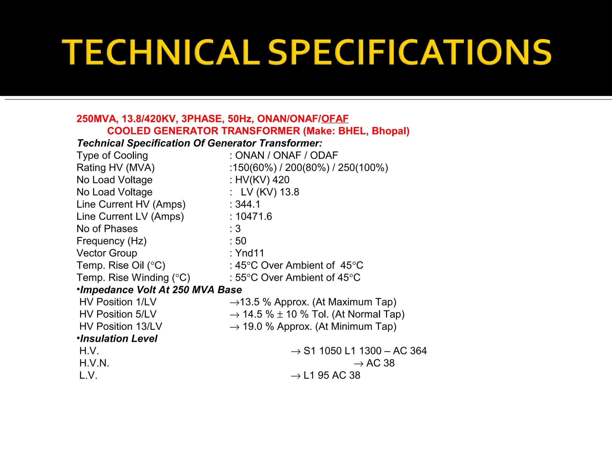
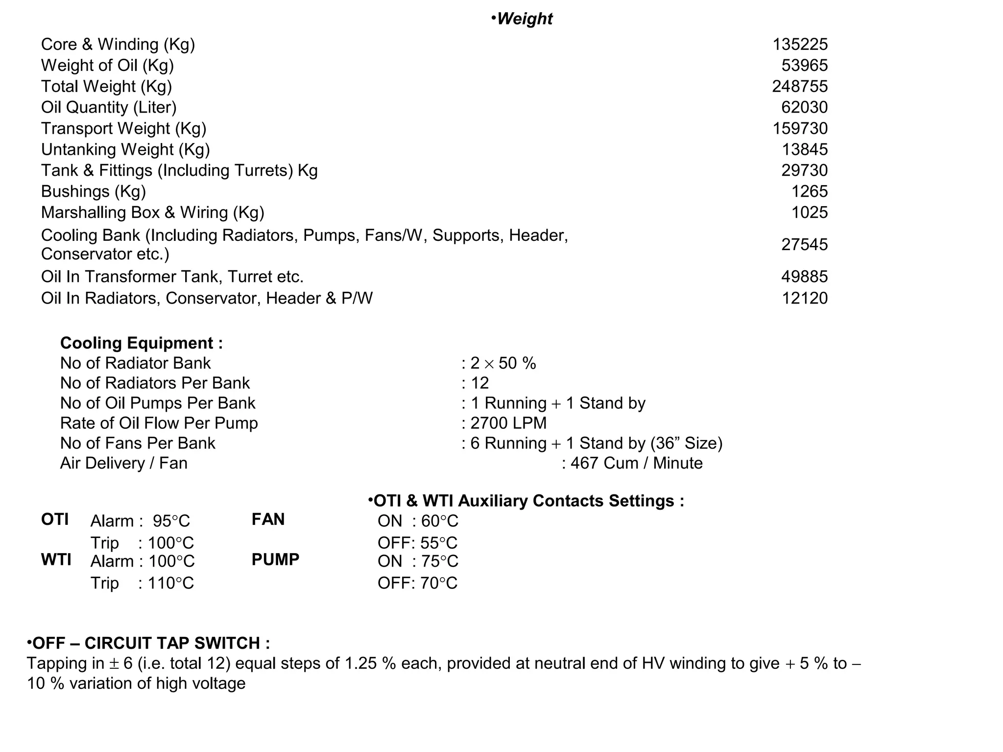
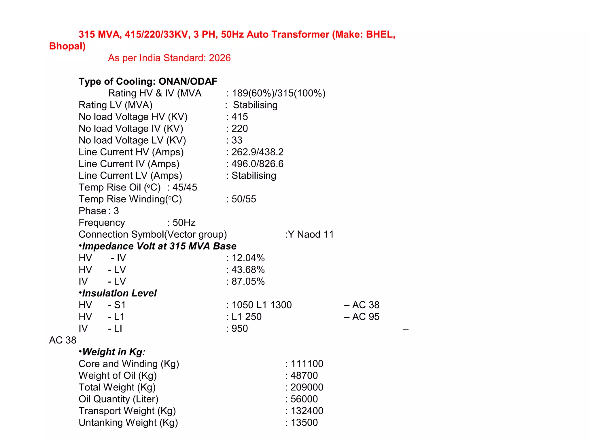
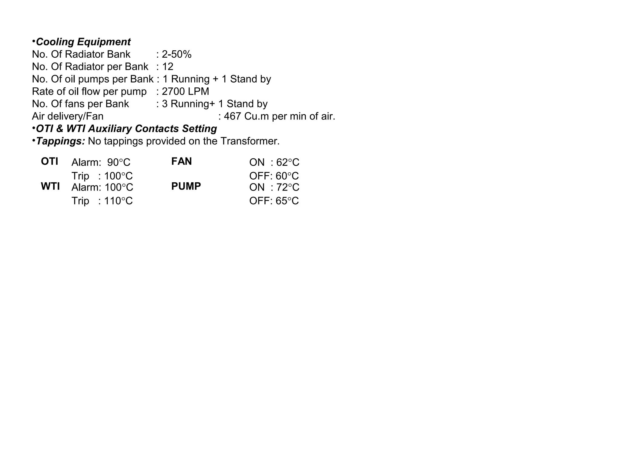
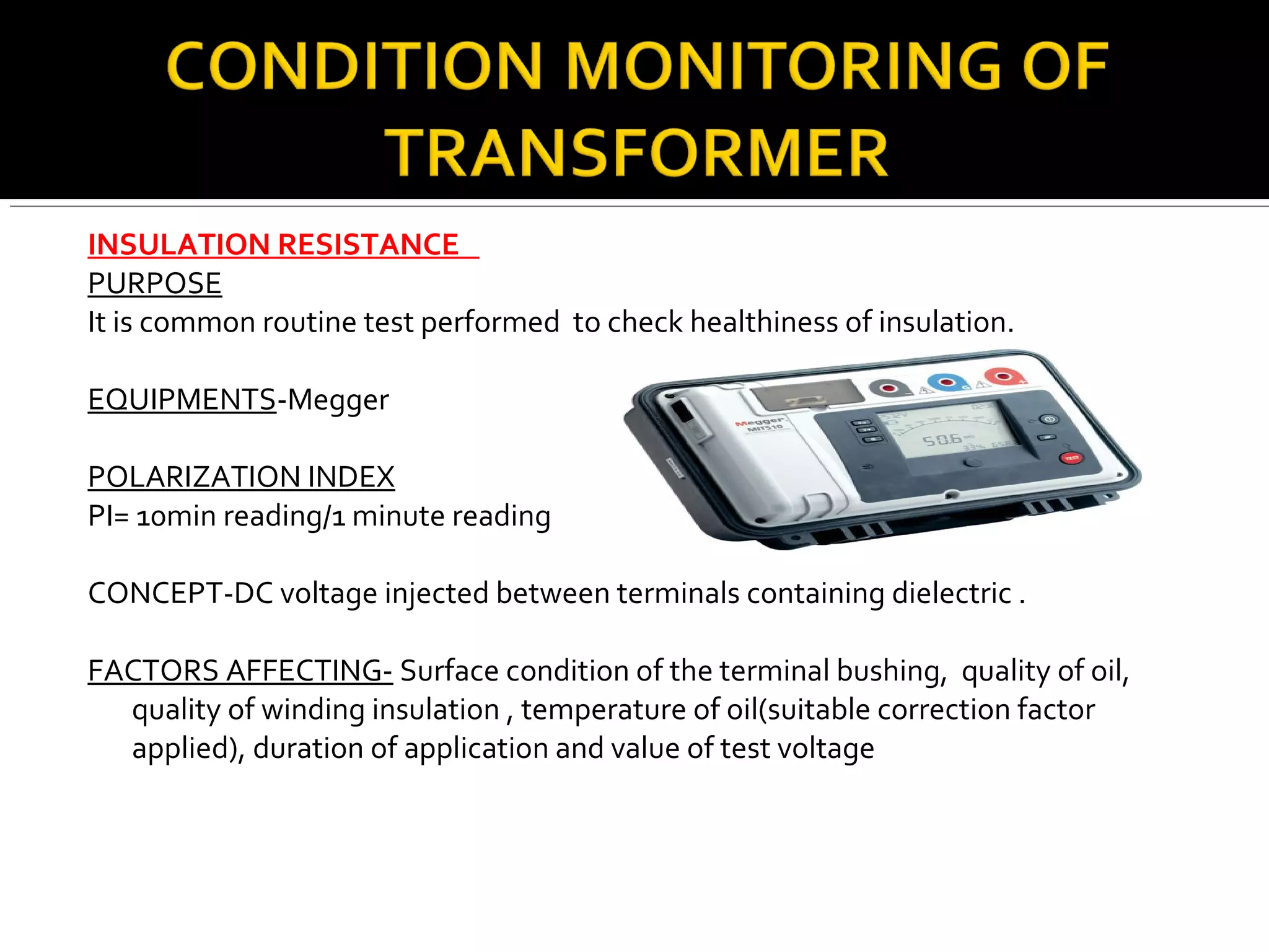
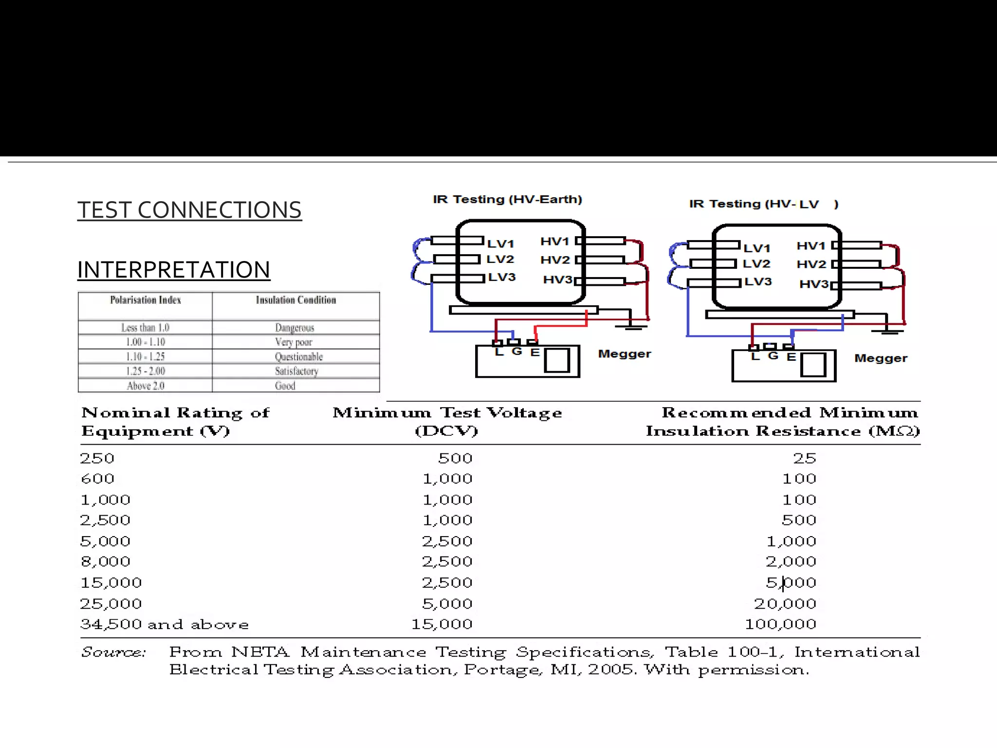
250MVA, 13.8/420KV, 3PHASE, 50Hz, ONAN/ONAF/OFAF
COOLED GENERATOR TRANSFORMER (Make: BHEL, Bhopal)
Technical Specification Of Generator Transformer:
Type of Cooling : ONAN / ONAF / ODAF
Rating HV (MVA) :150(60%) / 200(80%) / 250(100%)
No Load Voltage : HV(KV) 420
No Load Voltage : LV (KV) 13.8
Line Current HV (Amps) : 344.1
Line Current LV (Amps) : 10471.6
No of Phases : 3
Frequency (Hz) : 50
Vector Group : Ynd11
Temp. Rise Oil (°C) : 45°C Over Ambient of 45°C
Temp. Rise Winding (°C) : 55°C Over Ambient of 45°C
•Impedance Volt At 250 MVA Base
HV Position 1/LV →13.5 % Approx. (At Maximum Tap)
HV Position 5/LV → 14.5 % ± 10 % Tol. (At Normal Tap)
HV Position 13/LV → 19.0 % Approx. (At Minimum Tap)
•Insulation Level
H.V. → S1 1050 L1 1300 – AC 364
H.V.N. → AC 38
L.V. → L1 95 AC 38
Core & Winding (Kg) 135225
Weight of Oil (Kg) 53965
Total Weight (Kg) 248755
Oil Quantity (Liter) 62030
Transport Weight (Kg) 159730
Untanking Weight (Kg) 13845
Tank & Fittings (Including Turrets) Kg 29730
Bushings (Kg) 1265
Marshalling Box & Wiring (Kg) 1025
Cooling Bank (Including Radiators, Pumps, Fans/W, Supports, Header,
Conservator etc.)
27545
Oil In Transformer Tank, Turret etc. 49885
Oil In Radiators, Conservator, Header & P/W 12120
•Weight
Cooling Equipment :
No of Radiator Bank : 2 × 50 %
No of Radiators Per Bank : 12
No of Oil Pumps Per Bank : 1 Running + 1 Stand by
Rate of Oil Flow Per Pump : 2700 LPM
No of Fans Per Bank : 6 Running + 1 Stand by (36” Size)
Air Delivery / Fan : 467 Cum / Minute
OTI Alarm : 95°C
Trip : 100°C
FAN ON : 60°C
OFF: 55°C
WTI Alarm : 100°C
Trip : 110°C
PUMP ON : 75°C
OFF: 70°C
•OTI & WTI Auxiliary Contacts Settings :
•OFF – CIRCUIT TAP SWITCH :
Tapping in ± 6 (i.e. total 12) equal steps of 1.25 % each, provided at neutral end of HV winding to give + 5 % to −
10 % variation of high voltage
315 MVA, 415/220/33KV, 3 PH, 50Hz Auto Transformer (Make: BHEL,
Bhopal)
As per India Standard: 2026
Type of Cooling: ONAN/ODAF
Rating HV & IV (MVA : 189(60%)/315(100%)
Rating LV (MVA) : Stabilising
No load Voltage HV (KV) : 415
No load Voltage IV (KV) : 220
No load Voltage LV (KV) : 33
Line Current HV (Amps) : 262.9/438.2
Line Current IV (Amps) : 496.0/826.6
Line Current LV (Amps) : Stabilising
Temp Rise Oil (o
C) : 45/45
Temp Rise Winding(o
C) : 50/55
Phase : 3
Frequency : 50Hz
Connection Symbol(Vector group) :Y Naod 11
•Impedance Volt at 315 MVA Base
HV - IV : 12.04%
HV - LV : 43.68%
IV - LV : 87.05%
•Insulation Level
HV - S1 : 1050 L1 1300 – AC 38
HV - L1 : L1 250 – AC 95
IV - LI : 950 –
AC 38
•Weight in Kg:
Core and Winding (Kg) : 111100
Weight of Oil (Kg) : 48700
Total Weight (Kg) : 209000
Oil Quantity (Liter) : 56000
Transport Weight (Kg) : 132400
Untanking Weight (Kg) : 13500
OTI Alarm: 90°C
Trip : 100°C
FAN ON : 62°C
OFF: 60°C
WTI Alarm: 100°C
Trip : 110°C
PUMP ON : 72°C
OFF: 65°C
•Cooling Equipment
No. Of Radiator Bank : 2-50%
No. Of Radiator per Bank : 12
No. Of oil pumps per Bank : 1 Running + 1 Stand by
Rate of oil flow per pump : 2700 LPM
No. Of fans per Bank : 3 Running+ 1 Stand by
Air delivery/Fan : 467 Cu.m per min of air.
•OTI & WTI Auxiliary Contacts Setting
•Tappings: No tappings provided on the Transformer.
INSULATION RESISTANCE
PURPOSE
It is common routine test performed to check healthiness of insulation.
EQUIPMENTS-Megger
POLARIZATION INDEX
PI= 10min reading/1 minute reading
CONCEPT-DC voltage injected between terminals containing dielectric .
FACTORS AFFECTING- Surface condition of the terminal bushing, quality of oil,
quality of winding insulation , temperature of oil(suitable correction factor
applied), duration of application and value of test voltage
TEST CONNECTIONS
INTERPRETATION
FACTORS AFFECTING- Surface condition of the terminal bushing, quality of oil,
quality of winding insulation , temperature of oil(suitable correction factor
applied), duration of application and value of test voltage
DIELECTRIC ABSORPTION
PURPOSE-The Dielectric Absorption (or Time-Resistance) is an extension of IR.
EQUIPMENT USED-Digital megger with timer
CONCEPT-When voltage is applied to an insulation system, three types of current -
Leakage current- is the resistive current .
Capacitive charging current
Dielectric absorption current -polarising current to align the dipoles.
PROCEDURE
In this test, a test voltage is applied for, usually thirty minutes. The megger
readings are taken every 10 seconds for the first minute and thereafter every
minute – up to 30 minutes. A curve is drawn showing the variation in the value of
IR.
INTERPRETATION-Graph
RATIO
PURPOSE -Check rated LV voltage
at rated HV voltage and tap changer
Operation.
EQUIPMENTS-Multimeter
CONCEPT-HV Volts/LV volts=HV turns/LV turns
MEASUREMENTS(230V AC at HV)
1R1Y,1Y1B,1B1R,2R2Y,2Y2B,2B2R.
INTERPRETATION-From name plate details
SHORT CIRCUIT CURRENT
PURPOSE-Check for any loose contact in the tap changer, lead connections etc.
EQUIPMENT USED-LV 3 phase supply & amperemeter.
CONCEPT-A 3 phase balanced low voltage a.c supply is applied to the HV winding at
rated tap and the current measured. The current measured at rated tap should
tally with the calculated value.Secondary should be S.C.
INTERPRETATION-Value of current obtained
Should tally with calculated value. Difference is
Indication of lose contact of tap changer.
MAGNETISING CURRENT
PURPOSE
Test any fault in the magnetic circuit and winding.
EQUIPMENT USED-
LV 3 phase supply & clamp meter.
CONCEPT
Single phase from 440 volts source applied to each phase and current is measured.
INTERPRETATION Current should be in milliamp and comparable.
MAGNETIC BALANCE
PURPOSE-Find out the condition of stacking of core laminations, tightness of core
bolts and perfection of magnetic circuit..
EQUIPMENT USED-Multimeter.
CONCEPT
HV each phase from source of 440V.
Phase and neutral connection for star-
1u-1n,1v-1n,1w-1n
Phase and neutral connection for delta.
1u-1v, 1v-1w,1w-1u
INTERPRETATION
EXAMPLE-Excited R phase-R phase volts=Y Phase volts+B phase volts
VECTOR GROUP
PURPOSE-Polarity and Phasor relationship between HV and LV voltages.
EQUIPMENT USED-Multi-meter.
CONCEPTVector group shows phase relationship between HV &LV windings
INTERPRETATION-Specific set of equations for particular vector group.
WTI
Tripping & alarm check.
OTI
Tripping & alarm check
PRV
Tripping & alarm check
MOG
Tripping & alarm check
BUCCHOLZ RELAY
Tripping and alarm check.
Floats check.
BREATHER
Check the colour of the silica gel in the breather.
RADIATOR
Check the radiator for release of air and position of valves.
BUSHINGS
Check the oil level in the bushings if sealed bushings are used. Release air from
bushings if air release plugs are provided.
WINDING RESISTANCE
PURPOSE-Resistance of individual winding.
EQUIPMENT USED-Winding resistance kit
CONCEPT-Inter turn fault and winding damage.
INTERPRETATION-Manufacturers recommendations and inter winding comparision.
PURPOSE-
To change tap when transformer is loaded.
CONDITION MONITERING-
Continuity of taps.
Transient resistance.
Condition of rolling and fixed taps.
MAINTENENCE-Servicing.
PURPOSE- IS-10028
Life increase of transformer.
Improvement of IR value. Improvement of quality of oil used.
Minor rectifications . Sludge Removal.
PURPOSE- Determine the degradation of insulation.
Cracks or voids left of created during manufacturing
or ageing.
EQUIPMENT USED-OMNICRON,
DOBLE AND MEGGER are standard
equipment for high voltage equipment.
SCOPE-Transformer winding, Bushings,
Bushing CT, Bushing PT, LA, motors,
Generators, Cables .
MODES- UST, GST & GSTg-A
CONCEPT
Tan delta= Ir/Ic
INTERPRETATION- Value of tan delta should be less than .007 at 20 degree
temperature and capacitance of within 5% variation or as per name plate.
FACTORS AFFECTING-Oil condition, Dirt on surface, Temperature, Loose test co
PURPOSE-
Operate equipment in safe temperature zone.
Loose contacts detection.
Local hot spots.
PURPOSE
SFRA analysis can detect problems in transformers such as:
Winding deformation – axial & radial.
Displacements between high and low voltage winding.
EQUIPMENTS-SFRA kit.
CONCEPT-Transformers consist of multiple complex networks
of capacitances and resistors that can generate a unique signature when tested
at discreet frequencies and plotted as a curve. The distance between conductors
of the transformer forms a capacitance. Any movement of the conductors or
windings will change this capacitance. This capacitance being a part of complex L
(inductance), R (Resistance) and C (Capacitance) network, any change in this
capacitance will be reflected in the curve or signature.
INTERPRETATION
Time-based – current SFRA results compared to previous results of the same unit.
Type-based–SFRA of one transformer will be compared to equal type of
transformer.
Phase comparison – SFRA results of one phase will be compared to the results of the
other phases of the same transformer.
PURPOSE
Oil analysis of switchgear elements like OCB, Transformers, CT, PT etc. is important
not only for smooth operation but also for faults detection inside these
equipments
ABBREVATIONS- O- Power Transformer above 420kv
A- Power Transformer 170kv-420kv
B- Power Transformer 72.5kv-170kv
C-Power Transformer up to 72.5kv
D-Instrument Transformer above170Kv
E-Instrument Transformer up to 170Kv
G-OCB
WATER CONTENT
IS-13567
PURPOSE-Effects insulation quality and
decrease BDV.
LIMIT(PPM) OAD-00 ,B-40 , E-30, C-50
BREAK DOWN VOLTAGE
IS-6792
PURPOSE- To avoid sparking.
LIMIT(KV rms) OAD-50 ,BE-40 ,C -30
DIELECTRIC DISSIPATION FACTOR AT & SPECIFIC RESISTANCE OR
RESISTIVITY AT 90 DEGREE
IS-6262
PURPOSE- Property of good dielectric.
LIMIT(%) OAD-0.20 ,BE-1,C -.30
IS-6103
PURPOSE Property of good dielectric.
LIMIT(ohm-cm)-0.1*10^12
INTERFACIAL TENSION
IS-6104
PURPOSE-molecular attractive forces
Between water and oil
LIMIT(N/m)-0.015
FLASH POINT
IS-1448
PURPOSE-avoid flash as temperature rises.
LIMIT(degree celcius)-125
NEUTRALIZATION VALUE
IS-1448
PURPOSE- Acidity degrades paper insulation
LIMIT(mgKOH/gm) -0.3000
FURON ANALYSIS
IS-9434
PURPOSE-To detect healthy condition of paper insulation.
LIMIT(PPM) -1.001
DISSOLVE GAS ANALYSIS
IS-9435
PURPOSE-To detect faults inside transformer.
LIMIT(PPM)
GAS INDICATIVE FAULT LIMIT
METHANE LOCAL OVERHEATING 120
ETHYLENE THERMAL DEGRADATION OF
OIL
50
ETHANE OVERHEATING 65
ACETYLENE ARCING & SPARKING 35
HYDROGEN ELECTRICAL/THERMAL FAULT 100
CARBON MONOXIDE THERMAL AGEING OF PAPER 350
FOLLOWING PARAMETERS SHOULD BE MONITERED PERIODICALLY-
1.CLOSING TIME-150ms
2.TRIP TIME-150ms
3.TAN DELTA OF GRADING CAPACITORS-.007
4.CONTACT RESISTANCE-150m-ohm
5. IR VALUE-1000mega-ohm
FOLLOWING PARAMETERS SHOULD BE MONITERED PERIODICALLY-
1.IR-1000Mega ohm
2.TAN DELTA-.007
3.CT RATIO ERRORS FOR PROTECTION CORES-+3%
4. CT RATIO ERRORS FOR METERING CORES-+3%
5.CURRENT IN METERING AND PROTECTION CIRCUITS
6.CAPACITANCE-+10%&-5%
FOLLOWING PARAMETERS SHOULD BE MONITERED PERIODICALLY-
1.IR-1000Mega ohm
2.TAN DELTA-.007
3.CVT RATIO ERRORS FOR PROTECTION CORES-+5%
4. CVT RATIO ERRORS FOR METERING CORES-+0.5%
5.CURRENT IN METERING AND PROTECTION CIRCUITS.
6.CAPACITANCE-+10%&-5%
FOLLOWING PARAMETERS SHOULD BE MONITERED PERIODICALLY-
LEAKAGE CURREAT-500m-amp
IR VALUE-1000 M-OHM
FOLLOWING PARAMETERS SHOULD BE MONITERED PERIODICALLY-
TRIPPING TIME
CLOSING TIME
RESET VALUE
PICK UP VALUE
Testing and Condition Monitoring of Substation Equipments

Testing and Condition Monitoring of Substation Equipments

  • 3.
    250MVA, 13.8/420KV, 3PHASE,50Hz, ONAN/ONAF/OFAF COOLED GENERATOR TRANSFORMER (Make: BHEL, Bhopal) Technical Specification Of Generator Transformer: Type of Cooling : ONAN / ONAF / ODAF Rating HV (MVA) :150(60%) / 200(80%) / 250(100%) No Load Voltage : HV(KV) 420 No Load Voltage : LV (KV) 13.8 Line Current HV (Amps) : 344.1 Line Current LV (Amps) : 10471.6 No of Phases : 3 Frequency (Hz) : 50 Vector Group : Ynd11 Temp. Rise Oil (°C) : 45°C Over Ambient of 45°C Temp. Rise Winding (°C) : 55°C Over Ambient of 45°C •Impedance Volt At 250 MVA Base HV Position 1/LV →13.5 % Approx. (At Maximum Tap) HV Position 5/LV → 14.5 % ± 10 % Tol. (At Normal Tap) HV Position 13/LV → 19.0 % Approx. (At Minimum Tap) •Insulation Level H.V. → S1 1050 L1 1300 – AC 364 H.V.N. → AC 38 L.V. → L1 95 AC 38
  • 4.
    Core & Winding(Kg) 135225 Weight of Oil (Kg) 53965 Total Weight (Kg) 248755 Oil Quantity (Liter) 62030 Transport Weight (Kg) 159730 Untanking Weight (Kg) 13845 Tank & Fittings (Including Turrets) Kg 29730 Bushings (Kg) 1265 Marshalling Box & Wiring (Kg) 1025 Cooling Bank (Including Radiators, Pumps, Fans/W, Supports, Header, Conservator etc.) 27545 Oil In Transformer Tank, Turret etc. 49885 Oil In Radiators, Conservator, Header & P/W 12120 •Weight Cooling Equipment : No of Radiator Bank : 2 × 50 % No of Radiators Per Bank : 12 No of Oil Pumps Per Bank : 1 Running + 1 Stand by Rate of Oil Flow Per Pump : 2700 LPM No of Fans Per Bank : 6 Running + 1 Stand by (36” Size) Air Delivery / Fan : 467 Cum / Minute OTI Alarm : 95°C Trip : 100°C FAN ON : 60°C OFF: 55°C WTI Alarm : 100°C Trip : 110°C PUMP ON : 75°C OFF: 70°C •OTI & WTI Auxiliary Contacts Settings : •OFF – CIRCUIT TAP SWITCH : Tapping in ± 6 (i.e. total 12) equal steps of 1.25 % each, provided at neutral end of HV winding to give + 5 % to − 10 % variation of high voltage
  • 5.
    315 MVA, 415/220/33KV,3 PH, 50Hz Auto Transformer (Make: BHEL, Bhopal) As per India Standard: 2026 Type of Cooling: ONAN/ODAF Rating HV & IV (MVA : 189(60%)/315(100%) Rating LV (MVA) : Stabilising No load Voltage HV (KV) : 415 No load Voltage IV (KV) : 220 No load Voltage LV (KV) : 33 Line Current HV (Amps) : 262.9/438.2 Line Current IV (Amps) : 496.0/826.6 Line Current LV (Amps) : Stabilising Temp Rise Oil (o C) : 45/45 Temp Rise Winding(o C) : 50/55 Phase : 3 Frequency : 50Hz Connection Symbol(Vector group) :Y Naod 11 •Impedance Volt at 315 MVA Base HV - IV : 12.04% HV - LV : 43.68% IV - LV : 87.05% •Insulation Level HV - S1 : 1050 L1 1300 – AC 38 HV - L1 : L1 250 – AC 95 IV - LI : 950 – AC 38 •Weight in Kg: Core and Winding (Kg) : 111100 Weight of Oil (Kg) : 48700 Total Weight (Kg) : 209000 Oil Quantity (Liter) : 56000 Transport Weight (Kg) : 132400 Untanking Weight (Kg) : 13500
  • 6.
    OTI Alarm: 90°C Trip: 100°C FAN ON : 62°C OFF: 60°C WTI Alarm: 100°C Trip : 110°C PUMP ON : 72°C OFF: 65°C •Cooling Equipment No. Of Radiator Bank : 2-50% No. Of Radiator per Bank : 12 No. Of oil pumps per Bank : 1 Running + 1 Stand by Rate of oil flow per pump : 2700 LPM No. Of fans per Bank : 3 Running+ 1 Stand by Air delivery/Fan : 467 Cu.m per min of air. •OTI & WTI Auxiliary Contacts Setting •Tappings: No tappings provided on the Transformer.
  • 7.
    INSULATION RESISTANCE PURPOSE It iscommon routine test performed to check healthiness of insulation. EQUIPMENTS-Megger POLARIZATION INDEX PI= 10min reading/1 minute reading CONCEPT-DC voltage injected between terminals containing dielectric . FACTORS AFFECTING- Surface condition of the terminal bushing, quality of oil, quality of winding insulation , temperature of oil(suitable correction factor applied), duration of application and value of test voltage
  • 8.
  • 9.
    FACTORS AFFECTING- Surfacecondition of the terminal bushing, quality of oil, quality of winding insulation , temperature of oil(suitable correction factor applied), duration of application and value of test voltage DIELECTRIC ABSORPTION PURPOSE-The Dielectric Absorption (or Time-Resistance) is an extension of IR. EQUIPMENT USED-Digital megger with timer CONCEPT-When voltage is applied to an insulation system, three types of current - Leakage current- is the resistive current . Capacitive charging current Dielectric absorption current -polarising current to align the dipoles.
  • 10.
    PROCEDURE In this test,a test voltage is applied for, usually thirty minutes. The megger readings are taken every 10 seconds for the first minute and thereafter every minute – up to 30 minutes. A curve is drawn showing the variation in the value of IR. INTERPRETATION-Graph RATIO PURPOSE -Check rated LV voltage at rated HV voltage and tap changer Operation. EQUIPMENTS-Multimeter CONCEPT-HV Volts/LV volts=HV turns/LV turns
  • 11.
    MEASUREMENTS(230V AC atHV) 1R1Y,1Y1B,1B1R,2R2Y,2Y2B,2B2R. INTERPRETATION-From name plate details SHORT CIRCUIT CURRENT PURPOSE-Check for any loose contact in the tap changer, lead connections etc. EQUIPMENT USED-LV 3 phase supply & amperemeter. CONCEPT-A 3 phase balanced low voltage a.c supply is applied to the HV winding at rated tap and the current measured. The current measured at rated tap should tally with the calculated value.Secondary should be S.C.
  • 12.
    INTERPRETATION-Value of currentobtained Should tally with calculated value. Difference is Indication of lose contact of tap changer. MAGNETISING CURRENT PURPOSE Test any fault in the magnetic circuit and winding. EQUIPMENT USED- LV 3 phase supply & clamp meter. CONCEPT Single phase from 440 volts source applied to each phase and current is measured. INTERPRETATION Current should be in milliamp and comparable.
  • 13.
    MAGNETIC BALANCE PURPOSE-Find outthe condition of stacking of core laminations, tightness of core bolts and perfection of magnetic circuit.. EQUIPMENT USED-Multimeter. CONCEPT HV each phase from source of 440V. Phase and neutral connection for star- 1u-1n,1v-1n,1w-1n Phase and neutral connection for delta. 1u-1v, 1v-1w,1w-1u INTERPRETATION EXAMPLE-Excited R phase-R phase volts=Y Phase volts+B phase volts
  • 14.
    VECTOR GROUP PURPOSE-Polarity andPhasor relationship between HV and LV voltages. EQUIPMENT USED-Multi-meter. CONCEPTVector group shows phase relationship between HV &LV windings INTERPRETATION-Specific set of equations for particular vector group.
  • 15.
    WTI Tripping & alarmcheck. OTI Tripping & alarm check PRV Tripping & alarm check MOG Tripping & alarm check
  • 16.
    BUCCHOLZ RELAY Tripping andalarm check. Floats check. BREATHER Check the colour of the silica gel in the breather. RADIATOR Check the radiator for release of air and position of valves. BUSHINGS Check the oil level in the bushings if sealed bushings are used. Release air from bushings if air release plugs are provided.
  • 17.
    WINDING RESISTANCE PURPOSE-Resistance ofindividual winding. EQUIPMENT USED-Winding resistance kit CONCEPT-Inter turn fault and winding damage. INTERPRETATION-Manufacturers recommendations and inter winding comparision.
  • 18.
    PURPOSE- To change tapwhen transformer is loaded. CONDITION MONITERING- Continuity of taps. Transient resistance. Condition of rolling and fixed taps. MAINTENENCE-Servicing.
  • 19.
    PURPOSE- IS-10028 Life increaseof transformer. Improvement of IR value. Improvement of quality of oil used. Minor rectifications . Sludge Removal.
  • 20.
    PURPOSE- Determine thedegradation of insulation. Cracks or voids left of created during manufacturing or ageing. EQUIPMENT USED-OMNICRON, DOBLE AND MEGGER are standard equipment for high voltage equipment. SCOPE-Transformer winding, Bushings, Bushing CT, Bushing PT, LA, motors, Generators, Cables .
  • 21.
    MODES- UST, GST& GSTg-A CONCEPT Tan delta= Ir/Ic INTERPRETATION- Value of tan delta should be less than .007 at 20 degree temperature and capacitance of within 5% variation or as per name plate. FACTORS AFFECTING-Oil condition, Dirt on surface, Temperature, Loose test co
  • 22.
    PURPOSE- Operate equipment insafe temperature zone. Loose contacts detection. Local hot spots.
  • 23.
    PURPOSE SFRA analysis candetect problems in transformers such as: Winding deformation – axial & radial. Displacements between high and low voltage winding. EQUIPMENTS-SFRA kit. CONCEPT-Transformers consist of multiple complex networks of capacitances and resistors that can generate a unique signature when tested at discreet frequencies and plotted as a curve. The distance between conductors of the transformer forms a capacitance. Any movement of the conductors or windings will change this capacitance. This capacitance being a part of complex L (inductance), R (Resistance) and C (Capacitance) network, any change in this capacitance will be reflected in the curve or signature.
  • 24.
    INTERPRETATION Time-based – currentSFRA results compared to previous results of the same unit. Type-based–SFRA of one transformer will be compared to equal type of transformer. Phase comparison – SFRA results of one phase will be compared to the results of the other phases of the same transformer.
  • 25.
    PURPOSE Oil analysis ofswitchgear elements like OCB, Transformers, CT, PT etc. is important not only for smooth operation but also for faults detection inside these equipments ABBREVATIONS- O- Power Transformer above 420kv A- Power Transformer 170kv-420kv B- Power Transformer 72.5kv-170kv C-Power Transformer up to 72.5kv D-Instrument Transformer above170Kv E-Instrument Transformer up to 170Kv G-OCB
  • 26.
    WATER CONTENT IS-13567 PURPOSE-Effects insulationquality and decrease BDV. LIMIT(PPM) OAD-00 ,B-40 , E-30, C-50 BREAK DOWN VOLTAGE IS-6792 PURPOSE- To avoid sparking. LIMIT(KV rms) OAD-50 ,BE-40 ,C -30
  • 27.
    DIELECTRIC DISSIPATION FACTORAT & SPECIFIC RESISTANCE OR RESISTIVITY AT 90 DEGREE IS-6262 PURPOSE- Property of good dielectric. LIMIT(%) OAD-0.20 ,BE-1,C -.30 IS-6103 PURPOSE Property of good dielectric. LIMIT(ohm-cm)-0.1*10^12
  • 28.
    INTERFACIAL TENSION IS-6104 PURPOSE-molecular attractiveforces Between water and oil LIMIT(N/m)-0.015 FLASH POINT IS-1448 PURPOSE-avoid flash as temperature rises. LIMIT(degree celcius)-125
  • 29.
    NEUTRALIZATION VALUE IS-1448 PURPOSE- Aciditydegrades paper insulation LIMIT(mgKOH/gm) -0.3000 FURON ANALYSIS IS-9434 PURPOSE-To detect healthy condition of paper insulation. LIMIT(PPM) -1.001
  • 30.
    DISSOLVE GAS ANALYSIS IS-9435 PURPOSE-Todetect faults inside transformer. LIMIT(PPM) GAS INDICATIVE FAULT LIMIT METHANE LOCAL OVERHEATING 120 ETHYLENE THERMAL DEGRADATION OF OIL 50 ETHANE OVERHEATING 65 ACETYLENE ARCING & SPARKING 35 HYDROGEN ELECTRICAL/THERMAL FAULT 100 CARBON MONOXIDE THERMAL AGEING OF PAPER 350
  • 31.
    FOLLOWING PARAMETERS SHOULDBE MONITERED PERIODICALLY- 1.CLOSING TIME-150ms 2.TRIP TIME-150ms 3.TAN DELTA OF GRADING CAPACITORS-.007 4.CONTACT RESISTANCE-150m-ohm 5. IR VALUE-1000mega-ohm
  • 32.
    FOLLOWING PARAMETERS SHOULDBE MONITERED PERIODICALLY- 1.IR-1000Mega ohm 2.TAN DELTA-.007 3.CT RATIO ERRORS FOR PROTECTION CORES-+3% 4. CT RATIO ERRORS FOR METERING CORES-+3% 5.CURRENT IN METERING AND PROTECTION CIRCUITS 6.CAPACITANCE-+10%&-5%
  • 33.
    FOLLOWING PARAMETERS SHOULDBE MONITERED PERIODICALLY- 1.IR-1000Mega ohm 2.TAN DELTA-.007 3.CVT RATIO ERRORS FOR PROTECTION CORES-+5% 4. CVT RATIO ERRORS FOR METERING CORES-+0.5% 5.CURRENT IN METERING AND PROTECTION CIRCUITS. 6.CAPACITANCE-+10%&-5%
  • 34.
    FOLLOWING PARAMETERS SHOULDBE MONITERED PERIODICALLY- LEAKAGE CURREAT-500m-amp IR VALUE-1000 M-OHM
  • 35.
    FOLLOWING PARAMETERS SHOULDBE MONITERED PERIODICALLY- TRIPPING TIME CLOSING TIME RESET VALUE PICK UP VALUE