The document summarizes different types of excitation systems used for synchronous generators. It describes the components and operation of static excitation systems, which are now widely used. Static excitation systems provide fast acting voltage control using thyristor bridges and power electronics. They allow high response ratios of 3-5 compared to older systems like DC excitation. The key components of a static excitation system are the rectifier transformer, SCR bridges, excitation start up equipment, field discharge equipment, and regulator/control circuits.
1 19-03-04
PDF created with pdfFactory Pro trial version www.pdffactory.com
2.
EXCITATION SYSTEM
INTRODUCTION
All synchronous machines excepting certain machines like permanent magnet
generators require a DC supply to excite their field winding. As synchronous machine is a
constant speedy machine for a constant frequency supply, the output voltage of the machine
depends on the excitation current. The control of excitation current for maintaining constant
voltage at generator output terminals started with control through a field rheostat, the supply
being obtained from DC Exciter. The modern trend in interconnected operation of power
systems for the purpose of reliability and in increasing unit size of generators for the
purposes of economy has been mainly, responsible for the evolution of new excitation
schemes.
Former practice, to have an excitation bus fed by a number of exciters operating in
parallel and supplying power to the fields of all the alternators in the station, is now obsolete.
The present practice is unit exciter scheme, i.e. each alternator to have its own exciter.
However in some plants reserve bus exciter/stand by exciter also provided in case of failure
of unit exciter (Fig. 1)
Exciter should be capable of supplying necessary excitation for alternator in a
reasonable period during normal and abnormal conditions, so that alternator will be in
synchronism with the grid.
THE RATING OF THE EXCITER
Under normal conditions, exciter rating will be in the order of 0.3 to 0.6% of
generator rating (approx.). Its rating also expressed in 10 to 15 amp. (approx.) per MW at
normal load. Under field forcing conditions exciter rating will be 1 to 1.5% (approx) of the
generator rating. Typical exciter ratings for various capacity of generators are as given
below:
2 19-03-04
PDF created with pdfFactory Pro trial version www.pdffactory.com
3.
EXCITER RATINGS FORDIFFERENT CAPACITIES OF GENERATORS
INSTALLED IN INDIA (UPTO 210 MW)
TURBO GENERATOR
1 Max. Continuous rating (MW) 210 110 100 60 50
2 Rated Power factor 0.85 0.8 0.85 0.873 0.8
3 Rated Terminal Voltage (in KV) 15.75 11 10.5 11 10.5
4 Rated current (Amp.) 9050 7220 6480 3250 3440
EXCITER
5 Slip ring voltage at full load condition(V) 310 440 280.1 350 240
6 Excitation current at MCR condition (Amp) 2600 1500 1680 800 667
7 Rated output (KW) 806 660 470 280 160
8 Ex. Rating in % of Gen. rating 0.38 0.6 0.47 0.47 0.32
TYPES OF THE EXCITATION SYSTEM
There are two types of Excitation System. These are mainly classified as (i) Dynamic
exciter (rotating type) (ii) Static Exciter (static type). The different types excitation which
are being used are indicated as given below :
(1) (a) Separately Excited (thro' pilot exciter) (DC) Excitation System
(b) Self Excited (shunt) (DC) Excitation System
(2) High frequency AC Excitation System
(3) Brushless Excitation System
(4) Static Excitation System
Among the above types of exciters, Static excitation system plays a very important
roll in modern interconnected power system operation due to its fast acting, good response in
voltage & reactive power control and satisfactory steady state stability condition. For the
machines 500 MW & above and fire hazards areas, Brushless Excitation System is preferred
due to larger requirement of current & plant safety respectively.
3 19-03-04
PDF created with pdfFactory Pro trial version www.pdffactory.com
4.
THE RELATIVE MERITSOF DIFFERENT EXCITERS ARE LISTED AS GIVEN BELOW:
VARIOUS EXCITATION SYSTEMS AND THEIR RELATIVE MERITS
1. TYPE STATIC EXCITER DC EXCITER AC EXCITER WITH BRUSHLESS
STATIONARY DIODES
2. COMPOUNDING YES YES YES ------
INCLUDED
3. EXCITATION TRANSFORMER & SMALL TRAFO SMALL TRAFO SMALL TRAFO
SUPPLY COMPOUNDING
TRAFO
4. LENGTH OF SHORT MEDIUM MEDIUM LONGER
MACHINE
5. CONTROL VERY FAST SLOWER SLOWER SLOWER
RESPONSE
6. PROTECTION GOOD GOOD GOOD GOOD
SELECTIVITY
7. RESPONSE FLEXIBLE LIMITED LIMITED LIMITED
RATIO
SELECTION
8. COMPONENT SLIPRING SLIPRING & SLIPRING NONE
REQUIRING COMMUTATOR
MAINTENANCE
9. FAST DE- YES YES YES NO
EXCITATION
INTRODUCTION TO STATIC EXCITATION EQUIPMENTF ITS SALIENT FEATURES AND
COMPARISON WITH OTHER SYSTEMS:
At present various type of excitation systems, such as, conventional DC, High
frequency AC, Static & Brushless are being adopted in India and abroad.
The conventional DC exciter was the unchallenged source of Generator Excitation for
nearly fifty years till the rating of turbo-generators reached around 10OMW. In the last three
to four decades, alternative arrangements have been widely adopted because of limitations of
the DC exciters. With increase in generator ratings, it is no longer enough to consider the
exciter used as earlier. Instead, the performance of the whole excitation system including the
automatic voltage regulator and the response of the main generator have to be considered.
Techno econ6mic considerations, grid requirements, reliability and easy maintenance have
become prime considerations.
4 19-03-04
PDF created with pdfFactory Pro trial version www.pdffactory.com
5.
TYPES OF EXCITATIONSYSTEMS (TYPICAL) 1. CONVENTIONAL D.C. EXCITER
The earliest AC turbine generators obtained their excitation supply from the power
station direct current distribution system. Each machine had a rheostat in series with its
field winding to permit adjustment of the terminal voltage and reactive load. This method
was suitable for machines which needed small field power and low internal reactance. As
generator sizes increased excitation power requirements also increased and it became
increasingly desirable for each unit to be self sufficient for excitation and thus the shaft
driven DC exciter was introduced.
2. AC (HIGH FREQUENCY) EXCITATION SYSTEM:
This system was developed to avoid commutator and Brush Gear assembly. In this
system, a shaft driven AC pilot exciter, which has a rotating permanent magnetic field and
a stationary armature, feeds the DC field current of the main high frequency AC exciter
through controlled rectifiers. The high frequency output of the stationary armature is
rectified by stationary diodes and fed via slip-rings to the field of the main turbo generator.
A response ratio of about two can be achieved.
3. BRUSHLESS SYSTEM:
Supply of high current by means of slip rings involves considerable operational
problems and it requires suitable design of slip rings and brush gear.
In brushless excitation system diode rectifiers are mounted on the generator shaft and
their output is directly connected to the field of the alternator thus eliminating brushes and
slip rings. This arrangement necessitates the use of a rotating armature and stationary field
system for the main AC exciter. The voltage regulator final stage takes the form of a
thyristor bridge controlling the field of the main AC exciter which is fed from PMG on the
same shaft. The response ratio of brushless excitation system is normally about two.
5 19-03-04
PDF created with pdfFactory Pro trial version www.pdffactory.com
6.
4. STATIC EXCITATION SYSTEM:
In order to maintain system stability in interconnected system network it is necessary
to have fast acting excitation system for large synchronous machines which means the field
current must be adjusted extremely fast to the changing operational conditions. Besides
maintaining the field current and steady state stability the excitation system is required to
extend the stability limits. It is because of these reasons the static excitation system is
preferred to conventional excitation systems.
In this system, the AC power is tapped off from the generator terminal stepped down
and rectified by fully controlled thyristor Bridges and then fed to the generator field thereby
controlling the generator voltage output. A high control speed is achieved by using an
internal free control and power electronic system. Any deviation in the generator terminal
voltage is sensed by an error detector and causes the voltage regulator to advance or retard
the firing angle of the thyristors thereby controlling the field excitation of the alternator.
In Fig.2 SI.No.(4) Shows a block diagram for a static excitation system. Static
Excitation system can be designed without any difficulty to achieve high response ratio
which is required by the system. The response ratio in the order of 3 to 5 -can be achieved
by this system.
This equipment controls the generator terminal voltage, and hence the reactive load
flow by adjusting the excitation current. The rotating exciter is dispensed with and
Transformer & silicon controlled rectifiers (SCRS) are used which directly feed the field of
the Alternator.
Description of Static Excitation System.
Static Excitation Equipment Consist of
1) Rectifier Transformer
2) SCR output stage
3) Excitation start up & field discharge equipment
6 19-03-04
PDF created with pdfFactory Pro trial version www.pdffactory.com
7.
4) Regulator and operational control circuits
In the above 1, 2, 3 are power Circuit of Static Excitation System 4 is control Circuit of
Static Excitation System.
Rectifier Transformer:
The excitation power is taken from generator output and fed through the excitation
(rectifier) transformer which steps down to the required voltage, for the SCR bridge and then
fed through the field breaker to the generator field. The rectifier transformer used in the SEE
should have high reliability as failure of this will cause shutdown of unit/power station.
Dry type cast coil transformer is suitable for static excitation applications. The
transformer is selected such that it supplies rated excitation current at rated voltage
continuously and is capable of supplying ceiling current at the ceiling excitation for a short
period of ten seconds.
SCR OUTPUT STAGE :
The SCR output stage consists of a suitable number of bridges connected in parallel.
Each thyristor bridge comprises of six thyristors, working as a six pulse fully controlled
bridge. Current carrying capacity of each bridge depends on the rating of individual
thyristor. Thyristors are designed such that their junction temperature rise is well within its
specified rating. By changing the firing angle of the thyristors variable output is obtained.
Each bridge is controlled by one final pulse stage and is cooled by a fan.
These bridges are equipped with protection devices and failure of one bridge causes
alarm. If there is a failure of one more thyristor bridges then the excitation current will be
limited to a predetermined value lesser than the normal current. However, failure of the
third, bridge results in tripping and rapid de-excitation of the generator. The above is
applicable for 4 bridges thyristor with (n-1) principle operation.
7 19-03-04
PDF created with pdfFactory Pro trial version www.pdffactory.com
8.
EXCITATION START UPAND FIELD DISCHARGE EQUIPMENT:
For the initial build-up of the generator voltage, a field-flashing equipment is
required. The rating of this equipment depends on the no-load excitation requirement and
field time constant of the generator. From the reliability point of view, provision for both the
AC & DC field flashing are provided.
The field breaker is selected such that it carries the full load excitation current
continuously and also it breaks the max. field current when the three phase short circuit
occurs at the generator terminals.
The field discharge resistor is normally of non-linear type for medium and large
capacity machines i.e. voltage dependent resistor.
To protect the field winding of the generator against over voltages, an over voltage
protection along with a current limiting resistor is used to limit the over voltage across the
field winding. The OVP operates on the insulation break over Principle. The voltage level
at which OVP should operate is selected based on insulation level of field winding of the
generator.
REGULATOR & OPERATIONAL CONTROL CIRCUITS (CONTROL ELECTRONICS) :
Regulator is the heart of the system. This regulates the generator voltage by
controlling the firing pulses to the thyristors.
a) ERROR DETECTOR & AMPLIFIER:
The Generator terminal voltage is stepped down by a three phase PT.and fed to the
AVR. The a.c. input thus obtained is rectified, filtered and compared against a highly
stabilized reference value and the difference is amplified in different stages of amplification.
The AVR is designed with highly stable elements so that variation in ambient temperature
does not cause any drift or change in the output level. Three CTs sensing the output current
of the generator feed proportional current across variable resistors in the AVR. The voltage
thus obtained across the resistors, can be added vectorially either for compounding or for
transformer drop compensation. The percentage of compensation can be adjusted as the
resistors are of variable type.
8 19-03-04
PDF created with pdfFactory Pro trial version www.pdffactory.com
9.
b) GRID - CONTROL UNIT:
The output of the AVR is fed to a grid control unit, it gets its synchronous a.c.
reference through a filter circuit and generates six double, pulses spaced 600 electrical apart
whose position depends on the output of the AVR, i.e. the pulse position varies continuously
as a function of the control voltage. Two relays are provided, by energising which, the
pulses can be either blocked completely or shifted to inverter mode of operation.
c) PULSE - AMPLIFIER:
The pulse output of the ""Grid control unit "' is amplified further at an intermediate
stage amplification. This is also known as pulse intermediate stage. The unit has a d.c.
power supply, which operates from a three phase 38OV supply and delivers +15V,1 –
l5V,+5V, and a coarse stabilized voltage VL. A built in relay is provided which can be used
for blocking the 6 pulse channels. In a two channel system (like Auto and Manual), the
change over is effected by energising/ de-energizing the relay.
d) PULSE FINAL STAGE:
This unit receives input pulses from the pulse amplifier and transmits them through
pulse transformers to the gates of the thyristors. A built in power supply provides the
required d.c. supply to the final pulse and amplifier. Each Thyristor bridge has its own final
pulse stage. Therefore, even if a thyristor bridge fails with its final pulse stage, the
remaining thyristors bridges can continue to cater to full load requirement of the machine
and thereby ensure (n-1) operation.
e) MANUALCONTROLCHANNEL:
A separate manual control channel is provided where the controlling d.c. signal in
taken from a stabilized d.c. voltage through a motor operated potentiometer. The d.c. signal
is fed to a separate grid control unit whose output pulses after being amplified at an
intermediate stage can be fed to the final pulse stage. When one channel is working,
generating the required pulses, the other remains blocked. Therefore a changeover from
""Auto" to "Manual' control or vice versa is effected by blocking or releasing the pulses of
the corresponding intermediate stage.
9 19-03-04
PDF created with pdfFactory Pro trial version www.pdffactory.com
10.
"A pulse supervisionunit detects spurious pulses or loss of pulses at the pulses bus
bar and transfers control from Automatic Channel to manual channel.
f) FOLLOW-UP UNIT:
To ensure a smooth changeover from 'Auto"' to Manual" control, it is necessary that
the position of the pulses on both channels should be identical. A pulse comparison unit
detects any difference in the position of the pulses and with the help of a follow-up unit
actuates the motor operated potentiometer on the "'Manual"' Channel to turn in a direction so
as to eliminate the difference.
However, while transferring control from "Manual"' to "Auto" mode any difference in
the two control levels can be visually checked on a balance meter and adjusted to obtain null
before change over.
g) LIMIT CONTROLLERS:
When a generator is running in parallel with the power network, it is essential to
maintain it in sychronism without exceeding the rating of the machine and also without the
protection system tripping. Only automatic Regulator cannot ensure this. It is necessary to
influence the voltage regulator by suitable means to limit the over excitation and under
excitation. This not only improves the security of the parallel operation but makes operation
of the system easier. However limiters do not replace the protection system but only prevent
the protection system from tripping unnecessarily under extreme transient.conditions.
The AVR also has a built-in frequency dependent circuit so that when the machine is
running below the rated frequency from the regulated voltage should be proportional to
frequency. With the help of a potentiometer provided in the AVR, the circuit can be made to
respond proportionally to voltage above a certain frequency and proportional to a voltage
below the certain frequency. The range of adjustment of this cut off frequency lies between
40 and 60 Hz.
10 19-03-04
PDF created with pdfFactory Pro trial version www.pdffactory.com
11.
The static excitationsystem is equipped with three limiters which act in conjunction
with the AVR. These limiters are as under
- Rotor current limiter
- Rotor angle limiter
- Stator current limiter
i) ROTOR CURRENT LIMITER:
The unit basically comprises an actual value converter a limiter with adjustable PID
characteristics a reference value; dv/dt sensor and a signalisation unit.
The field current is measured on the a.c. input side of the thyristor converter and is
converted into proportional d.c. voitages. The signal is compared with an adjustable
reference value, amplified, and with necessary time lapse fed to the voltage regulator input.
Rotor current limiter avoids thermal overloading of the rotor winding and is provided
to protect the generator rotor against excessively long duration over loads. The ceiling
excitation is limited to a predetermined limit and is allowed to flow for a time which is
dependant upon the rate of rise of field current before being limited to the thermal limit
value.
ii) ROTOR ANGLE LIMITER:
This unit limits the angle between the voltage of the network centre and the rotor
voltage or it limits the angle between the generator voltage and the rotor voltage. It
comprises an actual value converter, a limiting amplifier with adjustable PID characteristics
and a reference value unit. The limiting regulator operates as soon as the d.c. value exceeds
the reference value. For its operation the Unit is given separate power supply from a d.c.
power pack.
11 19-03-04
PDF created with pdfFactory Pro trial version www.pdffactory.com
12.
It generates ad.c. signal proportional to the load or rotor angle from the stator current
and voltage by means of a simple analog circuit. The device takes over as soon as the set
limit angle is exceeded. By increasing the excitation and ignoring opposite control signals
the unit is prevented from failing out of step.
iii) STATOR CURRENT LIMITER:
This unit functions in conjunction with an integrator unit which provides the
necessary dead time and the gradient, that can be adjusted by potentiometers. The regulator
consists essentially of a measuring converter, two comparators, two PID regulators and a d.c.
power pack. A discriminator in the circuit differentiates between inductive and capacitive
current. The positive and negative signals processed by two separate amplifiers are brought
to the output stage and only that output which has to take care of the limitation is made
effective.
Stator current limiter avoids thermal over loading of the stator windings. Stator
current limiter is provided to protect the generator against long duration of large stator
currents. For excessive inductive current it acts over the AVR after a certain time lag and
decreases the excitation current to limit the inductive current to the limit value. But for
excessive capacitive current it acts on the AVR without time delay to increase the Excitation
and thereby reduce the capacitive loading. This is necessary as there is a risk for the
machine failing out of step during under excited mode of operation.
h) SLIP STABILIZING UNITS:
The slip stabilizing unit is used for the suppression of rotor oscillations of the
alternator through the additional influence of excitation. The slip as well as acceleration
signals needed for the stabilization are derived from active power delivered by the alternator.
Both the signals, which are correspondingly amplified and summed up, influence the
12 19-03-04
PDF created with pdfFactory Pro trial version www.pdffactory.com
13.
excitation of thesynchronous machine through AVR in a manner as to suppress the Rotor
oscillations.
POWER SUPPLY:
The voltage regulating equipment needs an a.c. supply 38OV 3 Phase for its power
supply units which is derived from the secondary side of the rectifier transformer through an
auxiliary transformer. This voltage is reduced to different levels required for the power
packs by means of multi-winding transformers.
A separate transformer supplies the synchronous voltage 3x38OV for the filter circuit
of each channel and the voltage relay. During testing and pre-commissioning activities when
generator voltage is not available, the station auxiliary supply 3 Phase 415V can be
temporarily connected through an. auxiliary step down transformer for testing purpose with
the help of a regulator test/service switch.
The supply for the, thyristor Bridge fan is taken from an independent transformer
which gets it input supply from the secondary of the excitation transformer.
The control & protection relays need 48V & 24VDC which are delivered from the
station battery by means of the DC/DC converters, which are internally protected against
overload.
PROTECTIONS:
The following protections are provided in the Static Excitation Equipment.
1) Rectifier transformer over current instantaneous and delayed.
2) Rectifier transformer over Temperature
3) Rotor Over-Voltage
4) Rotor earth fault.
5) Fuse failure monitoring circuit for thyristors
6) Loss of control voltage (48V & 24V)
7) dv/dt protection of SCR by snubber net works
8) Cooling System failure for thyristors
The block diagram of the Static Excitation Equipment is given in Fig.(3).
13 19-03-04
PDF created with pdfFactory Pro trial version www.pdffactory.com
14.
CONCLUSION :
The description of static excitation equipment is "general in nature". The purpose of
the above description is to acquaint the reader with basic construction and working of the
equipment so that he can understand broadly the functions of different components of Static
Excitation System used in Thermal Power Station.
14 19-03-04
PDF created with pdfFactory Pro trial version www.pdffactory.com
15.
15 19-03-04
PDF created with pdfFactory Pro trial version www.pdffactory.com
16.
16 19-03-04
PDF created with pdfFactory Pro trial version www.pdffactory.com
17.
17 19-03-04
PDF created with pdfFactory Pro trial version www.pdffactory.com
18.
SIGNIFICANCE OF MACHINECAPA BILI TY DIAGRAM AND
OPERATIONAL REOUIREMENTS OF EXCITATION SYSTEM :
Capability diagram of Generators give the safe operating regimes and limitations etc.
This is of great help to the operating Engineers to ensure operations of the machines
accordingly.
Their information particularly for limiting zones of operations are useful in setting the
various limiters of Automatic Voltage Regulator.
One typical procedure for the construction of capability diagram is given in subsequent
paras/page.
Operational requirements of excitation system essentially call for a fast response particularly
High Initial Response Excitation System, High degree of Reliability and also suitable
arrangement for field discharge.
RESPONSE:
The fastness of action of an Excitation system is measured/expressed by the term
""Response Ratio of the Excitation system,". The original definition of this by measuring
the rise of exciter volts in first 0.5 second is well known i.e. rate of rise of voltage/Sec.
Static Exciter has very ""High Initial Response" as given in IEEE STDS-421 and attains 95%
of the ceiling voltage level within 0.1 second or less. Thus it greatly helps for power system
stability consideration. Typical Response time for static excitation Equipment, is Twenty
Milli-Seconds.
18 19-03-04
PDF created with pdfFactory Pro trial version www.pdffactory.com
19.
RELIABILITY:
For Power System application, Reliability is a
very important criteria. To ensure this, components are carefully selected, liberal ratings
wherever required are used and redundancies built in. In Static Excitation equipment ""n"'
No. of Thyristor bridges are used, with (n-1) principle of operation i.e. even with one of
bridges out of operation, full load requirement can be met by balance bridges in parallel.
Wherever specified/required by customers, 2 x100 % bridges are also given.
FIELD DISCHARGE:
During load condition whenever the Field breaker, opens suddenly there will be a
surge voltage in the rotor which will. damage the rotor winding insulation. To avoid this
rotor winding is connected to the earth through field discharge Resistor thereby by passing
the surge voltage to earth and limiting the current to earth. Field discharge greatly helps to
limit the damages. 'Non-linear field discharge resistance is used which helps in faster field
suppression/discharge.
CAPABILITY DIAGRAM CONSTRUCTION:
Let us take an example of a 100 MW Turbo-Generator of 0.80 p.f. (nominal) rating and
having a SCR of 0.60 Choosing suitable scale, MW values are marked on Y axis and MVAR
values on X-axis. Refer to Fig.4 which has been drawn on per unit basis and hence bases
must be defined for interpreting actual values. It is usual to define the rated MVA of the
machine as Base MVA (i.e. MVA) in which case rated MW is 0.8 MVA. In this case MVA
= 125 and rated MW = (0.8*125) = 100 MW. The other base unit to define is the per unit
excitation and this is usually taken as rotor AMPS to give rated terminal voltage on open-
circuit on Air-Gap Line. To obtain actual values, the p.u. figures from the capability
diagram must be multiplied by the based values just given.
The various MW/MVAR values and the excitation current (Rotor Amps) can be also be
marked directly for the use of operators.
19 19-03-04
PDF created with pdfFactory Pro trial version www.pdffactory.com
20.
It should benoted that the diagram scaling is only correct for rated machine terminal
voltage and that all values must be appropriately adjusted for different values of terminal
voltage i.e., they must be multiplied by V2, so that if the terminal voltage is say 90% of
normal, then all scalings would have to be multiplied by (0.9) 2 = 0.81, although excitation
scaling would remain the same.
It is obviously undesirable to operate the machine upto theoretical stability limits.
Operators have to be informed through this diagram safe limits for operation to allow for
various unpredictable change such as sudden power increase, a drift in Bus-Bar voltage due
to lines or plant tripping etc.
It is usual to relate this safety factor to an increase in power demand with no
corresponding increase in excitation. The percentage of the power increase used in this way
defines the shape and position of the "Practical Stability Limit Line".
Referring back to the example stated above, let us assume that it is required to have a
12.5 percent (or 1.125 p.u) power margin. This depends on the size of the unit and operating
practices. On X-axis mark point A such that OA = (MVA x SCR) i.e. in this case.
= (125 x 0.6) 75 MVAR i.e. 0.6 pu
From the point 'A' the dotted line "AS' denotes the theoretical stability line. Horizon tal
lines parallel to X-axis denote the MW (constant powers lines. Power intervals P equal to
the required safety margin, in this case 0.125 p.u. of rated power i.e.,, (0.8 x 0.125) = 0.10
p.u. of MVA are marked on the theoretical stability line AS for the loads of 0, 0.20, 0.40,
0.60 and 0.80 p.u. MVA i.e., at points e,d,c,b and a. With radii Aa, Ab, Ac, Ad and Ae arcs
of circles are drawn with A as centre to cut the 0.8, 0.6, 0.4, 0.2 and zero power lines. These
intercepts are then joined by a continuous curve F B G. This will then be the "Practical
Stability Line" for a 12.5% power margin.
The reasoning behind this construction can be understood by taking the case of "Aa"
arc. This point 1 (or B) would be working point of the machine at 0.8 p.u. MVA power with
an excitation of "AaAmps. Since the basis of the safety margin is that there should be
provision for increase in power without any change in
20 19-03-04
PDF created with pdfFactory Pro trial version www.pdffactory.com
21.
excitation. the workingpoint 1 would move along arc of radius (fixed excitation) towards
theoretical pull-out line, so that it is just sufficient to support 0.9 MVA i.e., 1.125 p.u. power
(presuming turbine has the capability) at a rotor angle of 900. The same reasoning of course
applies to all other points such as 2,3,4 and 5 in the diagram.
-1
Next, with “0” as centre draw a line OE at an angle of Cos 0.80 (36o ) (rated p.f.
angle) to the Y-axis to cut the rated MW line (Turbine limit line) at E. Rated MVA is
denoted by radius OE.
The line AE represents the CMR excitation required. With A as centre and AE as
radius, draw an arc of a circle ED representing excitation (or Rotor heating) limit.
The diagram FBED is the "Capability Diagram' of the machine.
Usefulness of capability Diagram for Excitation Control System
As already mentioned, the information given by the capability diagram regarding full
load rotor current (excitation) maximum rotor angle during steady state leading p.f. zone
operation etc., are essential for proper setting of the various limiters in the excitation control
system. In power system operation, the importance and necessity of fast acting and reliable
excitation control system is well known. Capability diagram gives the basic information
regarding the limiting Zones of Operation so that limiters can be set/commissioned suitably
for safe operation of the units.
21 19-03-04
PDF created with pdfFactory Pro trial version www.pdffactory.com
22.
22 19-03-04
PDF created with pdfFactory Pro trial version www.pdffactory.com
23.
PERFORMANCE AND CHARACTERISTICS0 F
STATIC EXCITATION EOUIPMENT
The steady state and transient behaviours of a synchronous machine coupled to
an infinite system must be matched' to the desired operating conditions by
suitable selection of control functions in the entire excitation system.
The basic requirement of a closed loop excitation control system is to hold the
terminal voltage of a generator at a predetermined value independent of the
change has to contribute the following functions also.
a) Maintenance of stable operation of a machine under steady state, transient and
dynamic conditions.
b) Satisfactory operation with other machines connected in parallel.
c) Effective utilisation of machine capabilities without exceeding machine
operating limits.
In order to understand the performance of excitation system and to achieve above
mentioned functions, the following parameters are necessary to be studied.
CEILING VOLTAGE:
It is the maximum voltage, that can be impressed on the field under specified
conditions. Ceiling voltage ultimately determines how fast the field current can
be changed. For normal disturbances, ceiling condition prevails for a few cycles
(Ten seconds maximum) to either increase or decrease the excitation until the
system returns to steady operating state. For Static Excitation, the ceiling
voltage ranges from 1.6 to 2.0 times the rated one, which is considered to be
adequate for a fast system response.
23 19-03-04
PDF created with pdfFactory Pro trial version www.pdffactory.com
24.
RESPONSE:
Response is defined as the rate of increase (or decrease) of the excitation system
output voltage which can be seen from the excitation voltage time response curve. The
starting point for evaluating the rate of change shall be the initial rated value. This is a rough
measure of how fast the exciter output circuit voltage will rise within a specified time, when
the excitation control is adjusted in the maximum increasing direction. Response ratio is the
numerical value which is obtained when the excitation system response in volts per sec.
measured over first 0.5 sec. This applies only for the increasing Excitation. As the response
is non linear the response ratio is determined in terms of equivalent voltage time area for 0.5
seconds as shown in Fig. 5. Area abd = Area acd, by approximation.
STEADY STATE ACCURACY:
It is the degree of correspondence between the controlled variable and the ideal value
under specified steady state conditions. The accuracy of the excitations system for changing
the field parameters to keep the generator terminal voltage at a fixed level depends on its
static gain and time constants. By choosing a higher static gain for the system, the steady
state error can be minimised . appreciably and thereby improving the steady state accuracy
within +0.50%. This can be reduced further with proper integral control.
OTHER SPECIFICATIONS:
Excitation system performance could be judged by the exciter voltage Vs time
characteristics in response to a step change in the generated voltage (See Fig.6)
The factors to be studied for optimum performance are
a) Overshoot
b) Rise Time
c) Se,.tiing time
d) Damping ratio
24 19-03-04
PDF created with pdfFactory Pro trial version www.pdffactory.com
25.
For ideal performance,it should have one overshoot and one undershoot with a
quicker rise time to have a smaller steady state error. Details of each of the parameters are
not discussed here since the requirement varies from case to case.
TRANSIENT AND DYNAMIC STABILITY LIMIT:
The success of excitation control lies upon the extent of meeting the requirement of
capability of the machine and thereby giving the dynamic performance of the system. Fast
excitation helps during disturbances and contributes to the system stability by allowing the
required transfer of power even during the disturbances. Due to smaller time constants in the
excitation control loop, it is assumed that quick control efforts could be achieved through
this.
In transient stability the machine is subjected to a severe disturbance (during fault
etc.) for a short time. This results in dip in the machine terminal voltage and power transfer.
Taking one machine connected to infinite bus, the equation for power transfer can be written
as
p vt * v Sin d
X
Where Vt Machine terminal voltage
v Infinite bus voltage
X Interconnected reactance
d Load angle
From the above equation if "Vt" is reduced 'P' is reduced by corresponding amount.
For maintaining the power transferpthe excitation should be fast acting enough to boost up
the field to ceiling and thereby holding the terminal voltage 'Vt' at the desired value. Thus it
is advantageous to have higher speed and ceiling values in excitation control circuitry.
Similarly after the fault is removed, the reactance 'X' suddenly changes thereby causing
unbalance condition due to power swings which in turn needs fast corrective action through
excitation system to bring the machine to normal operating conditions.
25 19-03-04
PDF created with pdfFactory Pro trial version www.pdffactory.com
26.
Modern fast andhigh response excitation system helps in two ways by reducing the
severity of the machines first swing during transient disturbances and also ensuring that the
subsequent swings are smaller than the first one. Thus it helps in increasing the transient
stability limit. With a typical static excitation system, ceiling level can be achieved within
20 milliseconds due to which it offers an improved transient stability limits.
Following a disturbance, the group of machines operating in the same control group
experience smaller oscillations. Moreover the oscillating control group of machines react
with each other reinforcing these oscillations. Here. the change in excitation may not result
in a stable operation (for slow acting exciters) because by the time corrective action being
taken by the excitation system (due to the inherent system delay) the oscillating system
changes causing separate excitation requirement to be met. Though faster excitation system
avoids this problem to certain extent power system stabilizers as mentioned earlier are
employed along with the automatic voitacie regulators to damp out the subsequent smaller
swings in the system. The stabilizer gain is adjusted to a value depending on the negative
damping of the system and other network parameters. Power System to damp out the
subsequent smalibr Swings in the system. The stabilizer gain is adjusted to a value
depending on the negative damping of the system and other network parameters. Power
System stabiliser helps to damp out inter area oscillations explained above and also local
machine system oscillations.
In addition to the above, limiters are generally built into the excitation system for
large generators connected to the grid. This helps to extract maximum operating output i.e.,
optimal utilisation of the machine's capability without jeopardising its stability. These limit
controllers act on both the lagging and leading side in the capability diagram and set below
the operating points of the protective relays. Thus they prevent unnecessary tripling@by
keeping the system parameters well within the safe limits. The limit controllers do not
replace the function of the protective relays. These limiters enhance the stability of the
machine, thereby increasing its availability to the network. These cannot dispense with
protective relays.
26 19-03-04
PDF created with pdfFactory Pro trial version www.pdffactory.com
27.
EFFECT OF EXCITATIONSYSTEM ON TRANSIENT STABILITY:
Since the transient stability problems deal with the performance of power system
when subjected to sudden disturbance, sometimes leading to loss of synchronism, it is
worthwhile to study the behaviour during the first owing as the period is of very short
duration. The major factors influencing the outcome are the machine behaviour and the
power network dynamic relations. For this it is assumed that the mechanical power supplied
by the prime-mover remains constant during the disturbance. Therefore the effect of
excitation control on this type of transient depends on its ability to help generator to maintain
its output power in the above period.
The main factors that affect the performance during severe transients are
1) The disturbance influence of impact; This includes the type of disturbance, its
location and duration.
2) The ability of the transmission system to maintain synchronising forces during the
transients.
3) Turbine and generator parameters.
These factors mainly affect the first swing transient. The system parameters
influencing these factors are
i) The synchronous machine parameters. Of these, the most important are
a) The Interia constant
b) The direct axis transient reactance
c) The direct axis open circuit time constant
d) The ability of the excitation systems to hold the synchronous machine and
increase the output during transients.
ii) The transmission system impedances under normal, faulted and post-fault conditions.
Here the flexibility of switching out faulted section is important such that the large
transfer admittances between synchronous machine are maintained when fault is
cleared.
iii) The protective relaying scheme and equipment. The objective is to detect the fault
and isolate the faulty sections quickly with minimum disruption. of the
27 19-03-04
PDF created with pdfFactory Pro trial version www.pdffactory.com
28.
During transients initiatedby a fault, the armature reaction has the tendency to reduce
the flux linkage. Hence the type of excitation must be so chosen as to have a fast speed of
response and a high ceiling voltage (can be,referred to the static type) as an aid to the
transient stability. With the help of faster boosting up of the excitation, the internal machine
flux can be offsetted and consequently the machine output power may be increased during
the first swing. This results in the reduction of accelerating power and thereby effects
improvements of transient performance of the system.
28 19-03-04
PDF created with pdfFactory Pro trial version www.pdffactory.com
29.
29 19-03-04
PDF created with pdfFactory Pro trial version www.pdffactory.com
30.
30 19-03-04
PDF created with pdfFactory Pro trial version www.pdffactory.com
31.
THYRISTOR - CHARACTERISTICS& ITS APPLICATION IN STATIC
EXCITATION SYSTEM
INTRODUCTION
In the latest trend of excitation system neither the rheostatic mode of excitation control
nor the magnetic amplifier type of control system is used as these are sluggish in action and
have an inherent dead band of operation because of their low loop gains.
The use of SCRs at the power stage for the excitation system with voltage regulator
control the response of the system is much faster than the conventional ones. The modern
excitation systems incorporating SCRs at their power stage have a very low dead band.
SYSTEM DESCRIPTION
The excitation power being fed from the generator terminals or auxiliary supply
through normally a stepdown transformer and then to the input of the SCRs bridge. The
voltage regulator having closed loop control compares the actual terminal voltage of machine
with that of the set reference value and forms an error signal, which controls the firing angle
of the thyristor bridge. Subsequently, the variable controlled DC voltage is applied to the
field of the generator through a field breaker. The SCRs bridge forms an important integral
part of the excitation system by providing an accurate and fast field DC voltage control.
THEORY OF DEVICE
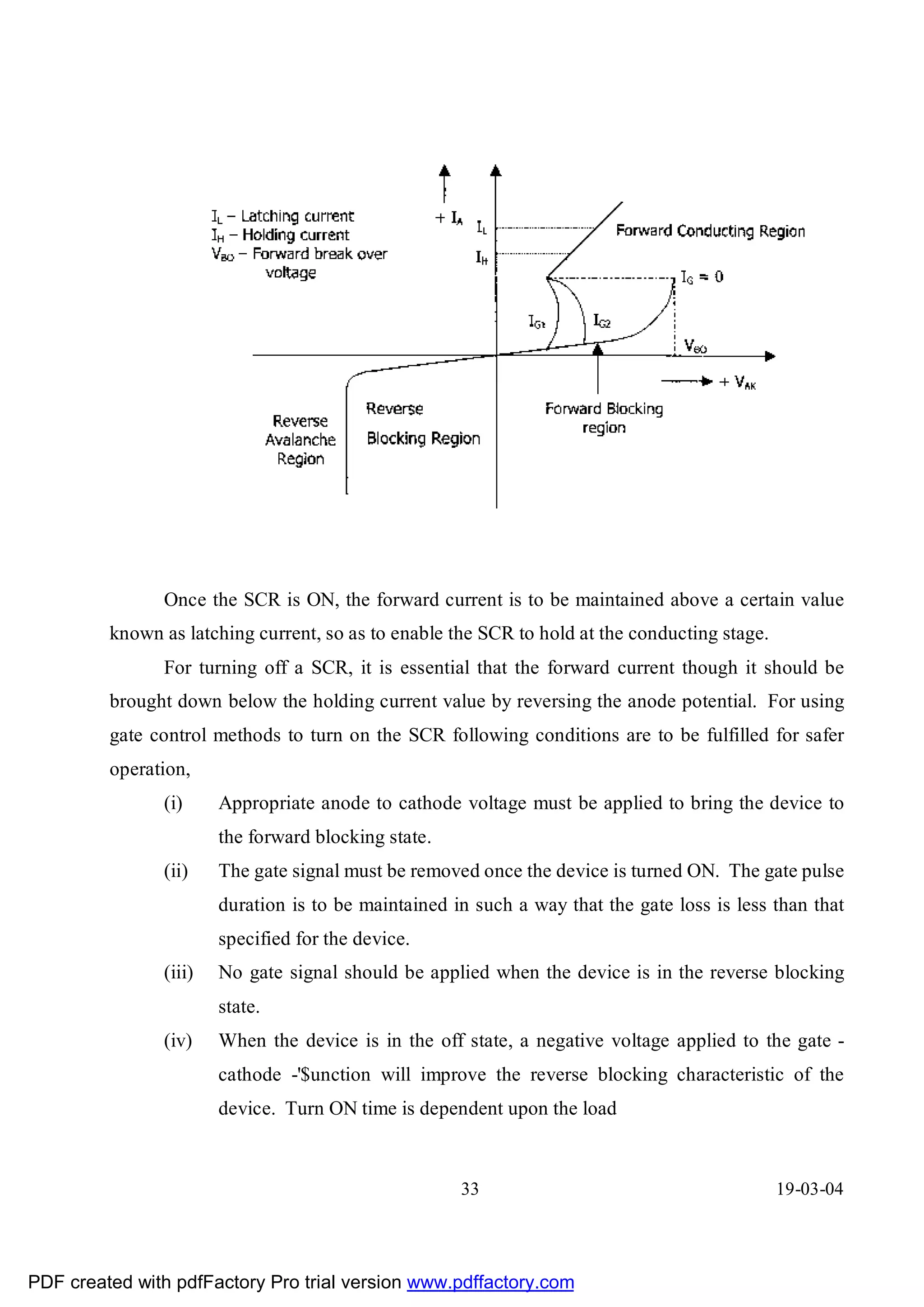
The SCR consists of four layers of P and N material and three junctions between
layers. This has got two blocking states. When the anode terminal is biased positively with
respect to the cathode, the junctions 31 and 33 are forward biased whereas 32 would be
reverse biased. So that current flow is blocked and the SCR is said to be in the forward
blocking state. Similarly, with a negative voltage applied to the anode with respect to
cathode, ]unction 31 and 33 are reverse biased and junction 32 is forward biased and the
device will not switch on. This state of the
31 19-03-04
PDF created with pdfFactory Pro trial version www.pdffactory.com
32.
SCR is calledas reverse blocking state or high impedance state. The SCR can be driven into
conduction state when blocking characteristic is erased and the SCR continues to conduct
until the current level fails below the certain lower value termed as holding current of the
SCR.
The SCR can be turned on by increasing the anode voltage sufficiently to exceed the
break over voltage, so that the reverse biased ]unction 32 breaks down because of large
voltage gradient across the depletion layers and the forward current increases. It is limited
only by the external resistance of the circuit. The most convenient method of switching the
SCR is by applying a positive trigger pulse to the gate of the SCR with lower positive anode
voltage than the break down voltage. This is known as the gate control.
32 19-03-04
PDF created with pdfFactory Pro trial version www.pdffactory.com
33.
Once the SCRis ON, the forward current is to be maintained above a certain value
known as latching current, so as to enable the SCR to hold at the conducting stage.
For turning off a SCR, it is essential that the forward current though it should be
brought down below the holding current value by reversing the anode potential. For using
gate control methods to turn on the SCR following conditions are to be fulfilled for safer
operation,
(i) Appropriate anode to cathode voltage must be applied to bring the device to
the forward blocking state.
(ii) The gate signal must be removed once the device is turned ON. The gate pulse
duration is to be maintained in such a way that the gate loss is less than that
specified for the device.
(iii) No gate signal should be applied when the device is in the reverse blocking
state.
(iv) When the device is in the off state, a negative voltage applied to the gate -
cathode -'$unction will improve the reverse blocking characteristic of the
device. Turn ON time is dependent upon the load
33 19-03-04
PDF created with pdfFactory Pro trial version www.pdffactory.com
34.
current and therate of rise of gate pulse. Turn off time depends on the recombination of
charges near junction 32. Some typical values of turn ON and OFF times are 1 to 4
microsecs and 10 to 250 microsecs respectively. For power frequency applications these
turn ON and OFF times does not pose any problems.
SELECTION PROCEDURE OF SCR BRIDGES FOR
STATIC EXCITATION SYSTEM
The following factors are taken into account,
(i) Peak inverse voltage
(ii) Junction temperature
(iii) dv/dt Rating
(iv) di/dt Rating
(v) Gate firing requirement
(vi) Current rating
PARALLEL OPERATION
For certain high current applicatio ns or for redundancy for the power stage
paralleling of the devices are required. For such cases, following points must be carefully
observed while designing the entire system.
(i) For paralleling, the connections which are done by bus bars and cables etc., are
to be kept symmetrical as far as practicable.
(H) Cooling for the devices are to be kept almost similar (i.e.) the positions and
type of mounting of the bridges and the cooling fans are to be,maintained
identical.
(iii) RC circuit should be so designed to keep the RC discharge current through the
device within the specified limit under all circumstances. In addition to the
above, precautions are to be taken to limit the rate of rise of RC discharge
current by providing decoupting reactors in series with the device.
34 19-03-04
PDF created with pdfFactory Pro trial version www.pdffactory.com
35.
(iv) The above series decoupling reactors with proper tolerances
also serve the purpose of reducing the missharing factor for the parallel
connected device. While designing this, missharing factor is to be taken into
account for the junction temperature calculation
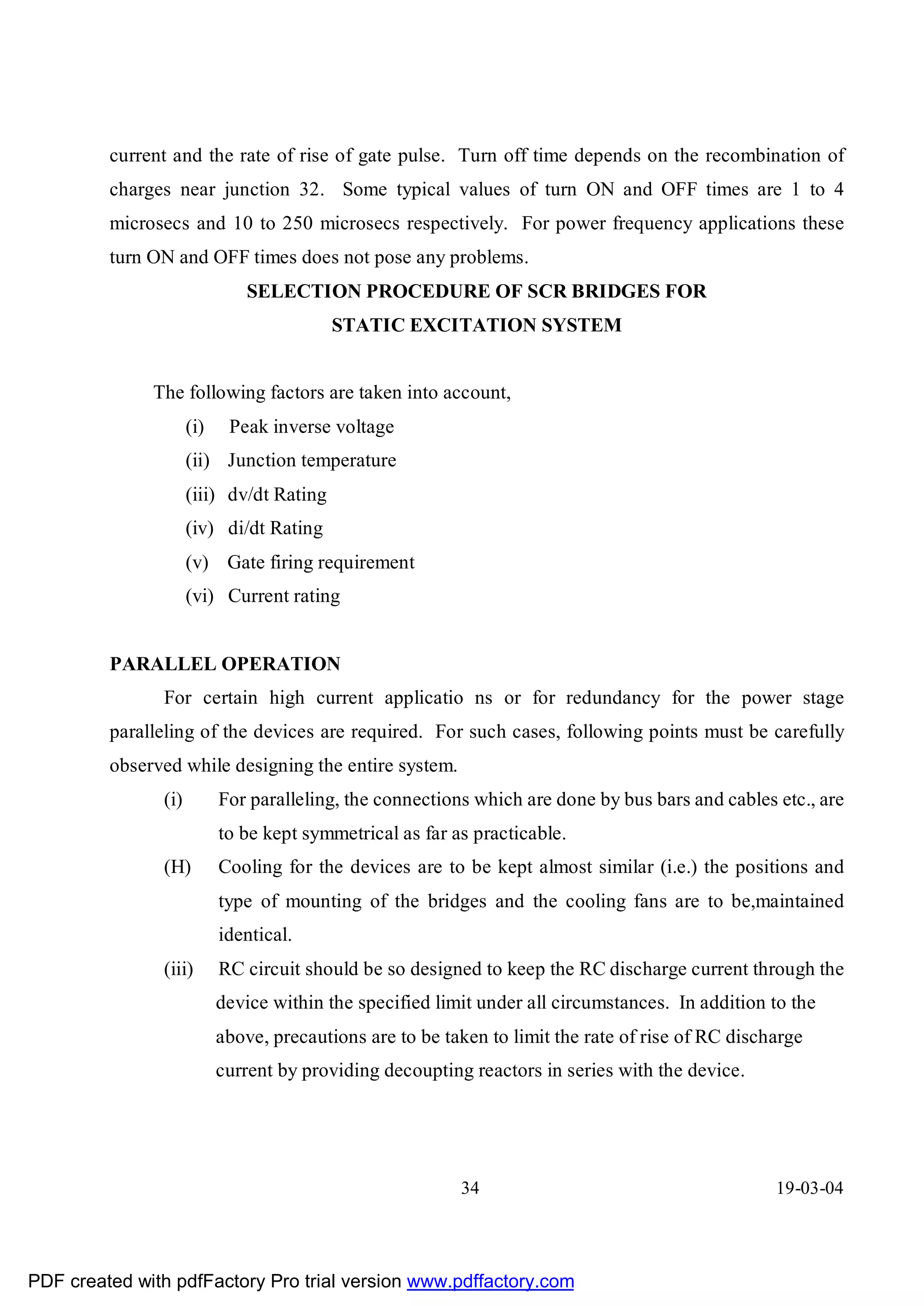
SNUBBER CIRCUIT
The R C Network across the thyristor is known as snubber circuit. The function of
snubber circuit is to limit the dv/dt with in maximum allowable rating. The snubber could be
polarized or unpolarized.
(i) Polarized:
A forward - polarized snubber is suitable when a thyristor (or) transistor is connected with
an antiparaltel diode. The resistor, R limits the forward dv/dt, and Rl limits the discharge
current of the capacitor when the device is turned ON.
35 19-03-04
PDF created with pdfFactory Pro trial version www.pdffactory.com
36.
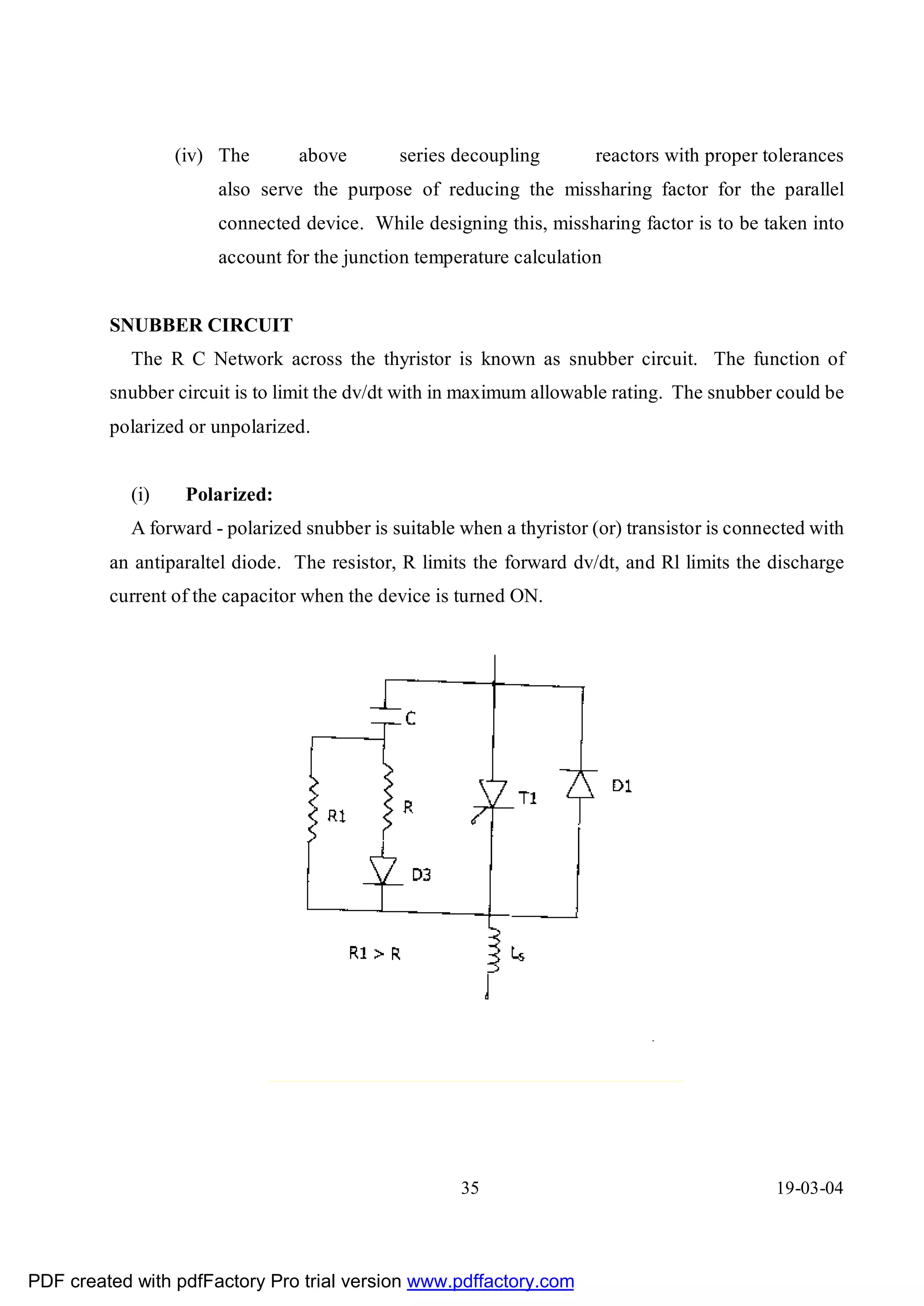
(ii) Reverse -Polarised:-
A reverse polarized snubber which limits the reverse dv/dt. Where Rl limits the
discharge current of the capacitor. The capacitor does not discharge through the device,
resulting in reduced losses in the device.
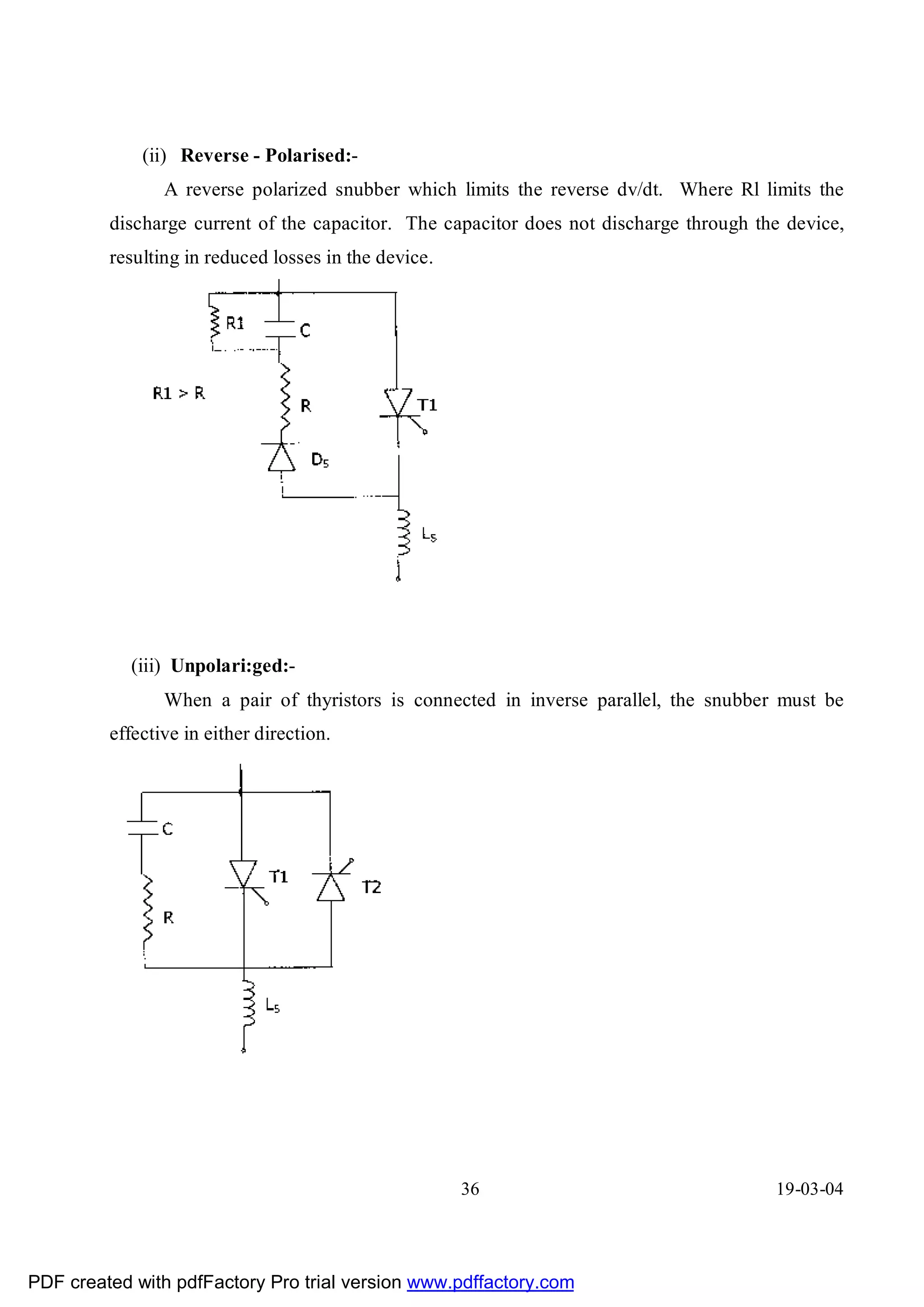
(iii) Unpolari:ged:-
When a pair of thyristors is connected in inverse parallel, the snubber must be
effective in either direction.
36 19-03-04
PDF created with pdfFactory Pro trial version www.pdffactory.com
37.
AVR - UN2010
The Automatic voltage regulator type UN 2010 is an electronic control module
specially designed for the voltage regulation of synchronous machines. It primarly consists
of an actual value converter, a control amplifier with PID characteristics which compares the
actual value with the set reference value and forms an output proportional to the difference.
The output of this module controls the gate control circuit UN 1001. The module does not
have an INBUILT power supply and derives its power from UN 2004, the pulse intermediate
stage and power supply unit. The AVR works on + 1SVDC supply.
The main features of this module are listed below
a) The AVR comprises of an input circuit which accepts 3 phase voltage signals of
11OVAC and 3 phase current signals of SA or 1A A.C. It is thus necessary to use
intermediate PT"s and CT"s to transform the generator voltage and current to the
above mentioned values. The module itself contains PT"s and CT"s with further step
down the signals to make them compatible with electronic circuit.
A CIRCUITARY is available in the module for adding the current signals
VECTORIALY to the voltage signals for providing compensation as a function of
active or reactive power flowing in the generator terminals.
b) An actual value converting circuit for converting the AC input signal to DC signal
with minimum ripple with the aid of filter network.
c) A reference value circuit using temperature compensated zener diodes. The output of
which is taken to an external potentiometer that provides 90-110 % range of operation
of the generator voltage.
37 19-03-04
PDF created with pdfFactory Pro trial version www.pdffactory.com
38.
d) A control amplifier which compares the reference and actual value and provides an
output proportional to the deviation. Apart from this, it has the facility to accept other
inputs for operation in conjunction with various limiters and power system stabilizer.
e) A voltage proportional to frequency network which reduces the excitation current
when frequency falls below the set level, thus keeping the air gap
flux constant. This prevents saturation of connected transformers and
possible over voltage.
38 19-03-04
PDF created with pdfFactory Pro trial version www.pdffactory.com
39.
LIMITERS IN STATICEXCITATION SYSTEM
LIMIT CONTROLLERS
With ever increasing size of generating units today, more stringent requirements have
to be met by excitation systems. Today, it is proven beyond doubt, that Static Excitation
assures, stable operation both under dynamic and transient conditions, Generators running in
parallel with the power net-work even under extreme conditions must remain in synchronism
without- the maximum load limit on it being exceeded and without the protective relays
operating. An automatic voltage regulator AVR alone cannot ensure this. Optimum
utilisation of the generator can be ensured only if the basic AVR is influenced by additional
signals to limit the under-excitation and over-excitation of the machine. Thus, limit
controllers working in conjunction with the AVR ensure :
a) Optimum utilisation of the machine.
b) Security of parallel operation etc.
Limit controllers simplify the job of the operating-staff and enables stable operation
close to the limiting values. With limit controllers in service, operational errors and faults in
the regulator lead only to the limit value control and not to disconnection.
It has to be understood that limit controllers however are not meant to replace the
protection system but they are only intended to prevent the protection system from operating
under extreme transient conditions.
PARAMETERS FOR LIMITATIONS:
Limiters, whenever they intervene, influence the voltage regulator suitable to bring
about a corresponding change in the excitation. The following are the parameters which are
to be limited.
1) Stator current under condition of over Excitation and under excitation
2) Rotor current
3) Rotor angle or the load angle
39 19-03-04
PDF created with pdfFactory Pro trial version www.pdffactory.com
40.
MECHANISM OF LIMITERINTERVENTION:
During over-excitation, the Rotor current and stator current limiters intervene to bring
about a reduction in excitation. On the otherhand during under excitation, limitation of rotor
angle and stator current influence to increase the excitation. Rotor and stator current limiters
must be designed to intervene after a certain delay so as to permit temporary over/ceiling
excitation, limiters do not impair the control behaviour of the AVR as over-excited condition
can exist in the event of load surge or because of short-lived faults in the power supply
network. The AVR reacts to a distance fault (say 3 phase short circuit) and commands
ceiling excitation to be applied, thereby increasing the synchronosing torque of the machine
and prevents it from losing synchronism. However, if the short circuit persists and has not
been cleared by system protection after a set time, delayed rotor current limiters comes into
operation preventing the generator and the excitation equipment from being subjected to
thermal over load. An identical situation prevails during sudden connection of load to the
system. The AVR enable short-time ceiling excitation to prevail so as to obtain lower
settling time.
The under-excited mode, the rotor angle limiter and stator current limiter must
intervene instantaneously to increase the excitation to prevent further increment in the rotor
angle.
In the under excited mode, stator current limiter is essentially used with multiple-pole
synchronous condensers which run at suitable level of excitation to increase the capacitive
absorption capability of the machine.
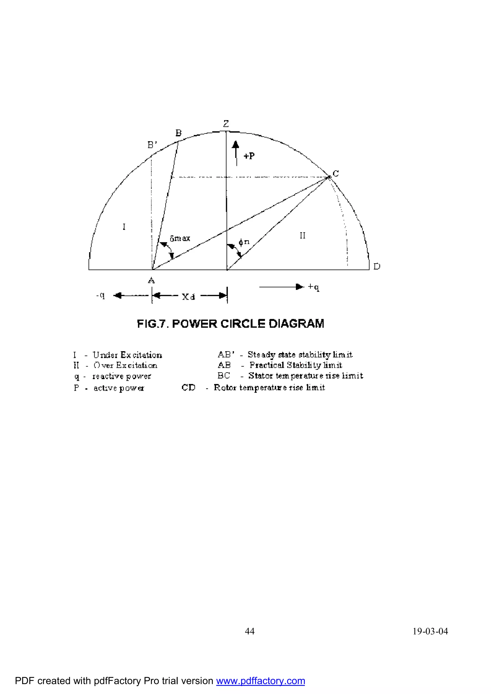
POWER DIAGRAM OF THE GENERATOR AND RANGE OF INFLUENCE OF
LIMIT CONTROLLERS
The operational limits of the sychronous machine are shown in the power circle
diagram. The application and range of influence of the limiters depends on the conditions in
the installation and the generator data. The possible zone of intervention of the limiterg is
marked in the power chart/power circle diagram. Fig.7
40 19-03-04
PDF created with pdfFactory Pro trial version www.pdffactory.com
41.
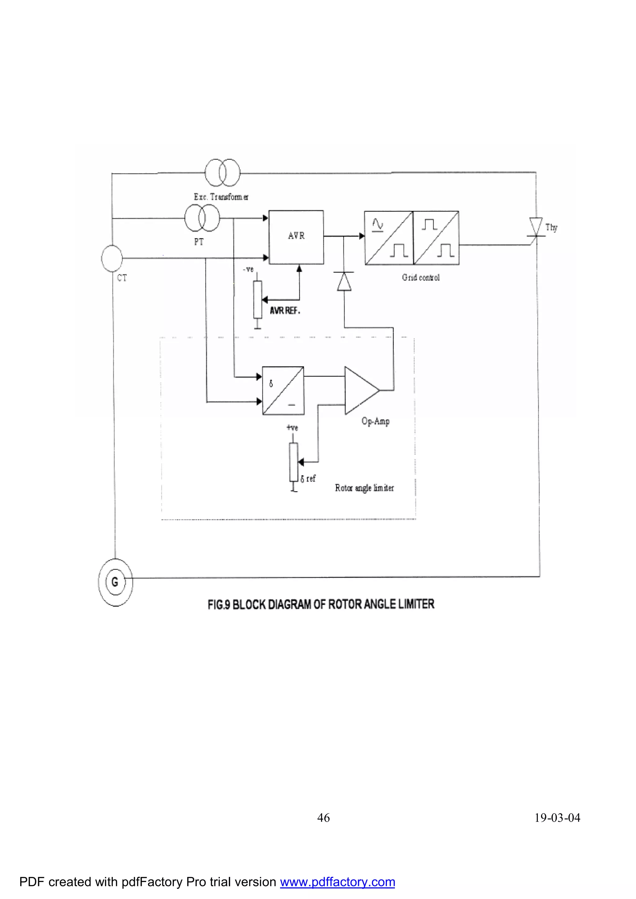
ROTOR ANGLE LIMITER:
Line AB represents the range of influence of the Rotor Angle, Limiter the maximum
angle of which has been taken as 85'. Although stable operation can be ensured even beyond
850 with the fast acting load angle limiter in action and achieve greater possible reactive
power absorption capability, the load angle is limited for practical purposes to 850 because
of the following considerations :
1) In the event of a short circuit in the systems,.the generators may accelerate owing to
the abrupt partial removal of the electrical load and as the turbine governor cannot act
fast, the rotor angle increases and the angle can become so large relative to the system
vector that the machine may fall out of step.
2) The excitation system (AVR) switches over to manual mode in the event of internal
faults in the auto-mode. Changeover to manual-mode signifies constant excitation
and hence a stable operation upto a maximum angle of 900 electrical only is possible.
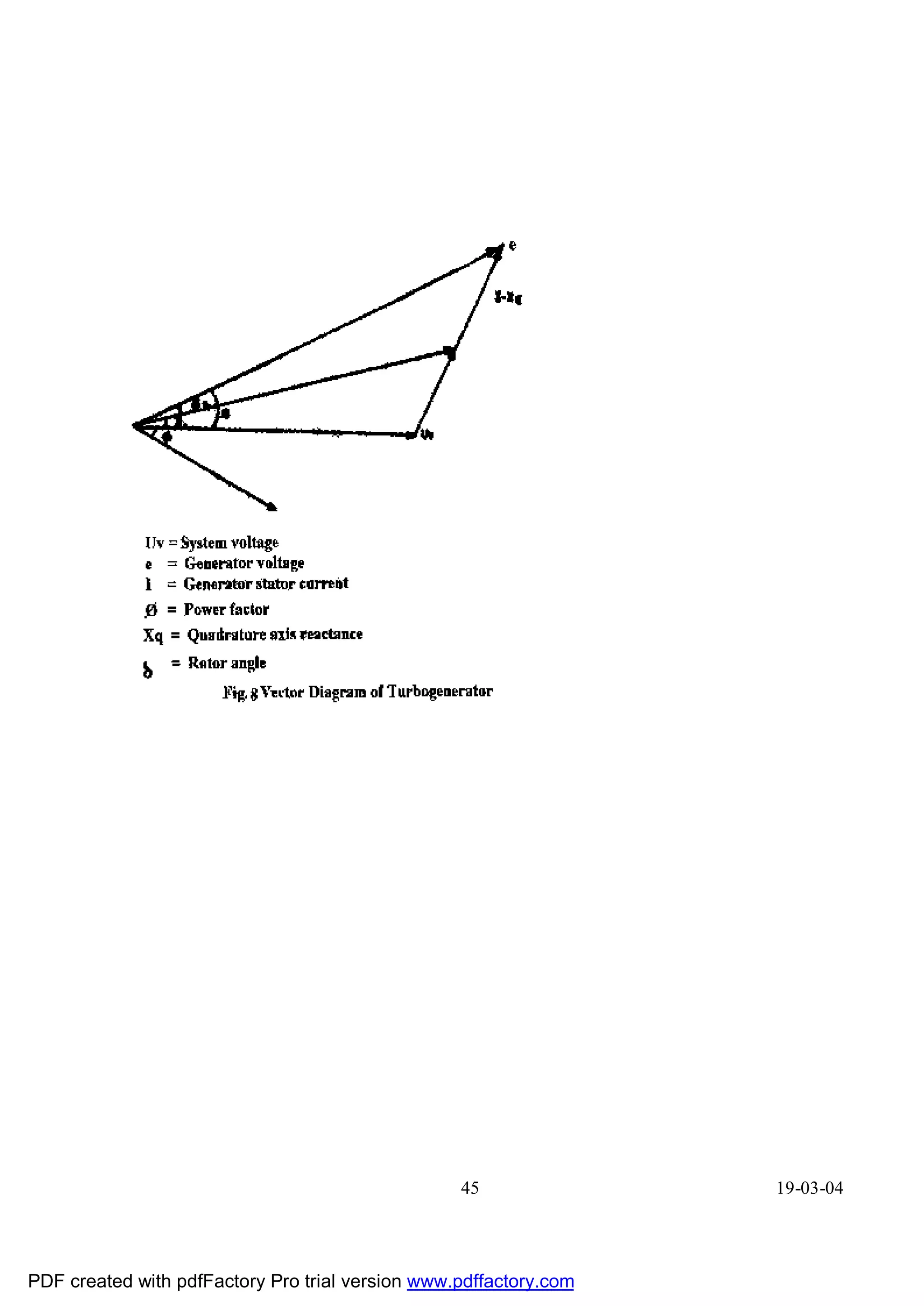
The rotor angle limiter limits the load angle of the machine to an acceptable
present value. The load angle is the electrical angle between the voltage vector of the system
and the vector of the machine voltage 'e' fig.8. The system vector is derived from the voltage
vector of the generator Uv by adding to it the voltage drop in reactances external to the
machine. This takes into account the transformers and transmission lines between the
generator and the system load centre. The rotor voltage is simulated adding the inductive
voltage drop in the machine IXq. The system voltage at the load centre is obtained by
subtracting Ixe drop (Reactance drop in the transmission line, transformers etc.) from the
generator terminal voltage.
The phase angle between 'e' and UN is converted into a proportional dc voltage. The
actual value is compared with an adjustable reference and fed to the input of an operational
amplifier. In case the angle exceeds the set value the output signal immediately takes over
the control of thyristor network to build up the generator air-gap flux fast enough to avoid
slipping. It stands to reason that the output of the limiter acts directly over AVR output to
avoid any loss of time due to filter time constants in the AVR. Fig.9 explains the operation
of Automatic Voltage regulator in conjection with rotor angle limiter.
41 19-03-04
PDF created with pdfFactory Pro trial version www.pdffactory.com
42.
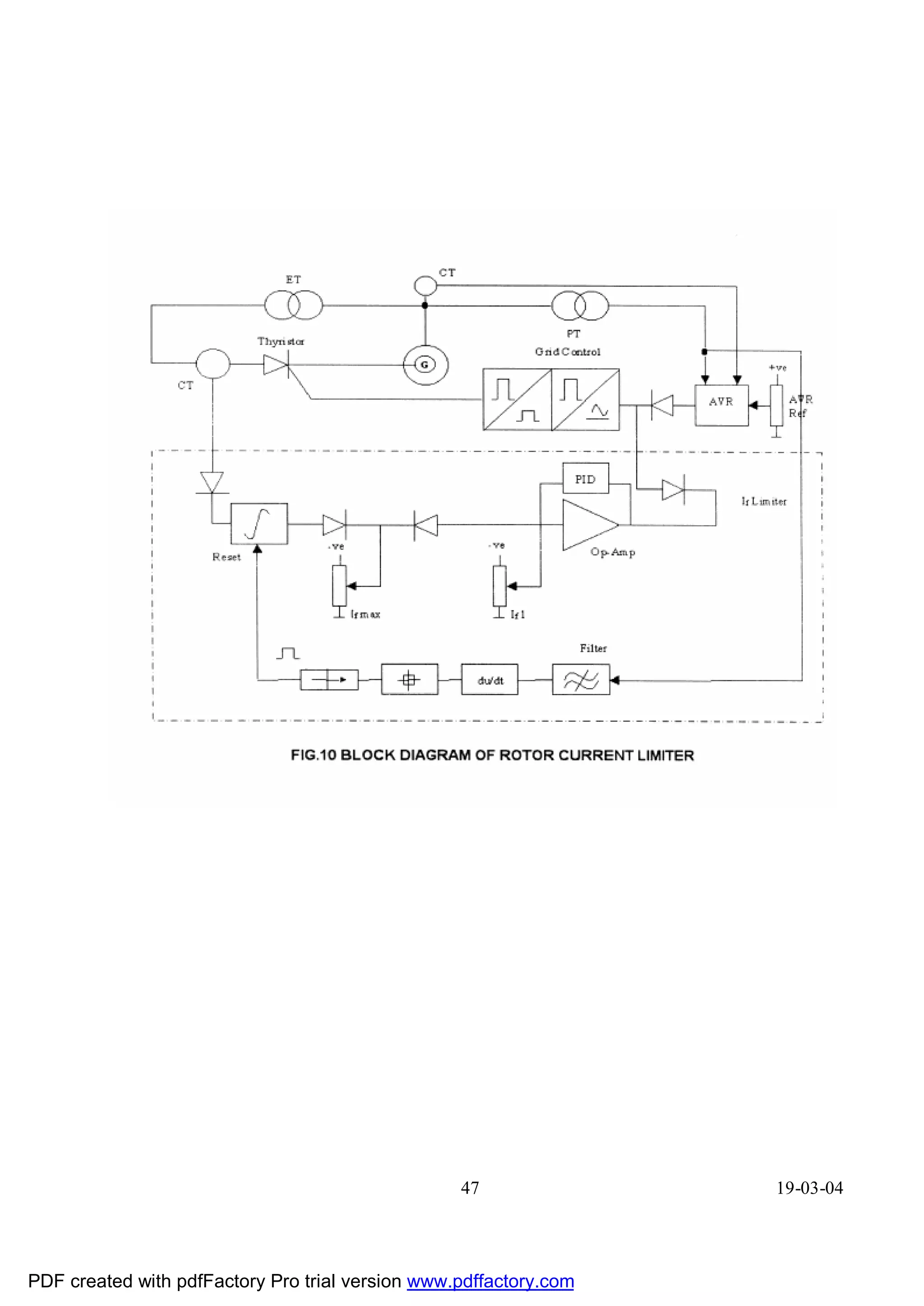
ROTOR CURRENT LIMITER:
The AVR drive the field or the thyristor network into overload for one or more of the
following reasons :
a) faulty handling b) system voltage reduction c) loss of sensing voltage to AVR and d)
failure within the controller. The excitation limiter must prevent this overload from
persisting. On the other hand, during dynamic disturbances in the system the excitation
should not be reduced at once, but ceiling excitation should be possible for a limited time.
The limiter can be operated in three different modes as explained below to cater the
above requirements.
i) Simple mode: In this mode the excitation current is limited to a preset maximum
value. The limiter intenienes with a time delay which is proportional to the magnitude of the
over load. Which the limiter in operation, the current is limited steadily to the rated value.
11) Mixed Mode: If during the above period of limitation, the generator voltage dips
steeply for any reason, the ceiling excitation limit is validated again. The ceiling excitation
current helps in increasing the short circuit current in the fault zones and hente aid selective
tripping of the faulted section.
iii) Switching mode : In the switching mode the excitation is limited to the thermal or
rated current value. Only in case of sharp dip in the machine voltage, the ceiling limit was
unable momentarily. The limit switches back to the rated value after the set time.
Figure-10 gives the block diagram of a rotor current limiter acting in conjunction with
AVR to limit the over excitation in the desired fashion.
42 19-03-04
PDF created with pdfFactory Pro trial version www.pdffactory.com
43.
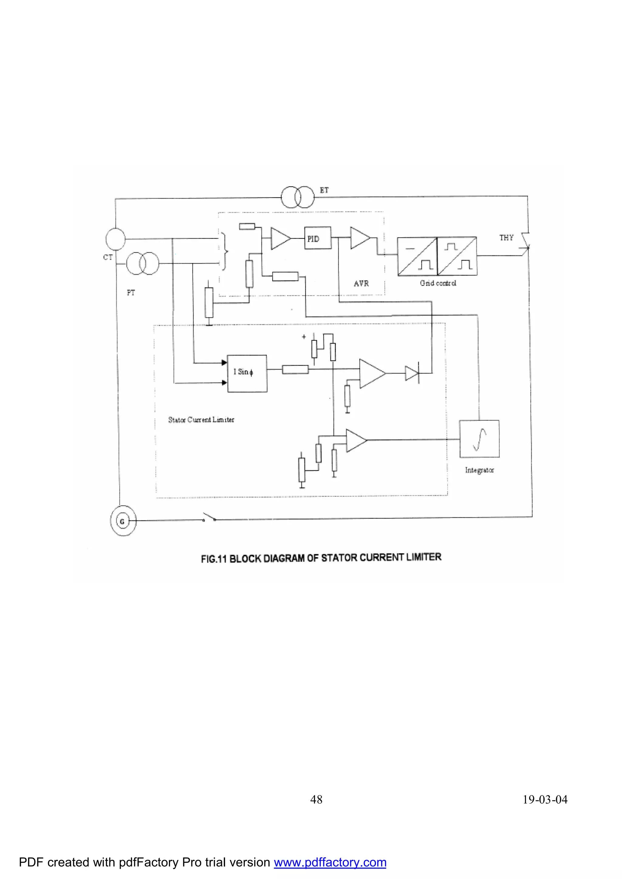
STATOR CURRENT LIMITER:
The stator current limiter has to influence the AVR differently depending on whether
the machine is over-excited or under-excited. The excitation current is to be suitably
reduced to limit the inductive stator current and is increased to limit the capacitive current.
The rotor angie limiter provides a more definite protection in preventing the machine from
failing out of step. Capacitive stator current limitation comes into play only with
synchronous condensers which are to some extent negatively excited with generators it
prevents excessive leading MVAR loading corresponding to any given MW load.
The generator stator current is converted into polarised dc signal +ve or -ve, depending
upon whether the machine is over-excited or under-excited. This voltage forms the actual
value for the controllers which process each of the bipolar signal independently. One of the
these controllers compare the capacitive stator current against its reference and acts directly
on the regulator via a de-coupling diode to increase the excitation. The action of second
controller which limits the inductive stator current is delayed by means of an integrator
before it influences the control input of the AVR so as to reduce the excitation. The time lag
offered is perfectly acceptable as far as stator overheating is concerned because of the
integrator time constant is set one order less than the stator thermal time constant. Fig. 11
shows an AVR operating in conjunction with a stator current limiter.
43 19-03-04
PDF created with pdfFactory Pro trial version www.pdffactory.com
44.
44 19-03-04
PDF created with pdfFactory Pro trial version www.pdffactory.com
45.
45 19-03-04
PDF created with pdfFactory Pro trial version www.pdffactory.com
46.
46 19-03-04
PDF created with pdfFactory Pro trial version www.pdffactory.com
47.
47 19-03-04
PDF created with pdfFactory Pro trial version www.pdffactory.com
48.
48 19-03-04
PDF created with pdfFactory Pro trial version www.pdffactory.com
49.
EXCITATION TRANSFORMER
INTRODUCTION:
Rectifier transformers directly connected to the generator terminals and feeding power
to the field of the machine via thyristor converters, plays an important role in an excitation
system and in turn power generation Reliability of this transformer has to be ensured in all
respects.
Importance of rectifier transformer has been realised ever-since the mercury arc
converters came into existence for important applications like large power drives and
excitation systems. A gradual development has taken place from oil filled transformers to
(resin) cast coil type transformers (dry type) for Excitation transformer.
Oil and clophen/Sovtol Iilied transformers are still adopted for large rating. However,
in urban areas and thickly populated cities where pollution control is a so to be thought of;
certain countries like West Germany have brought out regulation that oil immersed
transformers can be used only under special circumstances. Further, use of clophen/Sovtol
filled transformers has already been banned almost in all advanced countries because of
poisonous gases emanating in case of damages. Moreover, there has been constant rise in
price of oil in the international market, resulting in substantial increase in the total price of
transformer and its maintenance. Not only the above reasons but other hazards have led the
scientists to think of an alternate design which could gradually replace the oil and clophen/
Sovtot filled transformers. Accordingly vacuum impregnated dry type transformers were
taken up for large power and high voltage rating. The results were however not satisfactory
because of many limitations like effect of atmosphere, over voitages and the need for proper
drying out after long break in service. Therefore the need was felt to have better alternative
and cast resin moulding technique came into existence. The development of cast resin
transformers has led to the production of dry insulated type transformers upto 36 KV. These
transformers have not only been
49 19-03-04
PDF created with pdfFactory Pro trial version www.pdffactory.com
50.
found comparable tooil filled transformers but also proved their superiority in all respects.
These transformers are of class "F" insulation and indoor type.
VOLTAGE AND POWER RATING:
The selection of the secondary voltage of excitation transformer depends upon the
filed forcing voltage. The primary voltage is the same as that of generator terminal voltage.
Current rating is dependant on the maximum continuous current in the field winding.
Generally the power rating of the Excitation transformer used in Static Excitation System is
around 1 % of the rating of generator in MVA.
ENCLOSURE AND COOLING:
The enclosures are normally designed to ensure natural air cooling/Forced air cooling
to the transformers. These enclosures are made to IP20, IP21 or IP23 depending upon the
requirement. Forced cooling arrangement provides increase in rating by 40% than that with
natural air cooled transformer. Normally this arrangement is switched on during peak load
period or in summer to deliver more current from the same transformer. The description that
follows compares resin cast coil, dry type transformers with other transformers for various
characteristics.
SALIENT FEATURES
SHORT CIRCUIT PROOF:
The dynamic short circuit strength exceeds by far that of oil immersed transformers as
well as that of conventional dry type transformers. In the event of a short circuit the cast
resin transformer is not endangered mechanically, and only thermal damage can take place.
The high mechanical strength is achieved by casting the coils in epoxy resin with a fiber
glass filler to form a compact tubular spool. An insulation thickness of 1-2mm is quite
adequate to withstand the force that occur during operation.
50 19-03-04
PDF created with pdfFactory Pro trial version www.pdffactory.com
51.
HIGH OVER LOADCAPACITY:
In certain applications where rectifier transformer is subjected to intermittent loads
like rolling mill, furnace, traction and also in excitation duly high current increase, is
followed by low current demand. It results in the windings to be mechanically stressed to a
greater extent.
In cast resin transformers all the windings are cast and therefore no difficulties
concerning mechanical strength due to repeated overloads. Normally H.V. & L.V. Coils are
cast separately, all the forces appearing on one winding can be suitable absorbed by itself.
The resultant forces between primary and secondary windings can be made to absorb by
putting suitable support blocks between the coils and frame. Position of the support blocks
can be conveniently designed to reduce the forces to a lower value in contrast to
conventional type transformer.
Conventional type, wound coil transformers consume a considerable amount of
insulation material like paper which absorbs. the expansion of conductor and coils have to be
recompressed after certain periods', The cast coils being homogeneous, the coil structure
expands and contracts as a whole and the movement is taken care of by means of an elastic
support. Recompression of the coils is therefore not required.
In synthetic liquid cooled transformer there is a rated temperature jump between
winding and cooling liquid of the order of 20 to 250C with current density 3 to 4 A/Sq.mm.
In contrast, in these transformers with class F insulation the allowable temperature rise
between coil and air is of the order of 1000C with the same current density. This clearly
indicates the heating time constant of cast resin, normally 6-10 times, higher than that of oil
filled transformers.
RESISTT AGAINST TEMPERATURE FLUCTUATION:
The selected insulation material is fiber glass reinforced epoxy resin which has got
high tensile and bending strength. Therefore the transformer can withstand the wide range of
temperature fluctuations.
51 19-03-04
PDF created with pdfFactory Pro trial version www.pdffactory.com
52.
MOISTURE PROOF:
The cast resin coils are impregnated and cast under vacuum which ensures the
voidless embedding of all windings into a system of uniform glass fiber-epoxy laminate.
This process helps the coil to offer an increased protection against moisture.
Conventional dry type transformers are not moisture proof. The winding do absorb
humidity and there is danger of flashover once they are put in service after a long period.
IMMEDIATE SWITCH ON:
Because of the cast resin coil, the coils are homogeneously built in all respects. There
is no possibility of effect of moisture and ambient temperature fluctuations over coils. Under
such case the transformer can be directly switched on without predrying the same after long
interruption from service.
IMPULSE STRENGTH:
Impulse strength of these transformers is higher than that of conventional dry type
transformers and is comparable to that of oil cooled transformers according to any
international standard.
NON-INFLAMMAIBLE
Due to high quality of non-hydroscopic material, it has been proved that neither with
welding cutting torches nor with welding electric arc the cast coil resin could be induced to
burn and as such is almost non-inflammable.
PARTIAL DISCHARGE:
During operation, there is no partial discharges inside the winding, exceeding narrow
band 10 P.C. i.e. transformers are designed for long life.
52 19-03-04
PDF created with pdfFactory Pro trial version www.pdffactory.com
53.
COMPACT INSTALLATION:
Compared to oil and clophen/Sovtol filled transformers, the use of this type
transformer required less space, less weight and above all, the cost for the necessary erection
of catch-pits no longer exist. Because the cast resin coils are non-inflammable in nature a
sub-station consisting of a number of such transformers can be installed in the same building
near to the consumer end there by the power losses due to long distribution lines are also
avoided.
NO LEAKING:
Nothing can leak out from these transformers in contrast to clophen/sovtol and oil
filled transformers where there is a possibility of the liquid leaking. Therefore there is no
need to make catchpits at sites to avoid contamination to the ground water.
MAINTENANCE FREE:
Considering all above mentioned features it can be concluded that these transformers
are virtually free from maintenance.
- No re-adjustment of the winding and no re-tensioning of the individual coils are
required to maintain the short circuit strength.
- No control of oil is required
- No checking of electrical quality of used oil
- No dry out is necessary even after long interruption from use.
OVER CURRENT PROTECTION :
It is normally achieved with the help of current transformers mounted on each phase
on H.T. Side of excitation transformer. From current transformers current signals are given
to two over current relays, one is meant for instantaneous over current protection, another is
set for delayed over current protection. The latter is set to suit the field forcing requirements.
OVER TEMPERATURE PROTECTION:
It is achieved with the help of temperature sensors kept near the hot spot zone of the
L.V. Coils. The sensors have non-linear characteristic.
53 19-03-04
PDF created with pdfFactory Pro trial version www.pdffactory.com
54.
The resistance ofthe sensor is increased considerably after a certain temperature limit.
Normally two limits of over temperature are kept depending on the class of insulating
material used, one is the warning limit and another one for tripping of the equipment. Both
these limits are obtained by independent temperature sensor. The output of the sensors are
brought to the temperature monitoring equipment which signalises or calls for tripping.
CONNECTION ARRANGEMENT:
Normally the excitation transformer will have DyS vector group connection to
suppress harmonics. The angular displacement between HT and LT winding is 1500
Electrical degrees.
OPERATING CONDITION:
Inspite of all advantages of the cast coil resin transformers mentioned above, it is
recommended that this transformer should be mounted in an enclosure installed away from
water, oil leaking sources, away from sun rays and heat dissipating equipments. Care has to
be taken that sufficient free space all around is available to maintain the ambient temperature
and ventilation. The installation of the transformer has to be thought of in the beginning
itself to avoid dust. However, dust/carbon particles must be removed during periodical shut
downs. Normally this transformer is located just below the generator at exciter end either at
"O" meter level or at 4.Sm level.
CONCLUSION
In excitation systems, practically cast resin dry type transformers are used and there is no
necessity presently of using of oil cooled transformers with its inherent disadvantages of fire-
risk etc., as already mentioned. Further for indoor application it is preferable to use only dry
type transformers.
54 19-03-04
PDF created with pdfFactory Pro trial version www.pdffactory.com
55.
OPERATION OF STATICEXCITATION EQUIPMENT
Initially the main Circuit Breaker as well as Field Circuit Breaker is in open
condition. The signal lamp ""Excitation off' shows that the machine is not excited.
In order to start up the machine, machine should be first brought to nominal speed i.e.
3000 RPM. Pre-selection to be done for selecting the manual or auto control. The signal
lamps on the control unit indicate whether auto or manual control has been pre~selected.
As soon as the nominal speed is reached, the FFB (Field Flashing Breaker) & FB
(Field Breaker) to be closed. This is achieved through pressing the luminous button in the
cubicle or by a parallel connected push button (remote). Since the remanance voltage of the
machine is not sufficient to operate the regulator, initially suitable station A.C. voltage via
full wave bridge rectifier or suitable DC voltage from station batteries to be supplied through
Field Flashing Breaker. The machine voltage rises to 30% , then the electronic regulation
start functioning by getting the released pulses, which were blocked till then. The blocking
of pulses is cancelled through voltage relay and regulator takes over the function of
regulating the machine voltage.
At 70% of the machine voltage, the field flashing (FF) supply is switched off with the
help of FFB. Till 70% of Machine voltage both Auxiliary supply and main supply are
available for excitation. However for avoiding re-entry of supply to FF unit, blocking diodes
are provided both in A/C & DC supply circuit. From 70% of machine voltage the total
requirement of Excitation current is taken through SCR. The reference value for auto control
can be set between 90% & 110% of nominal voltage. For manual control variation of
voltage can be done through Potentiometer from 0 to 90% or 0 to 110% as per the
requirement.
55 19-03-04
PDF created with pdfFactory Pro trial version www.pdffactory.com
56.
The power circuitof Static Excitation station consist of the following
1) Excitation Transformer
2) Thyristor Bridges
3) FFB, FB etc. (Field Flashing Breaker, Field Breaker)
The electronic regulation cubicle consists of various unitrols (The unitrots are
modular type & each unitrol is assigned with specific no. for identification).
The following are some of the module/unitrol used in regulation cubicle.
UNITROLS - UN
UN 1024 FIELD CURRENT LIMITER
1022 STATOR CURRENT LIMITER
1043 ROTOR ANGLE LIMITER
2010 A.V.R
1001 GATE CONTROL UNIT
2004 POWER SUPPLY & AMPLIFIERS
2001 FINAL PULSE AMPLIFIER
UN 0053 PULSE SUPERVISION UNIT
0040 PULSE COMPARATOR UNIT
0516 SUPPLY SUPERVISION UNIT
UN 0510 FOLLOW UP MODULE
1011 COMPARATOR UNIT
007 POTENTIO METER
0014 TRANSDUCER
0030 POWER TRANSDUCER (ACTUAL POWER
MEASUREMENT UNIT)
0072 SUPERVISION & SUMMING UP UNIT
0517 SUPPLY SUPERVISION UNIT
KT 7480 DCJDC CONVERTOR 220/48V
UN 7467 48124V
56 19-03-04
PDF created with pdfFactory Pro trial version www.pdffactory.com
57.
SALIENT FEATURES OFSTATIC EXCITATION SYSTEM
MERIT OF STATIC EXCITATION SYSTEM
I PERFORMANCE
1) Faster Response in voltage & Reactive Power Control
2) Higher Accuracies of Voltage control
3) Faster discharge of field energy with inversion of thyristor bridge output
4) Provision of limiters & stabilizing equipment help to improve dynamic & transient
stability
5) Largely independent of variation in the excitation supply voltage & frequency
II OPERATIONIMAINTENANCE
1) Redundancies in different Circuits increase reliability and availability
2) Adequate monitoring facilities aid fault finding & reduce down time
3) Absence of rotating parts enables less maintenance
4) Lower SCR value for larger generators (Reduces weight/compact in size & cost)
III GENERAL
1) Uprating of the machine can be done by adding additional power circuits/adding more
redundancies
2) Location of the equipment can be planned independent of the machine thereby
increasing the flexibility in the plant layout
3) Retrofitting of Static Excitation Equipment for old slow acting exciter
4) Length of the machine shorter when compare to other excitation equipment
57 19-03-04
PDF created with pdfFactory Pro trial version www.pdffactory.com
58.
IV) PURPOSEIFUNCTION OF STATIC EXCITATION SYSTEM
1) Regulate stator voltage (Terminal V) of the machine
2) Meet excitation power requirements under all normal operating conditions
3) Enable maximum utilisation of machine capability
4) Guard the machine against inadvertent tripping during transients
5) Improve dynamic and transient stability thereby increasing plant/machine availability
6) Regulate MVAR loading with in iirffits
7) Flexibility in control (Auto/manual)
8) Fast acting to meet demand during dynamic performance of Generator
IMPORTANT FEATURES IN STATIC EXCITATION SYSTEM
1) Dual channel (Auto and Manual)
2) Limiters
3) Slip stabilisation
4) Redundancy in thyristor bridge
5) Part load operation with bridge failure
6) Manual follow up control
7) Non-linear field discharge'resistor
8) Maintenance free dry cast coil excitation Transformer
9) Isolation of faculty thyristor bridge for repairs
10) Withdrawable type of power modules
11) Stabilised DC power supply units for a very wide variation of input AC voltage
12) Control voltage standardised with DCJDC converters (48V/24V)
13) Min. & Max. Excitation limiters.
14) Volts/hertz. limiter (WF-Over fluxing Protection)
15) OVP
58 19-03-04
PDF created with pdfFactory Pro trial version www.pdffactory.com
59.
CONCLUSION
1. Power and control supply is from generator itself through Excitation Transformer.
2. Four or more independent thyristor bridges (6 in each bridge). Three are enough for
full load operation.
3. Four or more cooling fans for forced cooling of thyristors (Thyristors protected by
interlock Circuit such that upon interruption in (AFR) Cooling the firing is cut off
with in 20 seconds).
4. Thyristors protected by fast acting fuses (FSM). The failure of fuses is signaled and
concerned bridge is isolated
5. During normal operation it is possible to work on any thyristor/Fuse etc. by isolating
it on AC & DC sides
6. For 'Initial Excitation field flashing circuit is provided. AC or DC supply can be used.
Circuit cuts off automatically when 70% Generator voltage (Stator) is reached.
7. Field interruption by double pole, double break field breaker with FDR in Circuit.
8. OVP - Over voltage shorting switch is provided across the field circuit to protect it
against heavy over voitages. The switch cuts in a resistor and also gives a trip order
9. The voltage regulator is of two channels have independent power supplies, grid
control units and first stage amplifiers. In auto control Generator Voltage is sensed
and maintained while on manual control a steady output depending on hand set
reference is maintained.
10. Thyristor firing pulses are generated as per control voltage in GCU (1001). These
pulses are blocked when Generator Voltage is less than 30% of rated value. They are
shifted inverter operation region when the field breaker trips.
59 19-03-04
PDF created with pdfFactory Pro trial version www.pdffactory.com
60.
11. These pulsesare amplified in pulse amplified in pulse amplifier cum PS unit
(2004). Here auto/manual pulses are released as per the channel in operation (for
channel not in service pulses are blocked)
12. Amplified pulses are led to final stage amplifier and from there to the
thyristor via pulse transformers. Each bridge has one final stage pulse amplifier. The
pulses are blocked here when any defects arises with in the bridge like fuse failure or
interruption in cooling circuit etc.
13. An earth fault relay gives an alarm when the insulation resistance of the field circuit
goes below preset value.
14. Stator current limiter, Rotor current limiter, Rotor angle limiter units are provided to
ensure that the Generator is operated within the capability curve while working at limit
conditions for effective utilisation.
15. Slip stabiliser unit helps to stabilise the power swings and thus prevents the generator
from tripping.
16. Over current relays and temperature supervision protects the rectifier transformer.
60 19-03-04
PDF created with pdfFactory Pro trial version www.pdffactory.com
61.
61 19-03-04
PDF created with pdfFactory Pro trial version www.pdffactory.com
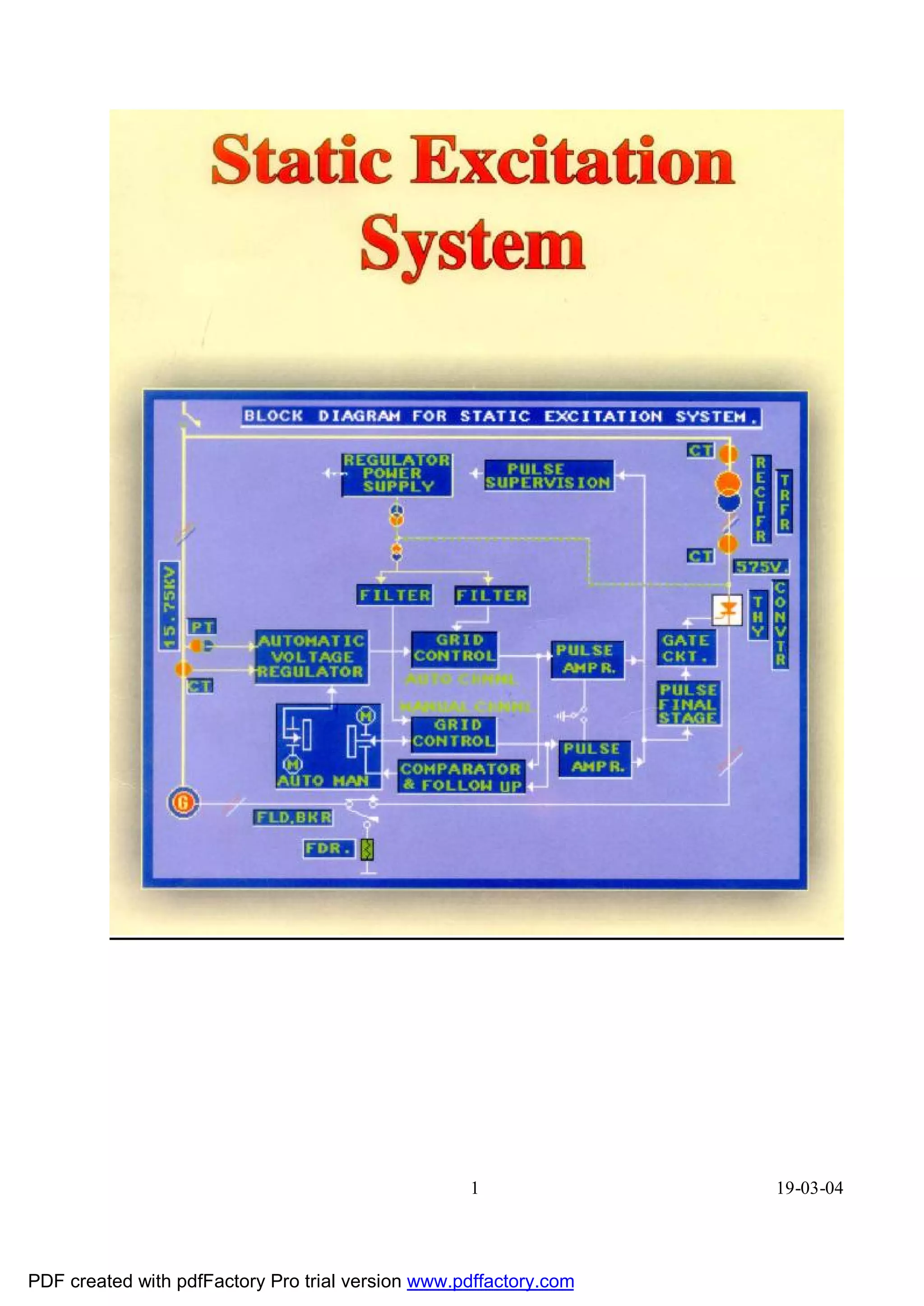
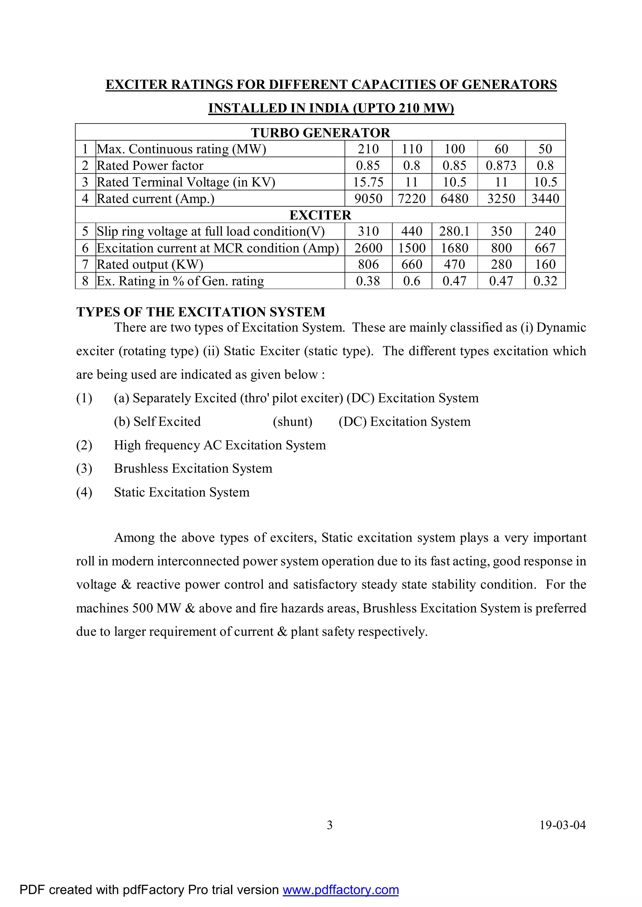
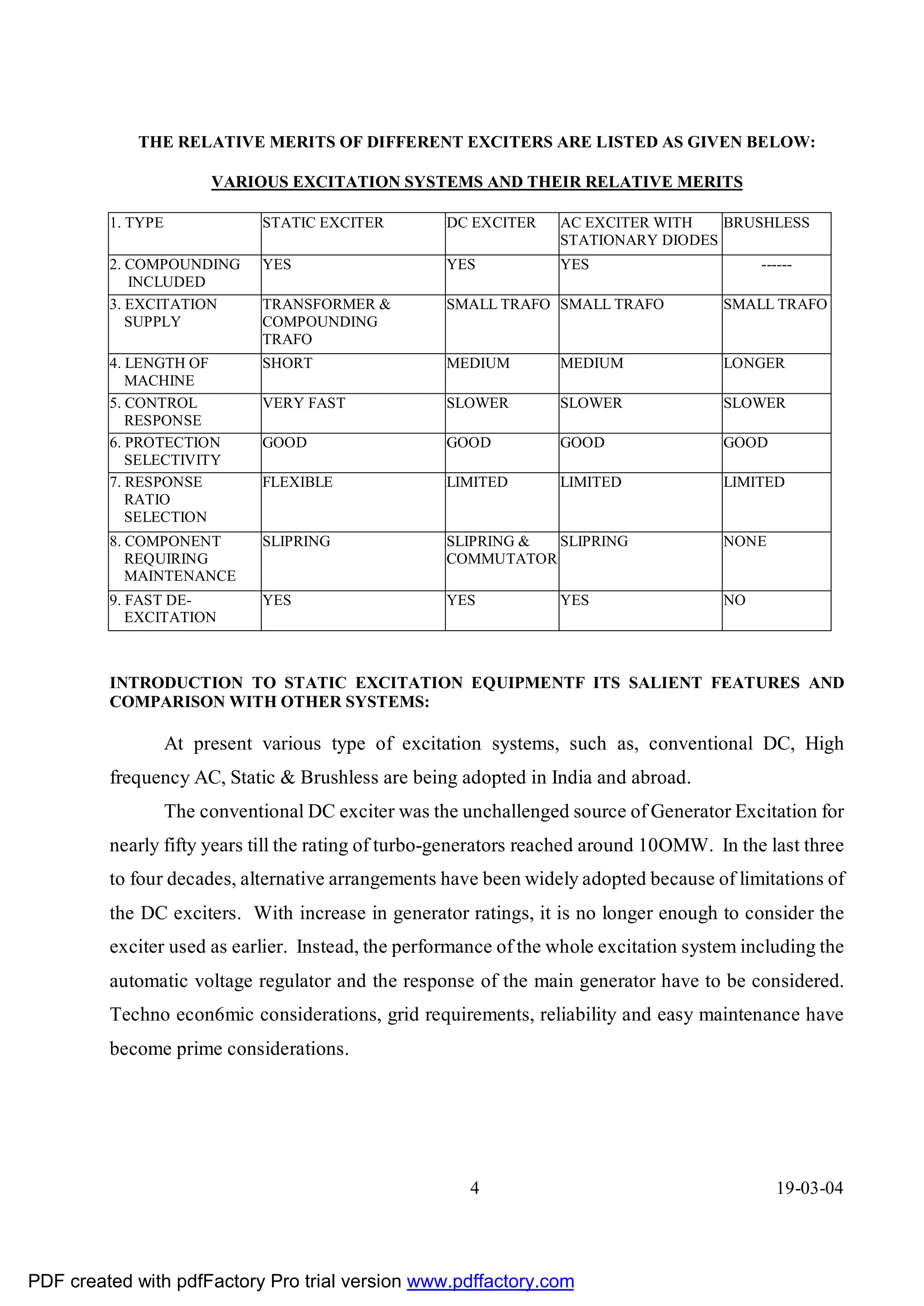
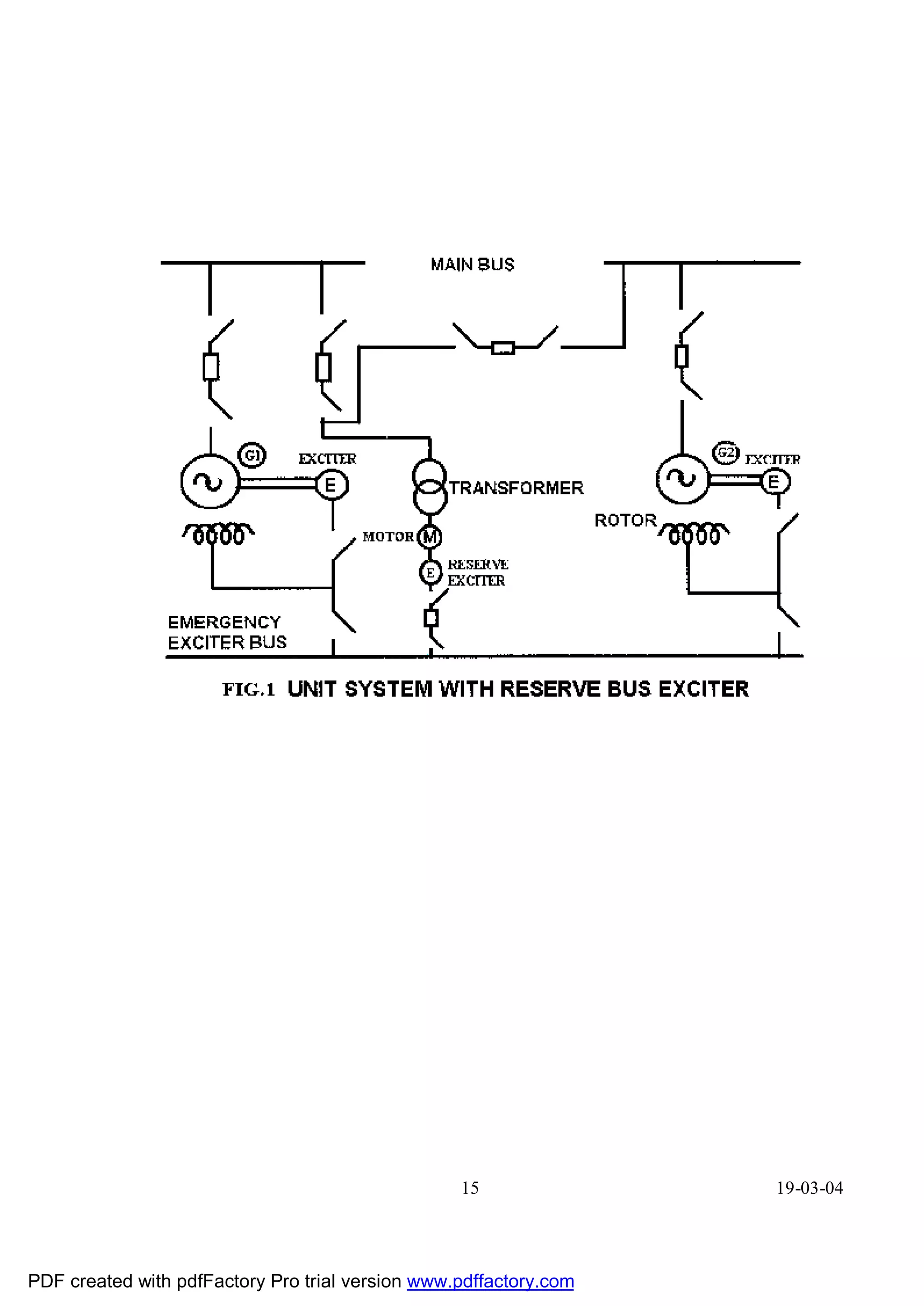
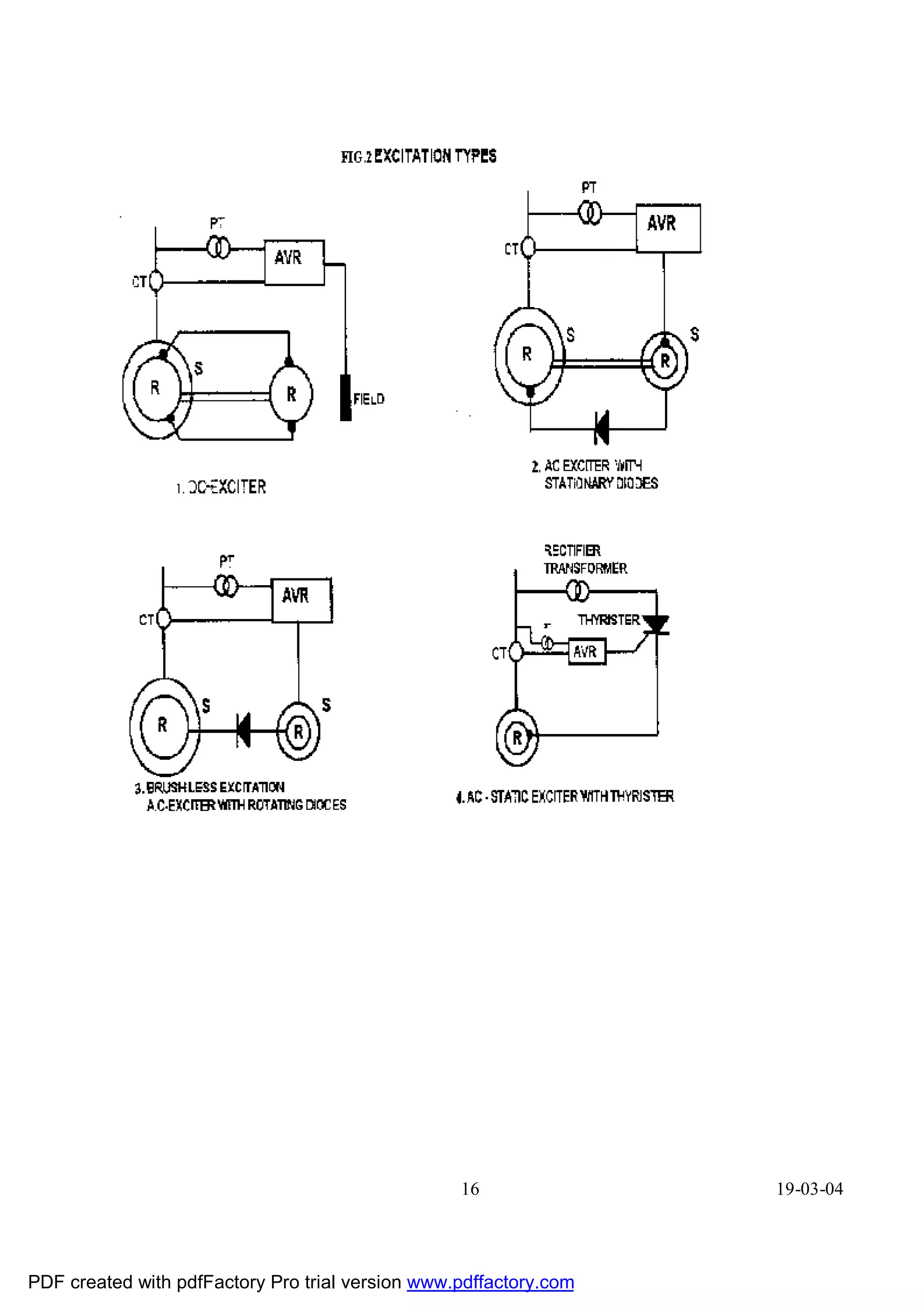
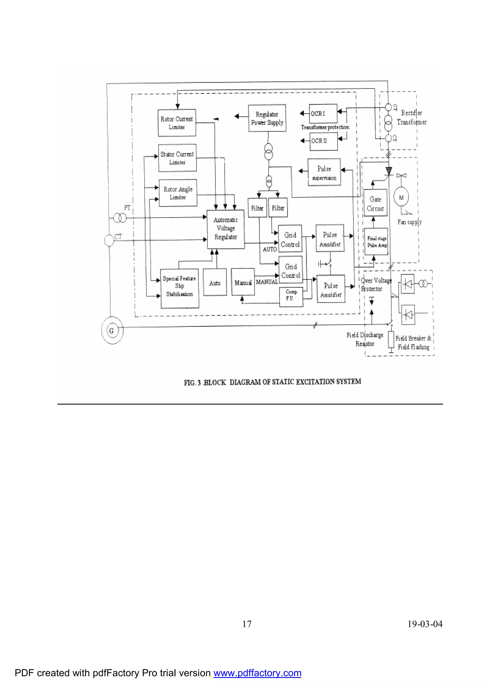

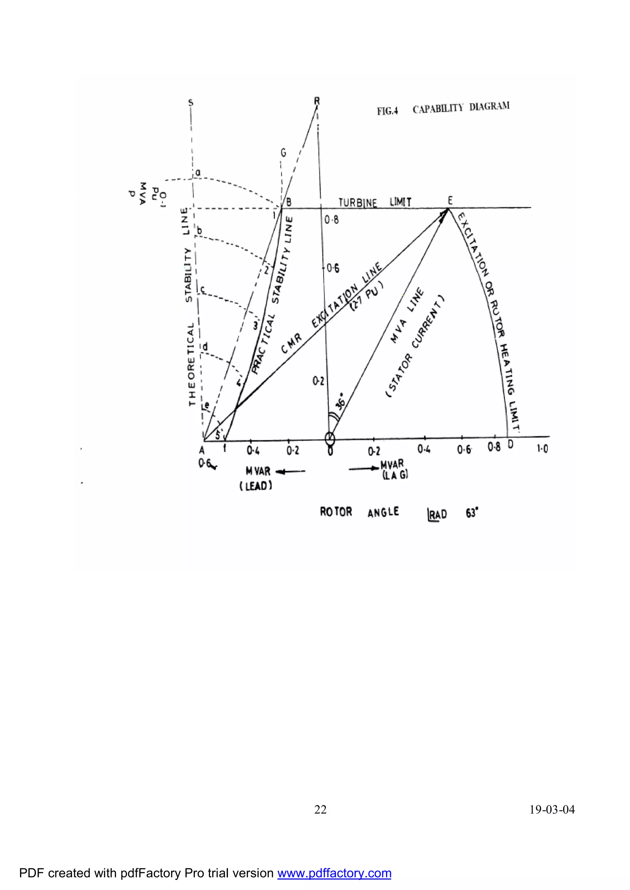


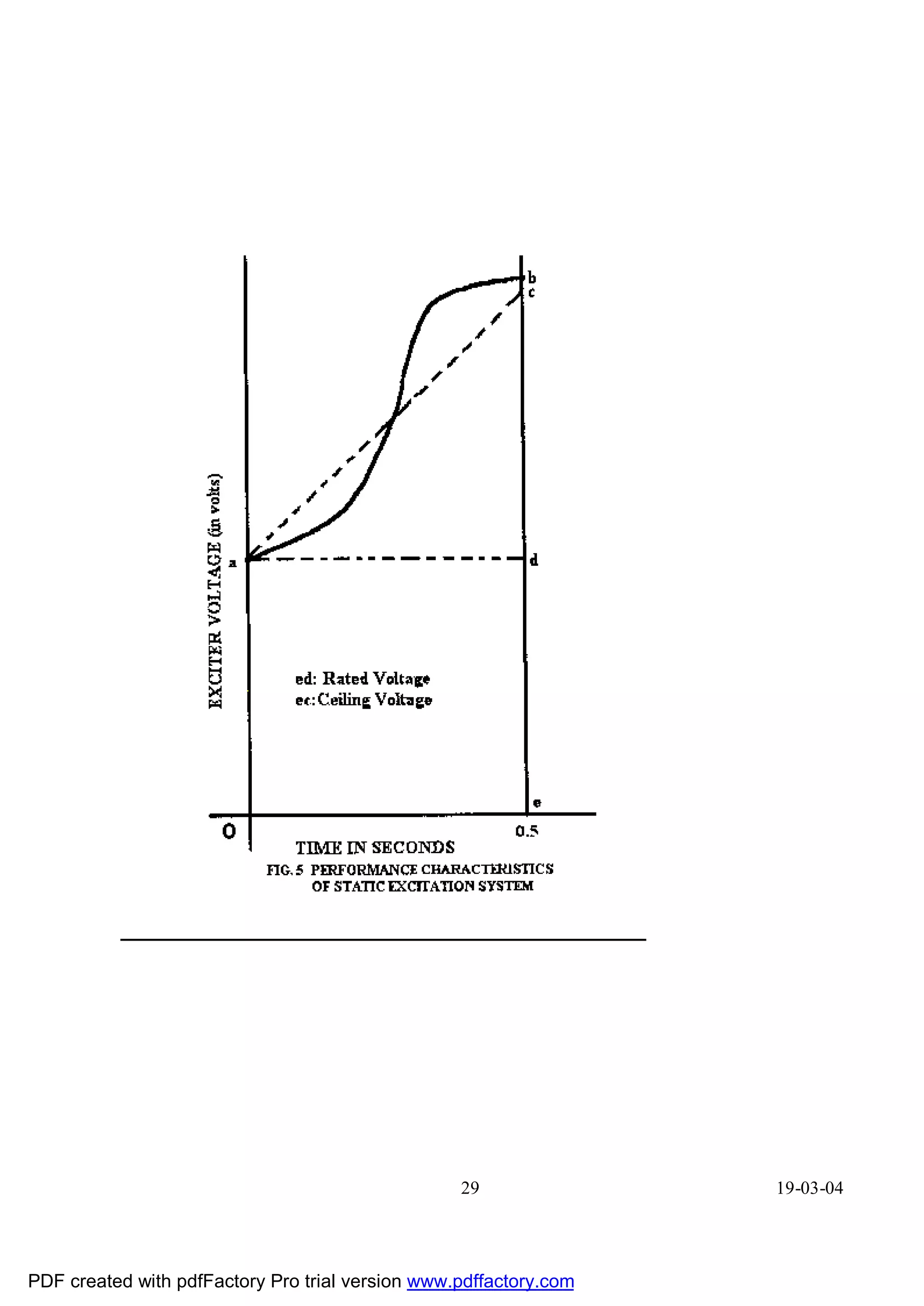
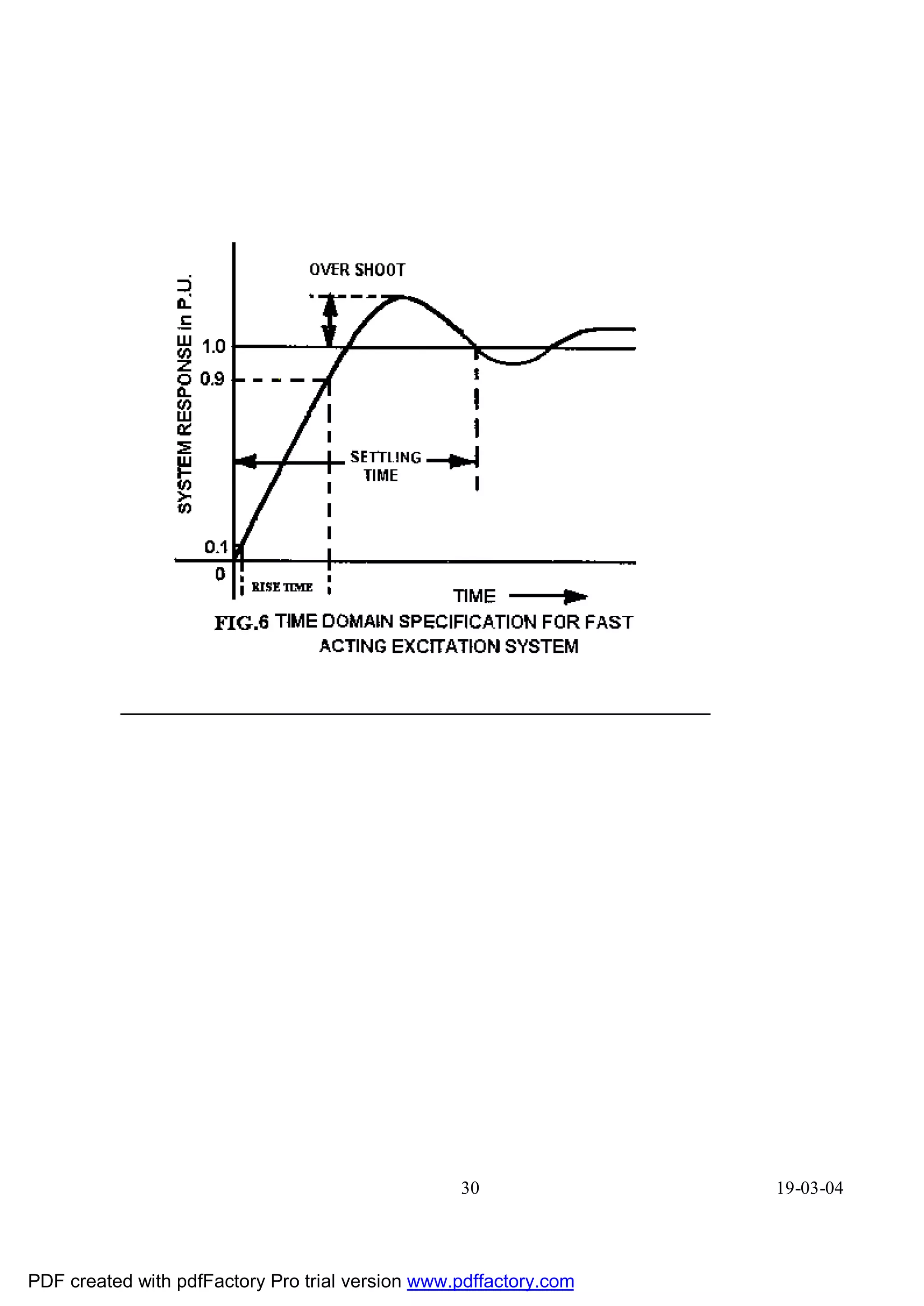
![THYRISTOR - CHARACTERISTICS & ITS APPLICATION IN STATIC
EXCITATION SYSTEM
INTRODUCTION
In the latest trend of excitation system neither the rheostatic mode of excitation control
nor the magnetic amplifier type of control system is used as these are sluggish in action and
have an inherent dead band of operation because of their low loop gains.
The use of SCRs at the power stage for the excitation system with voltage regulator
control the response of the system is much faster than the conventional ones. The modern
excitation systems incorporating SCRs at their power stage have a very low dead band.
SYSTEM DESCRIPTION
The excitation power being fed from the generator terminals or auxiliary supply
through normally a stepdown transformer and then to the input of the SCRs bridge. The
voltage regulator having closed loop control compares the actual terminal voltage of machine
with that of the set reference value and forms an error signal, which controls the firing angle
of the thyristor bridge. Subsequently, the variable controlled DC voltage is applied to the
field of the generator through a field breaker. The SCRs bridge forms an important integral
part of the excitation system by providing an accurate and fast field DC voltage control.
THEORY OF DEVICE
The SCR consists of four layers of P and N material and three junctions between
layers. This has got two blocking states. When the anode terminal is biased positively with
respect to the cathode, the junctions 31 and 33 are forward biased whereas 32 would be
reverse biased. So that current flow is blocked and the SCR is said to be in the forward
blocking state. Similarly, with a negative voltage applied to the anode with respect to
cathode, ]unction 31 and 33 are reverse biased and junction 32 is forward biased and the
device will not switch on. This state of the
31 19-03-04
PDF created with pdfFactory Pro trial version www.pdffactory.com](https://image.slidesharecdn.com/static-excitation-system-130130015122-phpapp01/75/Static-excitation-system-31-2048.jpg)
![SCR is called as reverse blocking state or high impedance state. The SCR can be driven into
conduction state when blocking characteristic is erased and the SCR continues to conduct
until the current level fails below the certain lower value termed as holding current of the
SCR.
The SCR can be turned on by increasing the anode voltage sufficiently to exceed the
break over voltage, so that the reverse biased ]unction 32 breaks down because of large
voltage gradient across the depletion layers and the forward current increases. It is limited
only by the external resistance of the circuit. The most convenient method of switching the
SCR is by applying a positive trigger pulse to the gate of the SCR with lower positive anode
voltage than the break down voltage. This is known as the gate control.
32 19-03-04
PDF created with pdfFactory Pro trial version www.pdffactory.com](https://image.slidesharecdn.com/static-excitation-system-130130015122-phpapp01/75/Static-excitation-system-32-2048.jpg)