Downloaded 206 times
![LITERATURE REVIEW
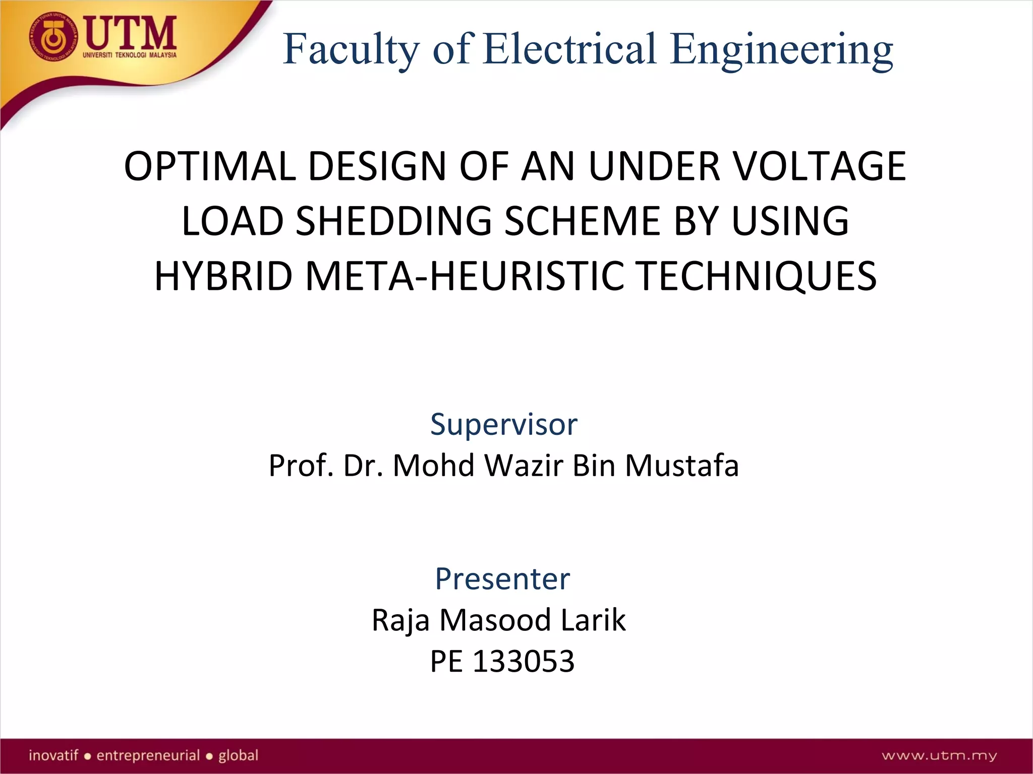
S.No Author Technique Strength Weaknesses Journals/Yrs
of Publish
1 Abbas Ketabi
[20]
A sensitivity-based
method for UFLS
Hybrid and Multi area
Power Systems
Voltage stability is
ignored
IEEE Trans.on
smart grid 2015
2 Ahmad Ahmadi
[24]
New Integer-value
modeling
Minimizing total
amount of load shed and
the amount of
interruption cost
Hybrid Power
system not
considered
Journal
ELSEVIER
2014
3 M.M Hosseini
[23]
A techno economic multi-
objective optimization
Consider social welfare
and smart market
Hybrid Power
system not
considered
Journal
ELSEVIER
2013
4 Alireza
Saffarian
[22]
Designing the 3-D
combinational Load
shedding method
adaptive combinational
LS methods are
proposed
Traditional LS
schemes are not
capable of dealing
with combined
instabilities
IEEE Trans. On
power systems,
2011
5 Urban Rudez
[21]
Frequency of center of
inertia (COI) in adaptive
LS schemes
Only under frequency
load shedding
considered
under Voltage
load shedding not
considered
IEEE Trans. On
power systems,
2011
Summary of Related Work](https://image.slidesharecdn.com/undervoltageloadshedding-150615035142-lva1-app6892/75/Under-voltage-load-shedding-7-2048.jpg)
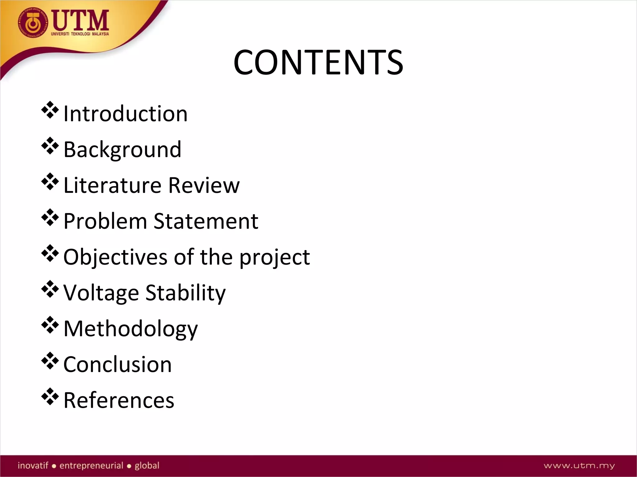
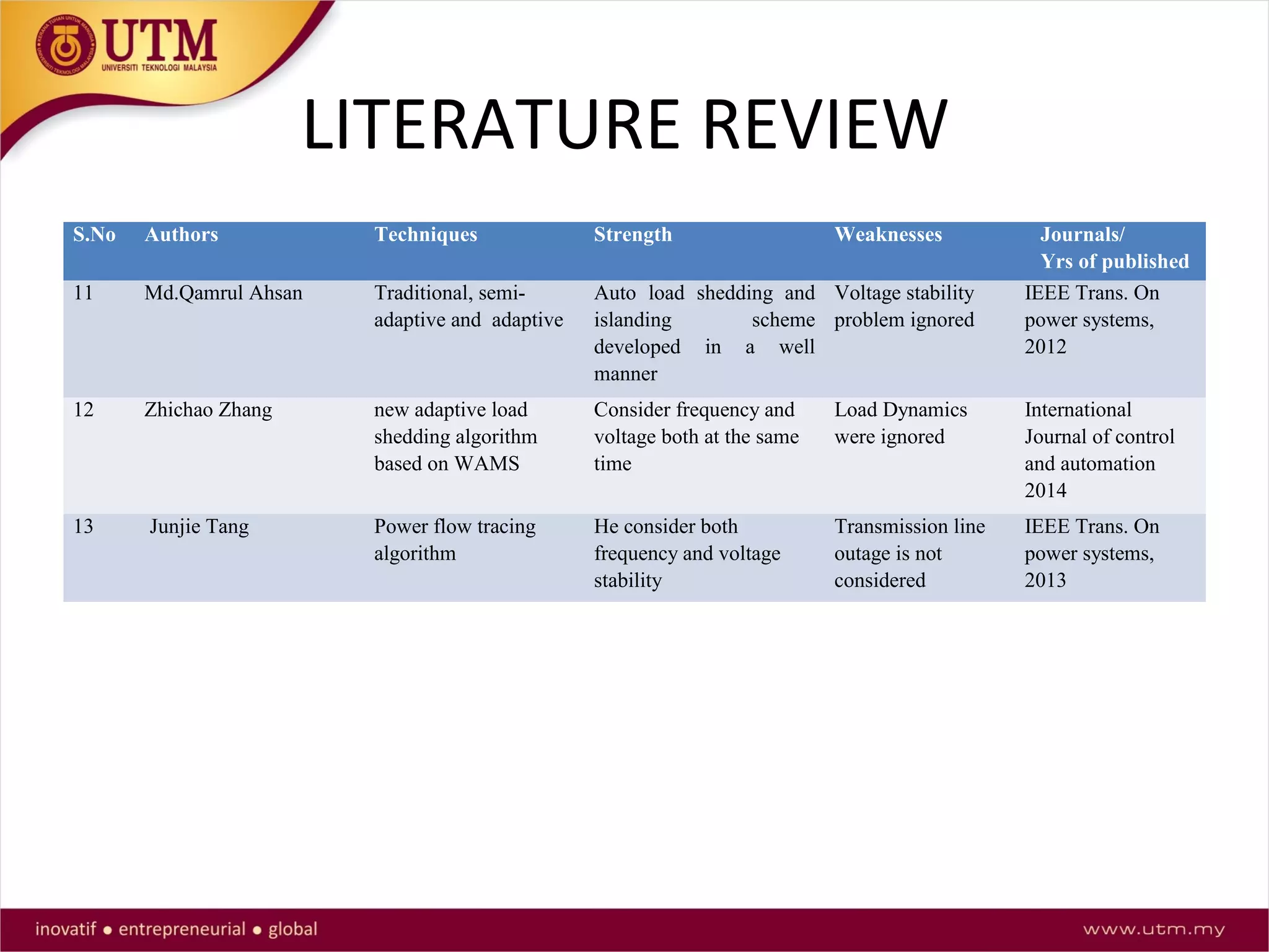
![LITERATURE REVIEW
S.No Authors Techniques Strength Weaknesses Journals/
Yrs of published
6 M.H.A Hamid UVLS based on
voltage stability
index
Dynamic simulation DG’s were not
considered
IEEE innovative
Smart grid
technologies
Proceedings 2014
7 Arief ardiaty Trajectory
sensitivity factor
(TSF)
Reduce the amount of LS by
15MW by using DFIG
Fail to reduce
asynchronous
power generate
from DFIG
Journal ELSEVIER
2012
8 Tamree Ranjbar
Mozafari [14]
Modal predictive
control
Can be implemented on
entire Power System
Sensitivity of the
modal were ignore
Journal ELSEVIER
2011
9 Y.Wang I.R
Pordanjani
Modal analysis
method
non-linear problem into a
series of linear programming
problems
Only N-1
Contingency has
considered
IET Generation
Transmission and
distribution 2010
10 K.Uma Rao Round Robin
Technique
Novel grading scheme for
loads to minimize the impact
of load shedding by taking
revenue loss, social factors
into consideration factors
into consideration
Dynamics were
ignored.
IEEE ISGT Asia
2013 proceedings](https://image.slidesharecdn.com/undervoltageloadshedding-150615035142-lva1-app6892/75/Under-voltage-load-shedding-8-2048.jpg)
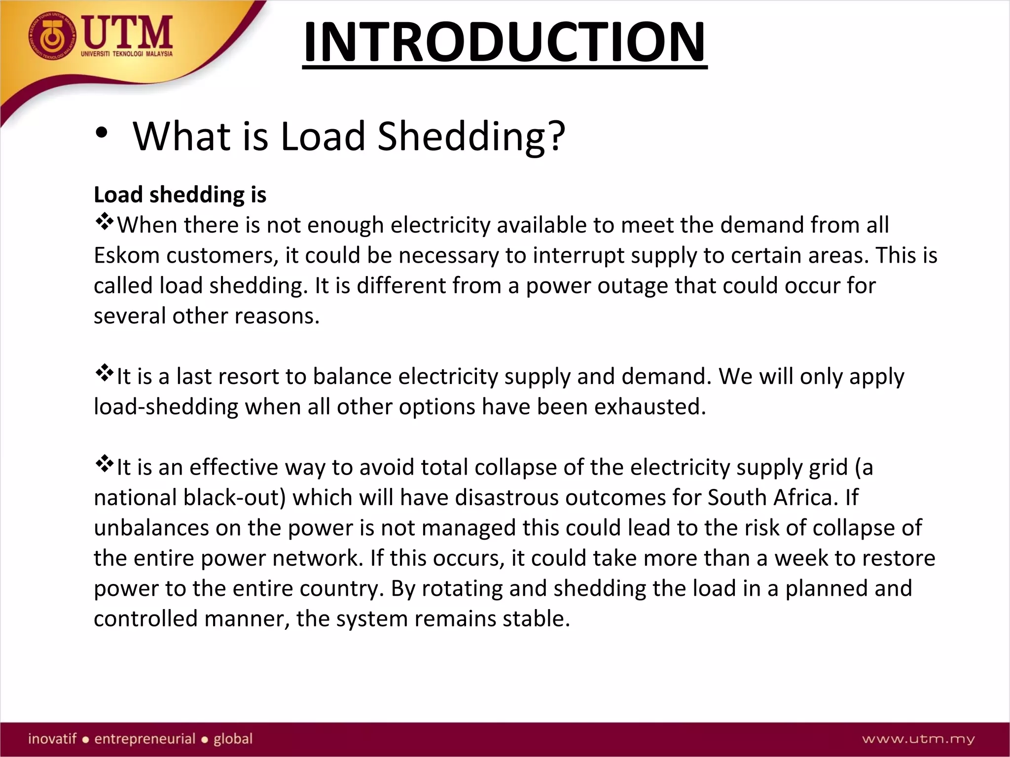
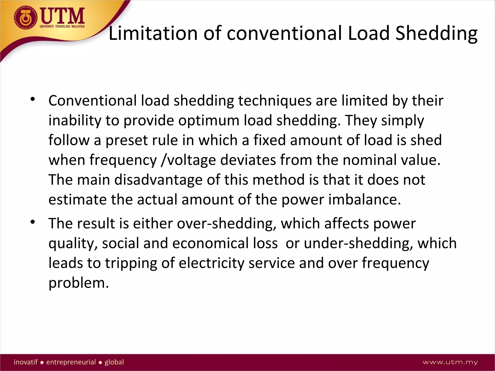
![Problem Statement
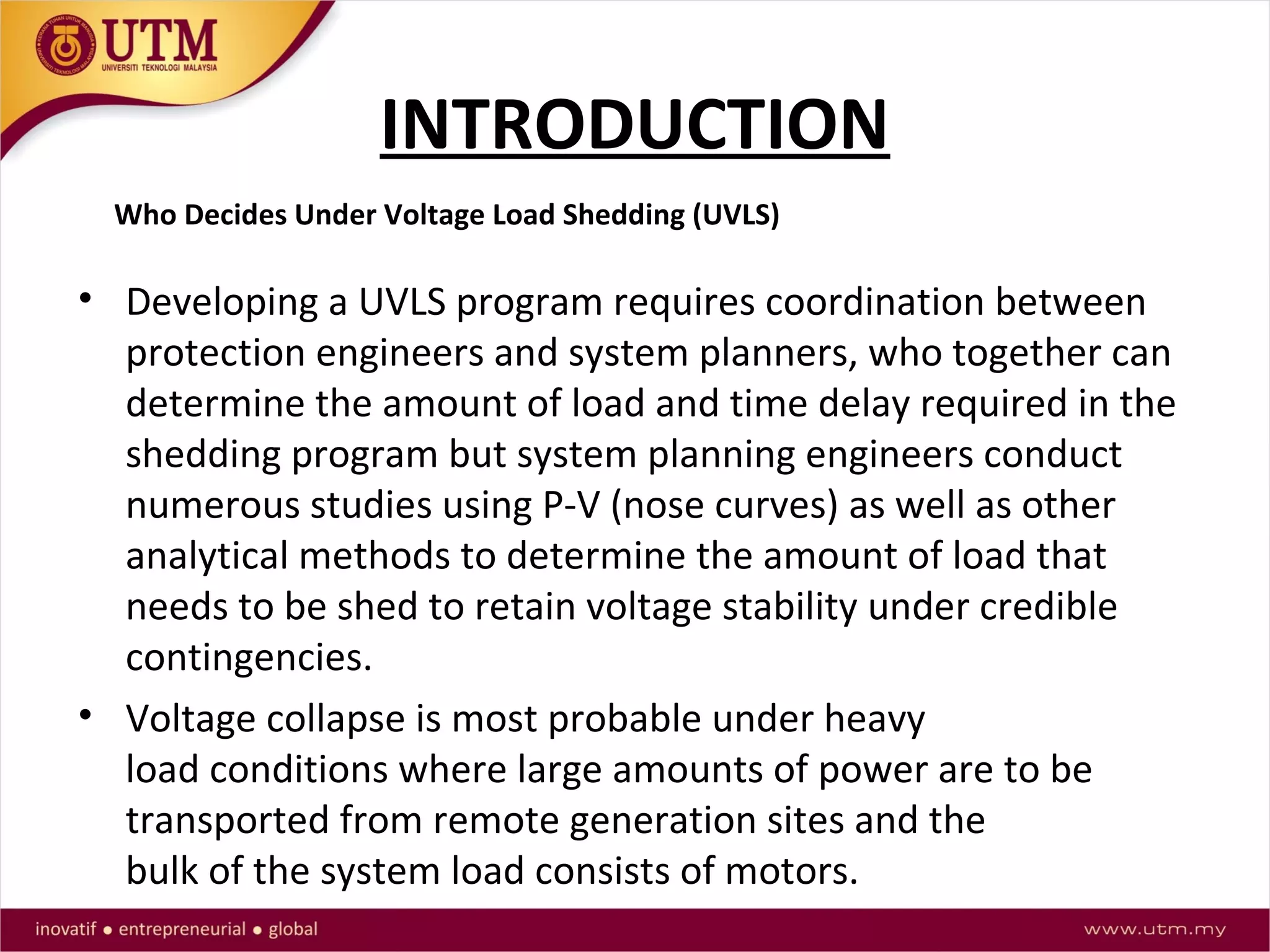
UVLS techniques are implemented to protect the power
system from voltage collapse. A look at major power
blackouts that have occurred around the world show that
most were caused by voltage instability problems [4].
Voltage instability generally occurs due to either forced
outage of the generator or the line, or overloading. When this
happens, the reactive power demand in transmission lines
varies severely and may cause a blackout if not recovered
quickly.](https://image.slidesharecdn.com/undervoltageloadshedding-150615035142-lva1-app6892/75/Under-voltage-load-shedding-10-2048.jpg)
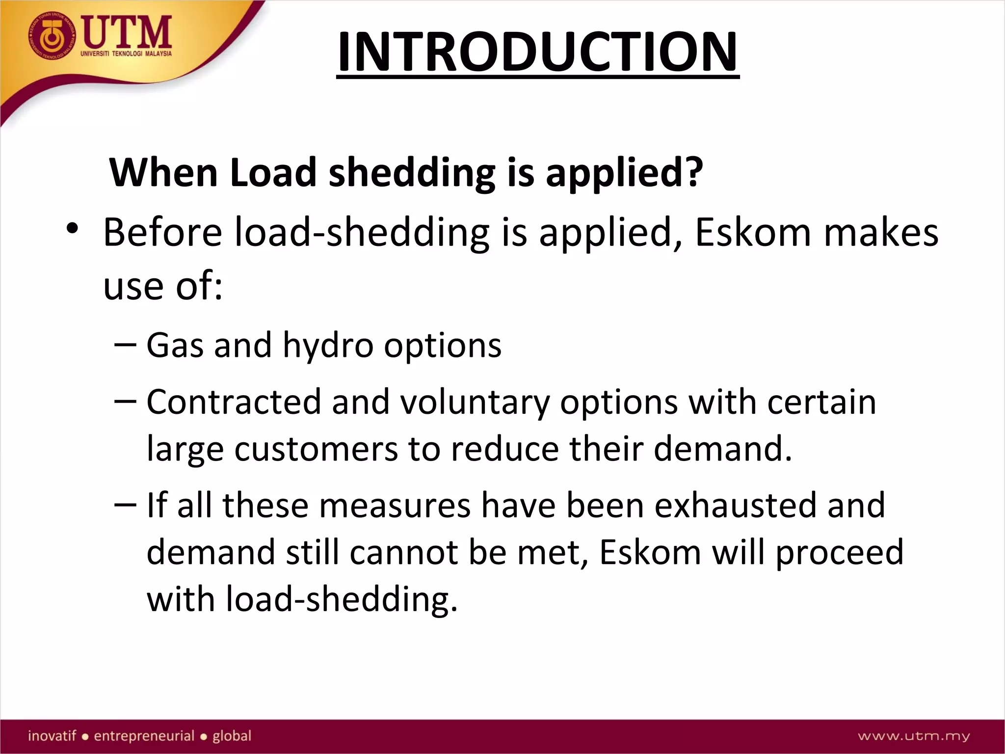
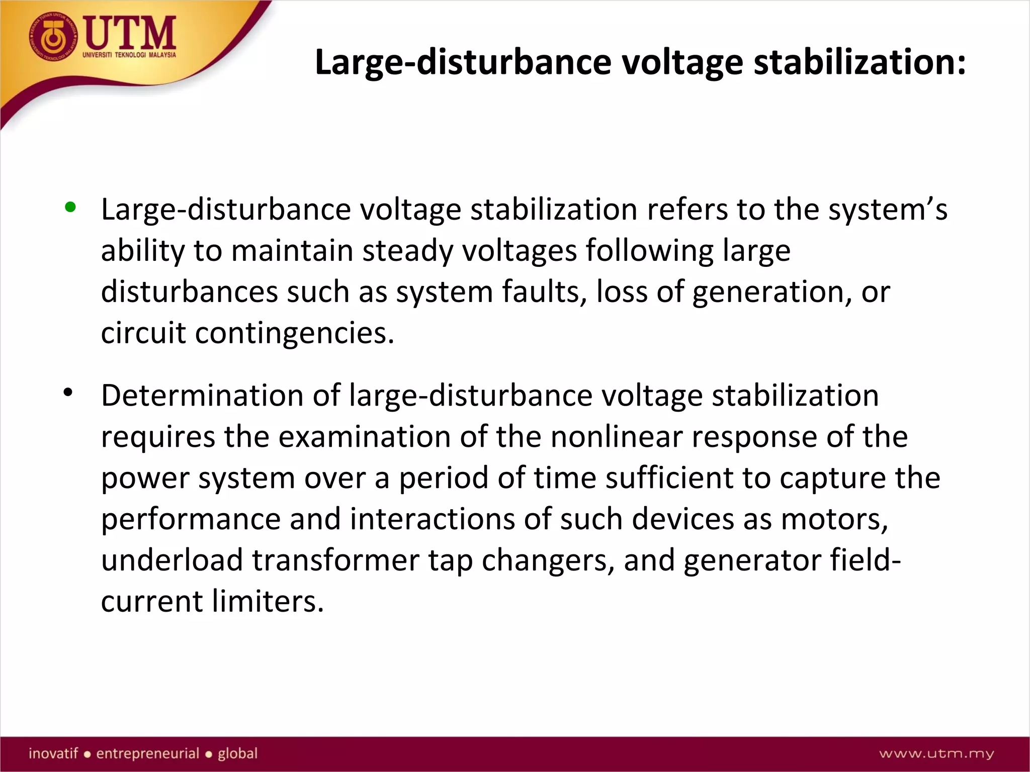
![Voltage Stabilization in Power Systems
Voltage stabilization refers to the ability of a power
system to maintain steady voltages at all buses in the
system after being subjected to a disturbance from a
given initial operating condition. It depends on the
ability to maintain/restore equilibrium between load
demand and load supply from the power system. [1]](https://image.slidesharecdn.com/undervoltageloadshedding-150615035142-lva1-app6892/75/Under-voltage-load-shedding-12-2048.jpg)
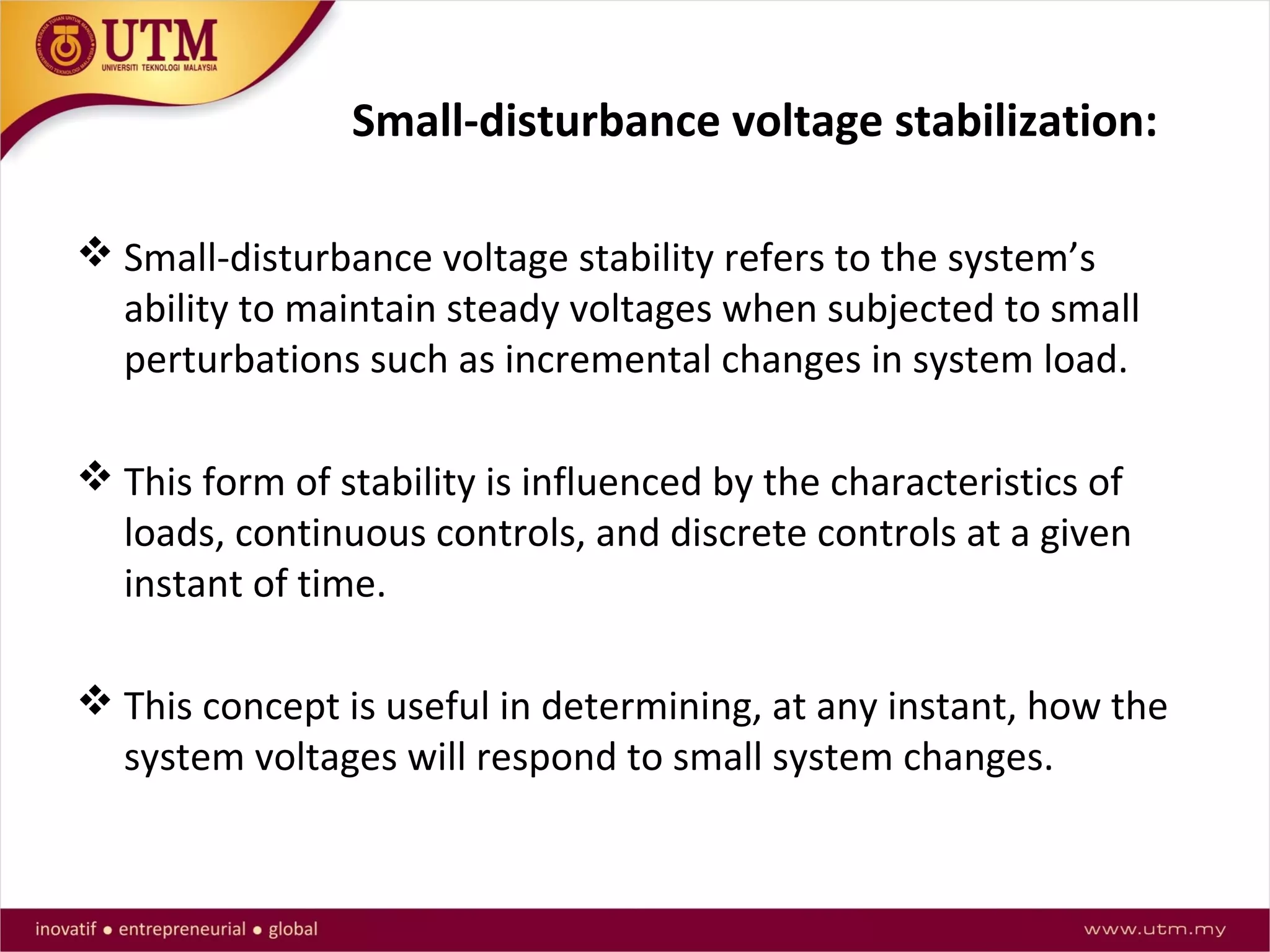
![Voltage Stabilization in Power Systems
Why we need voltage stabilization?
Instability that may result occurs in the form of a progressive
fall or rise of voltages of some buses.
A possible outcome of voltage instability is loss of load in an
area, or tripping of transmission lines and other elements by
their protective systems leading to cascading outages. Loss of
synchronism of some generators may result from these
outages or from operating conditions that violate field
current limit. [1]](https://image.slidesharecdn.com/undervoltageloadshedding-150615035142-lva1-app6892/75/Under-voltage-load-shedding-16-2048.jpg)
![Voltage Stabilization in Power Systems
The type of Dynamic / Nonlinear load can also cause the
voltage instability.
While the most common form of voltage instability is the
power frequency variation, the progressive drop of bus
voltages, and the overvoltage instability.
Overvoltage can be caused by a capacitive behavior of the
network as well as by under excitation limiters preventing
generators and synchronous compensators from absorbing
the excess reactive power. [1]](https://image.slidesharecdn.com/undervoltageloadshedding-150615035142-lva1-app6892/75/Under-voltage-load-shedding-18-2048.jpg)
![The time frame of interest for voltage
stabilization problems may vary from a few
seconds to tens of minutes.
Therefore, voltage stabilization may be either
a short-term or a long-term phenomenon. [2]
Short-term voltage stabilization involves
dynamics of fast acting load components such
as induction motors, electronically controlled
loads. (several seconds)
Long-term voltage stabilization involves
slower acting equipment such as tap-changing
transformers, generator current limiters.
(several mins)](https://image.slidesharecdn.com/undervoltageloadshedding-150615035142-lva1-app6892/75/Under-voltage-load-shedding-20-2048.jpg)
![Voltage Stabilization Techniques in Power Systems
.
Most sensitive loads which cause voltage instability
i. Induction Motors
ii. Discharge type Lamps
iii. Thermostatic Controlled Loads
iv. Load behind Under Load Tap Changers (ULTC)
The driving force for voltage instability is usually the loads. In
response to a disturbance, power consumed by the loads
should be restored.
A situation causing voltage instability occurs when load
dynamics attempt to restore power consumption beyond the
capability of the transmission network and the connected
generation.[1]
What cause voltage instability?](https://image.slidesharecdn.com/undervoltageloadshedding-150615035142-lva1-app6892/75/Under-voltage-load-shedding-36-2048.jpg)
![References
[1] C. P. Steinmetz, “Power control and stability of electric generating stations,” AIEE
Trans., vol. XXXIX, Part II, pp. 1215–1287, July 1920.
[2] AIEE Subcommittee on Interconnections and Stability Factors, “First report of power
system stability,” AIEE Trans., pp. 51–80, 1926.
[3] P. Kundur, J. Paserba, V. Ajjarapu, G. Andersson, A. Bose, C. Canizares, N.
Hatziargyriou, D. Hill, A. Stankovic, C. Taylor, T. Van Cutsem, and V. Vittal, "Definition
and Classification of Power System Stability IEEE/CIGRE Joint Task Force on Stability
Terms and Definitions," IEEE Transactions on Power Systems, vol. 19, pp. 1387- 1401,
2004
[4] El-Sadek MZ. Preventive measures for voltage collapses and voltage failures in the
Egyptian power system. Electr Power Syst Res 1998;44:203–11 .
[5] Amraee T, Mozafari B, Ranjbar AM. An improved model for optimal under voltage
load shedding: particle swarm approach. IEEE Power India Conf 2006:6.
[6] J.A. Laghari, H. Mokhlis, A.H.A. Bakar, H. Mohamad., “Application of computational
intelligence techniques for load shedding in power systems: A review”, Energy
Conversion and Management, 2013, 75, pp. 130-140.
[7] C. J. Mozina, Power Plant Protection and Control Strategies for Blackout Avoidance,
Georgia Tech Protective Relay Conference, April 2005.](https://image.slidesharecdn.com/undervoltageloadshedding-150615035142-lva1-app6892/75/Under-voltage-load-shedding-48-2048.jpg)
![References
[8] North American Electric Reliability Council (NERC), 1987 System Disturbance Report, p19, July
1998.
[9] IEEE Power System Relaying Committee Report, Summary of System Protection and Voltage
Stability, Transactions on Power Delivery, Vol. 10. No. 2, April 1995.
[10] R. Verayiah, A. Mohamed, H.Shareef, I. Z. Abidin, “Review of Under-voltage Load Shedding
Schemes in Power System Operation” PRZEGLĄD ELEKTROTECHNICZNY, 2014, 90, pp.99 -103
[11] Sadati N, Amraee T, Ranjbar AM, “A global particle swarmbased-simulated annealing
optimization technique for undervoltage load shedding problem”. Appl Soft Comput 2009;9:652–
7.
[12 ] J. Kennedy, R. Eberhart, “Particle Swarm Optimization”, IEEE International Conference on
Neural Networks, Piscataway, NJ, pp. 1942-1948, 1995
[13] Amraee T, Ranjbar AM, Mozafari B, Sadati N. An enhance under voltage load shedding
scheme to provide voltage stability. Electr Power Syst Res 2007;77(8):1038–46.
[14] Amraee T, Ranjbar AM, Feuillet R. Adaptive under-voltage load shedding scheme using
model predictive control. Int J Electr Power Syst Res 2011;81(7):1507–13.](https://image.slidesharecdn.com/undervoltageloadshedding-150615035142-lva1-app6892/75/Under-voltage-load-shedding-49-2048.jpg)
![References
[15] S. A. Pourmousavi and M. H. Nehrir, “Real-time central demand response for primary
frequency regulation in microgrids,” IEEE Trans. Smart Grid, vol. 3, no. 4, pp. 1988–1996, Dec.
2012.
[16] F. Katiraei, M. R. Iravani, and P. W. Lehn, “Micro-grid autonomous operation during and
subsequent to islanding process,” IEEE Trans. Power Del., vol. 20, no. 1, pp. 248–257, Jan. 2005.
[17] IEEE Recommended Practice for Industrial and Commercial Power System Analysis, IEEE
Standard 399-1997, Aug. 1998.
[18] F. Echavarren, E. Lobato, R. Rouco, M. Navarrete, R. Casanova, and G. López, "A load
shedding algorithm for improvement of load margin to voltage collapse," in Power Tech
Conference Proceedings, 2003 IEEE Bologna, 2003, p. 6 pp. Vol. 1.
[19] B. Otomega and T. Van Cutsem, "Undervoltage load shedding using distributed controllers,"
Power Systems, IEEE Transactions on, vol. 22, pp. 1898-1907, 2007.
[20] A. Ketabi and M. H. Fini, “An underfrequency load shedding scheme for islanded microgrids,”
Int. J. Elect. Power Energy Syst., vol. 62, pp. 599–607, Nov. 2014.
[21] U. Rudez and R. Mihalic, “Monitoring the first frequency derivative to improve adaptive
underfrequency load-shedding schemes,” IEEE Trans. Power Syst., vol. 26, no. 2, pp. 839–846,
May 2011.](https://image.slidesharecdn.com/undervoltageloadshedding-150615035142-lva1-app6892/75/Under-voltage-load-shedding-50-2048.jpg)
![References
[22] A. Saffarian and M. Sanaye-Pasand, “Enhancement of power system stability
using adaptive combinational load shedding methods,” IEEE Trans. Power Syst., vol.
26, no. 3, pp. 1010–1020, Aug. 2011.
[23] Hosseini-Bioki MM, Rashidinejad M, Abdollahi A. An implementation of particle
swarm optimization to evaluate optimal under voltage load shedding in competitive
electricity markets. J Power Sour 2013;242:122–31.
[24] Ahmad Ahmadi ,Yousuf Alinejad-Beromi A new integer-vale modeling of
optimal load shedding to prevent voltage stability. Electrical Power and Energy
Systems 65(2015)210-219.](https://image.slidesharecdn.com/undervoltageloadshedding-150615035142-lva1-app6892/75/Under-voltage-load-shedding-51-2048.jpg)


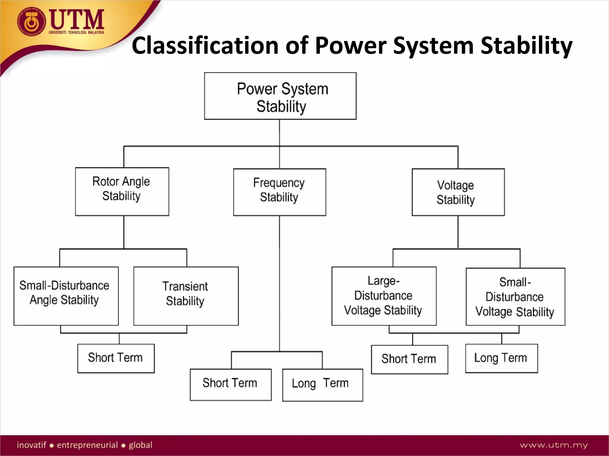
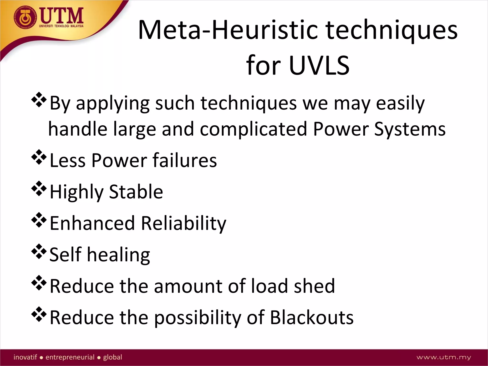
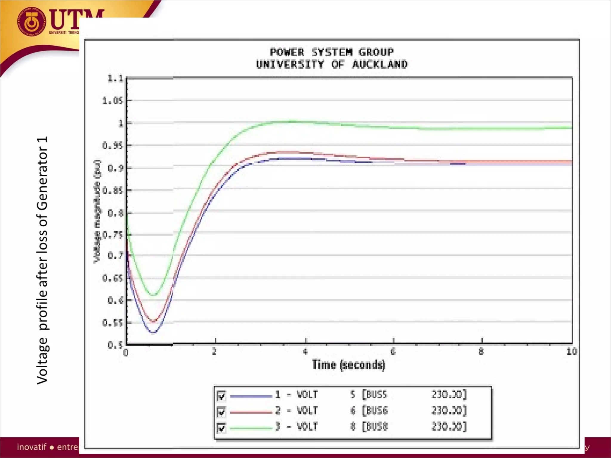
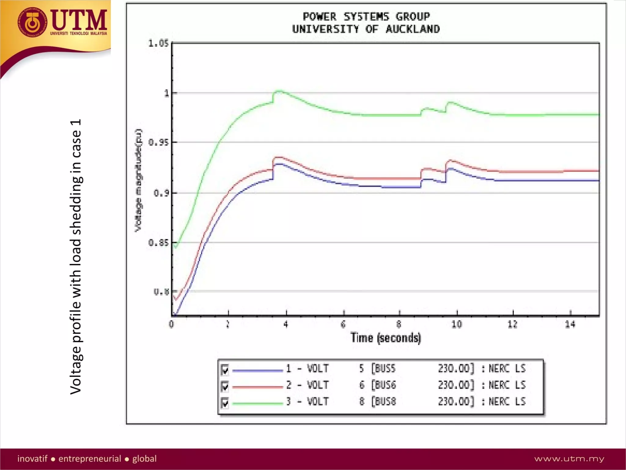
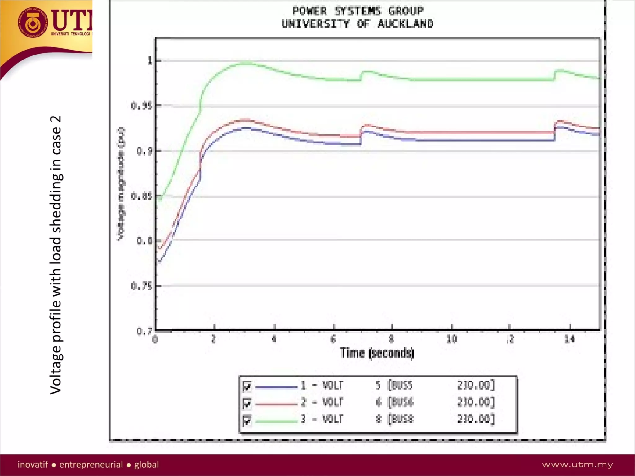
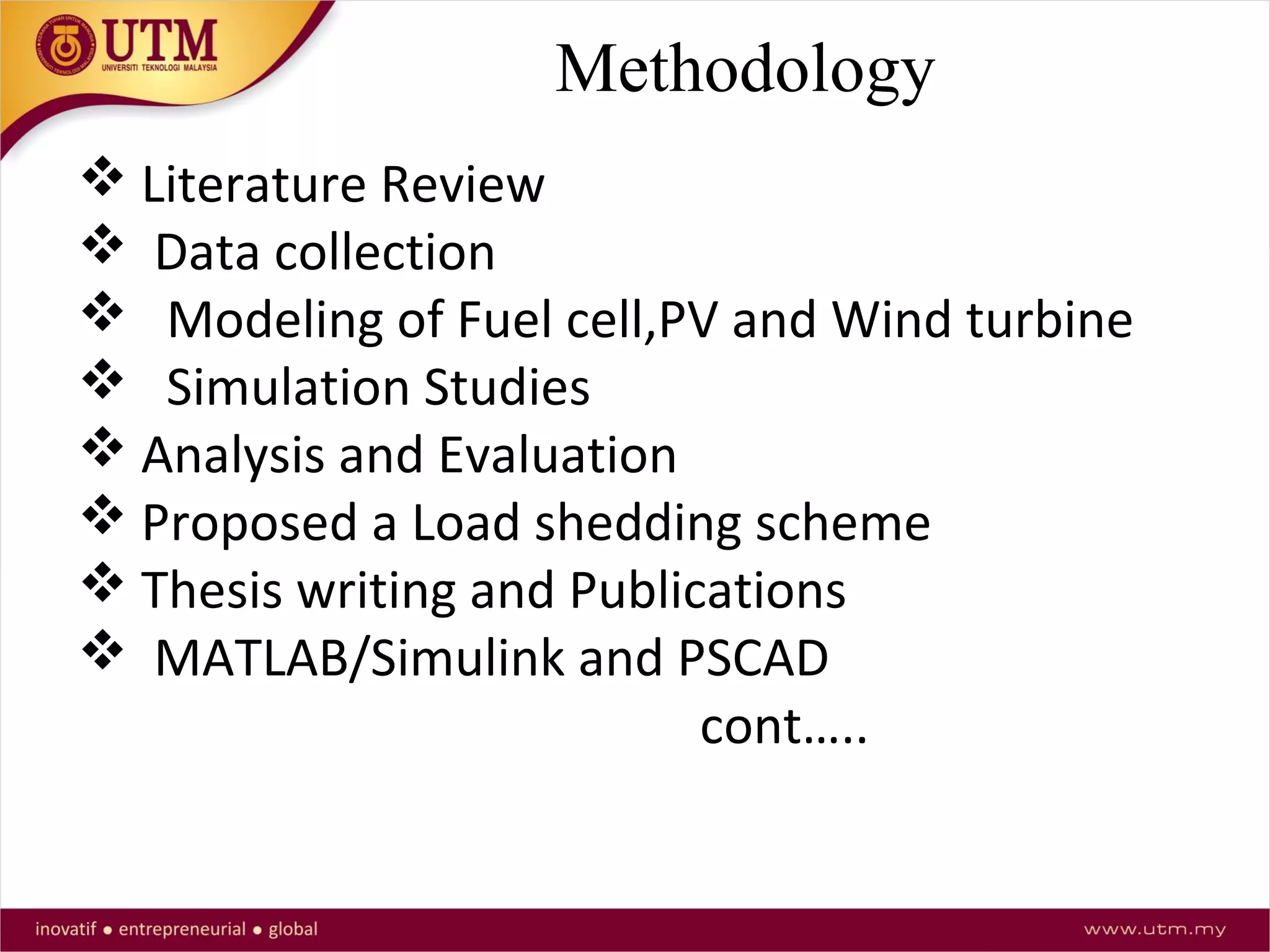
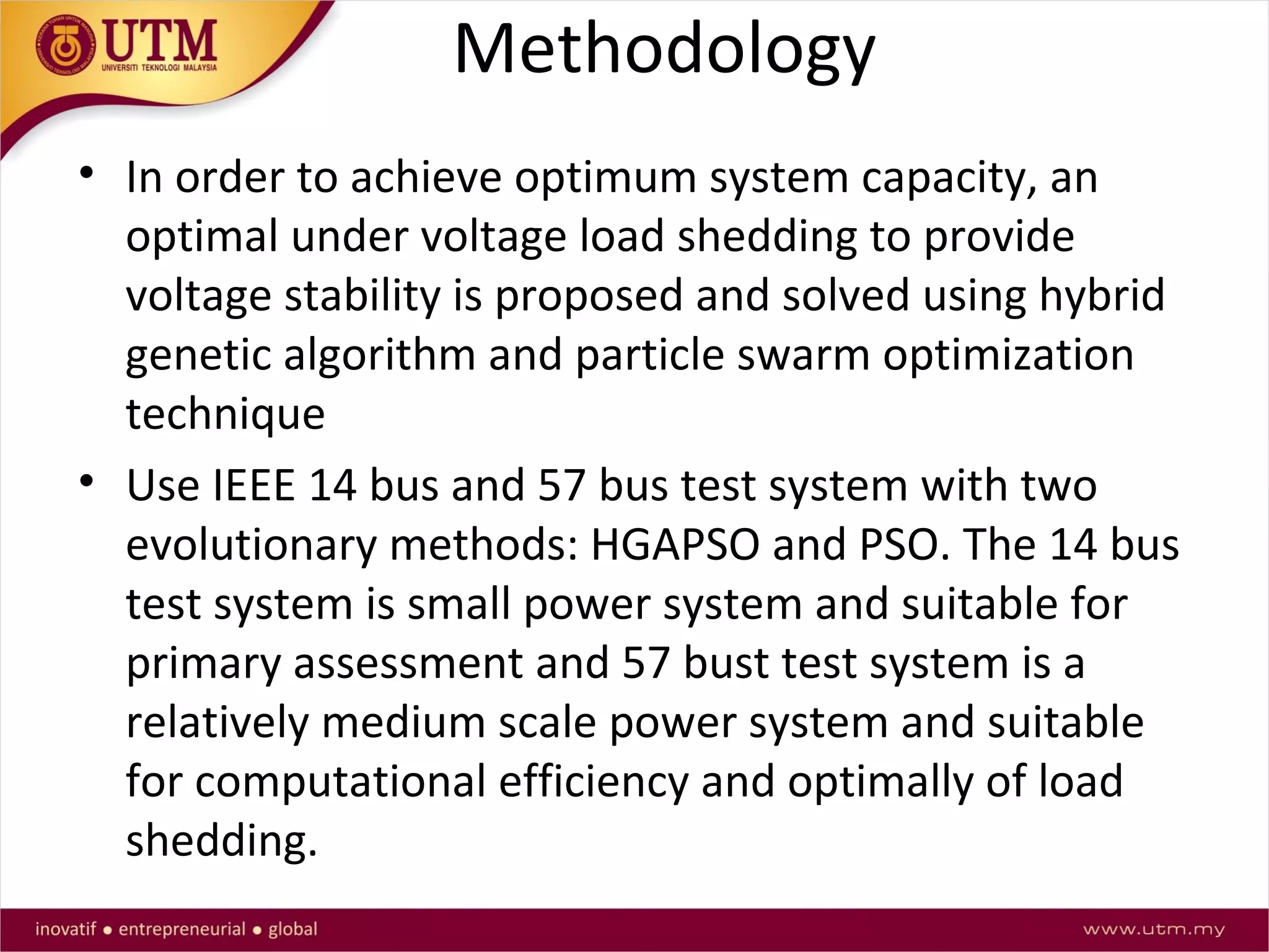
This document presents a thesis proposal on developing an optimal under voltage load shedding scheme using hybrid meta-heuristic techniques. The introduction provides background on load shedding, noting it is implemented as a last resort to balance supply and demand and avoid blackouts. The objectives are to propose a novel hybrid optimization technique considering voltage stability and develop a load shedding scheme to minimize shed load and prevent overloading. Key aspects of voltage stability and classifications of power system stability are reviewed. The methodology will apply hybrid meta-heuristic techniques like genetic algorithms and particle swarm optimization to handle large, complex power systems and provide better load shedding results than conventional techniques.