Downloaded 898 times

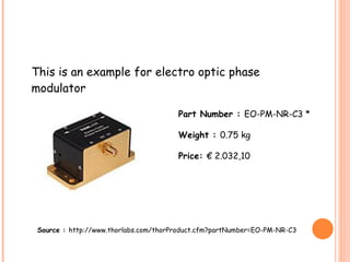


This document summarizes an electro-optic modulator final project. It describes three types of optic modulators including electro-optic modulators, which use an external voltage to modify a nonlinear crystal's refractive index. Pockels cells are described as using this electro-optic effect to modulate laser beams for applications like optical communication. The document outlines different electro-optic modulator types including phase and intensity modulators built using Pockels cells and interferometers. It provides details on design considerations, materials like lithium niobate, and evaluates a research paper on building a polarization-insensitive waveguide modulator.


![[Graham t. reed]_silicon_photonics__an_introductio(z-lib.org)](https://cdn.slidesharecdn.com/ss_thumbnails/grahamt-200704124405-thumbnail.jpg?width=640&height=640&fit=bounds)


