Downloaded 13 times
![IJSRD - International Journal for Scientific Research & Development| Vol. 3, Issue 10, 2015 | ISSN (online): 2321-0613
All rights reserved by www.ijsrd.com 855
A Study on Uniform and Apodized Fiber Bragg Gratings
Gayathri Prasad. S1
Reshmi Krishnan. G2
1,2
Department of Optoelectronics
1,2
University of Kerala
Abstract— The design, simulation and analysis of an optical
Fiber Bragg Grating for maximum reflectivity, minimum
side lobe power wastage has been done using MATLAB
software. The reflection spectra and side lobes strength were
analyzed with different grating lengths, refractive index
profiles and pitch values. The simulations are based on
coupled mode equations and transfer matrix method that
describes the interaction of guided modes.
Key words: Uniform and Apodized Fiber, Bragg Gratings,
Grating Lengths
I. INTRODUCTION
Fiber Bragg Gratings (FBGs) have emerged as an important
element, mostly in fiber optic communications and optical
sensing fields. A fiber Bragg grating consists of a periodic
modulation of the refractive index within the core of a single
mode optical fiber, where the phase fronts are perpendicular
to the longitudinal axis of the fiber and with grating planes
having a constant period. Light gets scattered at each grating
plane while being guided through the fiber core. The
partially reflected light from each grating plane gets added
up upon satisfying the Bragg condition. Thus the energy
gets transferred from the forward propagating to the
backward propagating mode [1]. The FBG therefore reflects
certain wavelengths keeping propagation of other
wavelengths practically unaffected. The refractive index
profile may be uniform, apodized or chirped depending
upon the induced change of core refractive index.
Apodization refers to the minimization of power wasted in
side lobes by the application of different index profiles.
Chirped gratings have a linear variation in the grating
period, which broadens the reflected spectrum.
II. METHODS FOR SIMULATION OF FBG
The most commonly chosen and accurate mathematical
model for design of FBGs is the Coupled Mode Theory
(CMT). In this paper, the equations of CMT are used to
describe the spectral properties of FBG. Another fast and
accurate technique is the Transfer Matrix Method (TMM),
in which the whole grating is divided into sub-sections and
the input and output fields of each sub-section is calculated
and multiplied to get the total grating response. Parameters
of FBG, such as period of refractive index perturbation,
magnitude of refractive index, grating length and numbers
of grids, give optical properties of FBG [2].
A. Equations Of Coupled Mode Theory
When light passes through the FBG, the narrowband
spectral component at the Bragg wavelength is reflected by
the FBG. The Bragg wavelength is given by the below
equation:
λB=2neffΛ (2.1)
where neff and Λ are the effective refractive index of the
fiber and the pitch of the grating respectively. The refractive
index variations with a period Λ along the length of the fiber
are generally expressed as:
n(z)=n0+Δn(z) cos(2π/Λ+θ(z)) (2.2)
The functions Δn(z) and θ(z) are slowly varying functions
compared to the grating period Λ, n0 is the core refractive
index, and Δn(z) the envelope of the refractive index
modulation. The parameter θ(z) defines locally, the phase of
the effective index modulation, which is used to describe
phase shifts or gating chirp. Considering only unchirped
gratings, θ(z)=0 [4].
Coupling coefficient, q(z)=π Δn(z) / 2n0 Λ (2.3)
Detuning, δ = 2 πn0 /λ – π/Λ (2.4)
Reflection Coefficient is given by:
ρ(δ)= -qsinh(γL)/( δ sinh(γL)+iγcosh(γL)) (2.5)
Reflectivity,
R(δ)= sinh2
(γL)/ [cosh2
(γL)- δ2
/q2
] (2.6)
Maximum reflectivity Rmax occurs when the resonance
condition is observed; i.e., δ=0 and is given by:
Rmax=tanh2
(qL) (2.7)
B. Apodization
The power wasted in side lobes can be minimized by
applying different index profiles, called as Apodization.
Doping concentration variation limits the index variation to
maximum value ∆n0. Index inside core after FBG has been
printed can be expressed by the below equation.
n(z) = nco + ∆n0. A(z).nd(z) (2.8)
where nco is the core refractive index, nd(z) is the index
variation function, ∆n0 is the maximum index variation and
A(z) is the anodization function. For uniform FBG with no
anodization index variation function A=1.
III. SIMULATION RESULTS
The simulation works presented in this paper are done using
Matlab R2010a software.
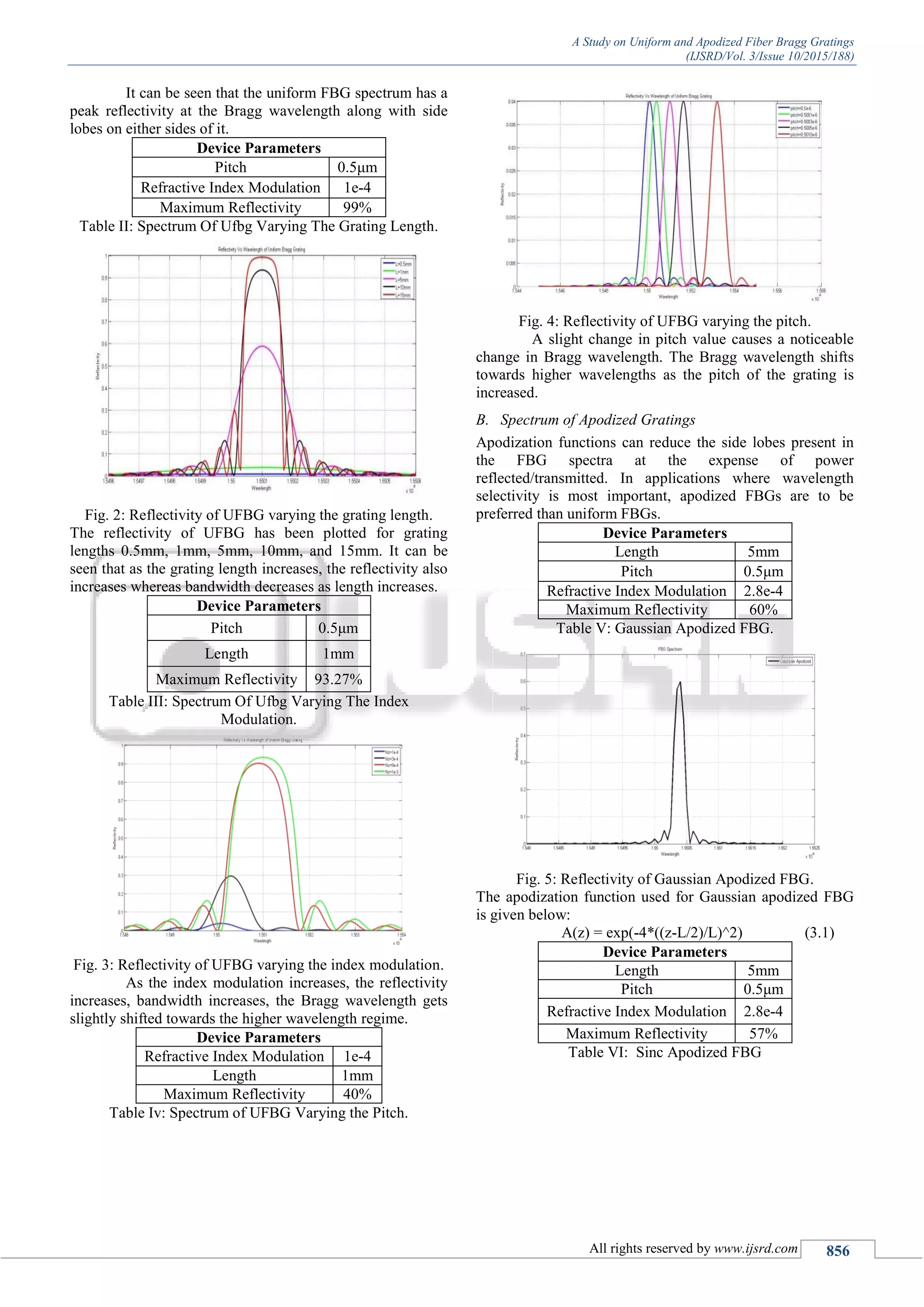
A. Spectrum Of Uniform Fiber Bragg Grating
Device Parameters
Length 3mm
Pitch 0.499μm
Refractive Index Modulation 5.15e-4
Maximum Reflectivity 100%
Table 1: Uniform FBG.
Fig. 1: Reflectivity/Transmittivity of UFBG.](https://image.slidesharecdn.com/ijsrdv3i100639-160128094545/75/A-Study-on-Uniform-and-Apodized-Fiber-Bragg-Gratings-1-2048.jpg)
![A Study on Uniform and Apodized Fiber Bragg Gratings
(IJSRD/Vol. 3/Issue 10/2015/188)
All rights reserved by www.ijsrd.com 857
Fig. 6: Reflectivity of Sinc Apodized FBG.
The apodization function used for Sinc apodized FBG is
given below:
A(z)= 2*sinc(2*pi/L*(z-L/2)) (3.2)
Device Parameters
Length 5mm
Pitch 0.5μm
Refractive Index Modulation 2.8e-4
Maximum Reflectivity 11.8%
Table VII: Raised Cosine Apodized FBG.
Fig. 7: Reflectivity of Raised Cosine Apodized FBG.
The apodization function used for Raised Cosine apodized
FBG is given below:
A(z) =1.05*(1+cos((pi*z-0.5*L)/L)) (3.3)
IV. CONCLUSION
The spectral properties of FBG are affected by changes in
grating length, refractive index modulation and pitch of the
grating. The reflectivity increases with increase in length
whereas bandwidth decreases as length increases.
Apodization functions can reduce the side lobes present in
the FBG spectra at the expense of power
reflected/transmitted. The reflectivity is very less for raised
cosine apodized gratings, but very good suppression of side
lobes is achieved. In applications where wavelength
selectivity is most important, apodized FBGs are to be
preferred than uniform FBGs.
REFERENCES
[1] Turan Erdogan, Fiber Grating Spectra, Journal Of
Lightwave Technology, Vol. 15, No. 8, August 1997
[2] Sunita Ugale, Dr. V. Mishra, Fiber Bragg Grating
Modeling, Characterization And Optimization With
Different Index Profiles, International Journal Of
Engineering Science And Technology Vol. 2(9), 2010
[3] Abdallah Ikhlef, Rachida Hedara, Mohamed Chikh-
Bled, Uniform Fiber Bragg Grating Modeling And
Simulation Used Matrix Transfer Method, Ijcsi
International Journal Of Computer Science Issues, Vol.
9, Issue 1, No 2, January 2012
[4] Andreas Othonos, Kyriacos Kalli, Fiber Bragg
Gratings-Fundamentals And Applications In
Telecommunications And Sensing.
[5] Raman Kashyap, Fiber Bragg Gratings](https://image.slidesharecdn.com/ijsrdv3i100639-160128094545/75/A-Study-on-Uniform-and-Apodized-Fiber-Bragg-Gratings-3-2048.jpg)

This document summarizes a study on modeling uniform and apodized fiber Bragg gratings (FBGs) using MATLAB. The authors simulate different FBG designs and analyze their reflection spectra and side lobe strengths. Uniform FBGs are affected by changes in grating length, refractive index modulation, and pitch. Increasing length increases reflectivity but decreases bandwidth, while increasing index modulation increases reflectivity and bandwidth. Apodized FBGs using Gaussian, sinc, and raised cosine profiles reduce side lobes compared to uniform FBGs, at the cost of lower reflectivity. Apodized FBGs are preferred over uniform FBGs when wavelength selectivity is important.