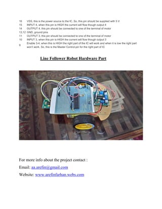
1. LINE FOLLOWER ROBOT
Ahmed Amirul Arefin
Department of Electrical & Electronics Engineering
United International University
2. Line Follower Robot
A line follower robot is basically a robot designed to follow a ‘line’ or path already
predetermined by the user. This line or path may be as simple as a physical white line on the
floor or as complex path marking schemes e.g. embedded lines, magnetic markers and laser
guide markers. In order to detect these specific markers or ‘lines’, various sensing schemes can
be employed. These schemes may vary from simple low cost line sensing circuit to expansive
vision systems. The choice of these schemes would be dependent upon the sensing accuracy and
flexibility required. From the industrial point of view, line following robot has been implemented
in semi to fully autonomous plants. In this environment, these robots functions as materials
carrier to deliver products from one manufacturing point to another where rail, conveyor and
gantry solutions are not possible. Apart from line following capabilities, these robots should also
have the capability to navigate junctions and decide on which junction to turn and which junction
ignore. This would require the robot to have 90 degree turn and also junction counting
capabilities. To add on to the complexity of the problem, sensor positioning also plays a role in
optimizing the robots performance for the tasks mentioned earlier.
Line-following robots with pick- and- placement capabilities are commonly used in
manufacturing plants. These move on a specified path to pick the components from specified
locations and place them on desired locations. Basically, a line-following robot is a self-
operating robot that detects and follows a line drawn on the floor. The path to be taken is
indicated by a white line on a black surface. The control system used must sense the line and
man oeuvre the robot to stay on course while constantly correcting the wrong moves using
feedback mechanism, thus forming a simple yet effective closed- loop system.
3. Using Components
• Hardware Part
• AT-89C51 Microcontroller
• Microcontroller PCB board
• IR Sensor
• Motor Driver (L239D)
• Robotics Kits
• Program Burner (TL866 Universal Program Burner )
• Software Part
• Using Assembly Language in McU 8051 IDE
• Proteus
Algorithm
4. Proteus Schematics
Assembly Code
You can make this code using assembly language and also the C-programming.
The most important thing how u arrange the logic so that’s why here is no code for
this project. If you face any problem to make this project code, you can email me
or you can message me in the website. The email address and website link is given
at last page of this paper .
IR Sensor
IR sensors use infrared light to sense objects in front of them and gauge their distance. The commonly
used Sharp IR sensors have two black circles which used for this process, an emitter and a detector (see
image right).
A pulse of infrared light is emitted from the emitter and spreads out in a large arc. If no object is detected,
then the IR light continues forever and no reading is recorded. However, if an object is nearby then the IR
light will be reflected and some of it will hit the detector. This forms a simple triangle between the object,
emitter and detector. The detector is able to detect the angle that the IR light arrived back at and thus can
determine the distance to the object. This is remarkably accurate and although interference from sunlight
is still a problem, these sensors are capable of detecting dark objects in sunlight now.
5. These sensors have three pins, generally with a red, black and yellow wire coming out of them. Red is
connected used to power the sensor, black is ground and yellow is the analogue output of the sensor. This
can be attached to one of the analogue in pins on the mbed (p15-p20) or suitable micro-controller and the
distance can be read as a voltage with low voltages corresponding to close objects and high voltages
corresponding to distant objects. For mbed use please see the Mbed Using Sensors documentation.
These sensors are far from perfect and have quite a small range. They are usually most effective (though
this depends on particular makes) at between 10cm to a maximum of about 1m. However, complex
scenery (many different objects) will cause a problem as the sensor will see all objects within the arc
created by the IR emitter. It is recommended that you search for the relevant data sheet or conduct simple
tests to find ideal values beyond which your robot acknowledged the obstacle. Sunlight or flames also
present a problem as they emit a lot of IR light and thus interfere with the IR sensor providing false
readings. However, these sensors are suitable for indoor use. Interference from other sensors can also be a
problem if there are multiple robots or parallel sensors. As with all analogue signals, noise will exist in
the readings taken from the sensor.
For simple obstacle avoidance it is sufficient to simply see the obstacles in front of you. However, for
more advanced avoidance or for searching it is advantageous to see all around your robot, or to at least
have a larger view angle. This could be achieved using two sensors, facing away from one another,
pointing left forwards and right forwards. This would allow a robot to identify which direction the
obstacle was in and thus turn away from it in the correct direction.
However, this approach is inefficient and can be limiting. Installing further IR sensors also throws up
problems of interference. Another solution is to use a servo to turn your IR sensor as you would swivel
your head or eyes. The servo can be set to many different angles and IR readings can be taken from each
of them. This can be extremely effective at building up a 3D map of the area around the robot.
Motor Driver IC(L239D)
A motor driver IC is an integrated circuit chip which is usually used to control motors in
autonomous robots. Motor driver ICs act as an interface between microprocessors in robots
and the motors in the robot. The most commonly used motor driver IC’s are from the L293
series such as L293D, L293NE, etc. These ICs are designed to control 2 DC motors
simultaneously. L293D consist of two H-bridge. H-bridge is the simplest circuit for
controlling a low current rated motor. For this tutorial we will be referring the motor driver IC
as L293D only. L293D has 16 pins, they are comprised as follows:
Ground Pins - 4
Input Pins - 4
Output Pins - 4
6. Enable pins - 2
Voltage Pins – 2
Why We Need Motor Driver IC?
Motor Driver ICs are primarily used in autonomous robotics only. Also most
microprocessors operate at low voltages and require a small amount of current to operate
while the motors require a relatively higher voltages and current . Thus current cannot be
supplied to the motors from the microprocessor. This is the primary need for the motor
driver IC.
How Motor Driver Operates?
The L293D IC receives signals from the microprocessor and transmits the relative signal to
the motors. It has two voltage pins, one of which is used to draw current for the working of
the L293D and the other is used to apply voltage to the motors. The L293D switches it
output signal according to the input received from the microprocessor.
For Example: If the microprocessor sends a 1(digital high) to the Input Pin of L293D, then
the L293D transmits a 1(digital high) to the motor from its Output Pin. An important thing to
note is that the L293D simply transmits the signal it receives. It does not change the signal
in any case.
L293D And Its Working
The L293D is a 16 pin IC, with eight pins, on each side, dedicated to the controlling of a
motor. There are 2 INPUT pins, 2 OUTPUT pins and 1 ENABLE pin for each motor. L293D
consist of two H-bridge. H-bridge is the simplest circuit for controlling a low current rated
motor.
The Theory for working of a H-bridge is given below.
Working Of A H-bridge
H-bridge is given this name because it can be modelled as four switches on the corners of
‘H’. The basic diagram of H-bridge is given below.
7. L239D Pin Diagram
In the diagram we can see that,
Pin
No.
Pin Characteristics
1
Enable 1-2, when this is HIGH the left part of the IC will work and when it is low the left part won’t
work. So, this is the Master Control pin for the left part of IC
2 INPUT 1, when this pin is HIGH the current will flow though output 1
3 OUTPUT 1, this pin should be connected to one of the terminal of motor
4,5 GND, ground pins
6 OUTPUT 2, this pin should be connected to one of the terminal of motor
7 INPUT 2, when this pin is HIGH the current will flow though output 2
8
VC, this is the voltage which will be supplied to the motor. So, if you are driving 12 V DC motors
then make sure that this pin is supplied with 12 V
8. 16 VSS, this is the power source to the IC. So, this pin should be supplied with 5 V
15 INPUT 4, when this pin is HIGH the current will flow though output 4
14 OUTPUT 4, this pin should be connected to one of the terminal of motor
13,12 GND, ground pins
11 OUTPUT 3, this pin should be connected to one of the terminal of motor
10 INPUT 3, when this pin is HIGH the current will flow though output 3
9
Enable 3-4, when this is HIGH the right part of the IC will work and when it is low the right part
won’t work. So, this is the Master Control pin for the right part of IC
Line Follower Robot Hardware Part
For more info about the project contact :
Email: aa.arefin@gmail.com
Website: www.arefinfarhan.webs.com