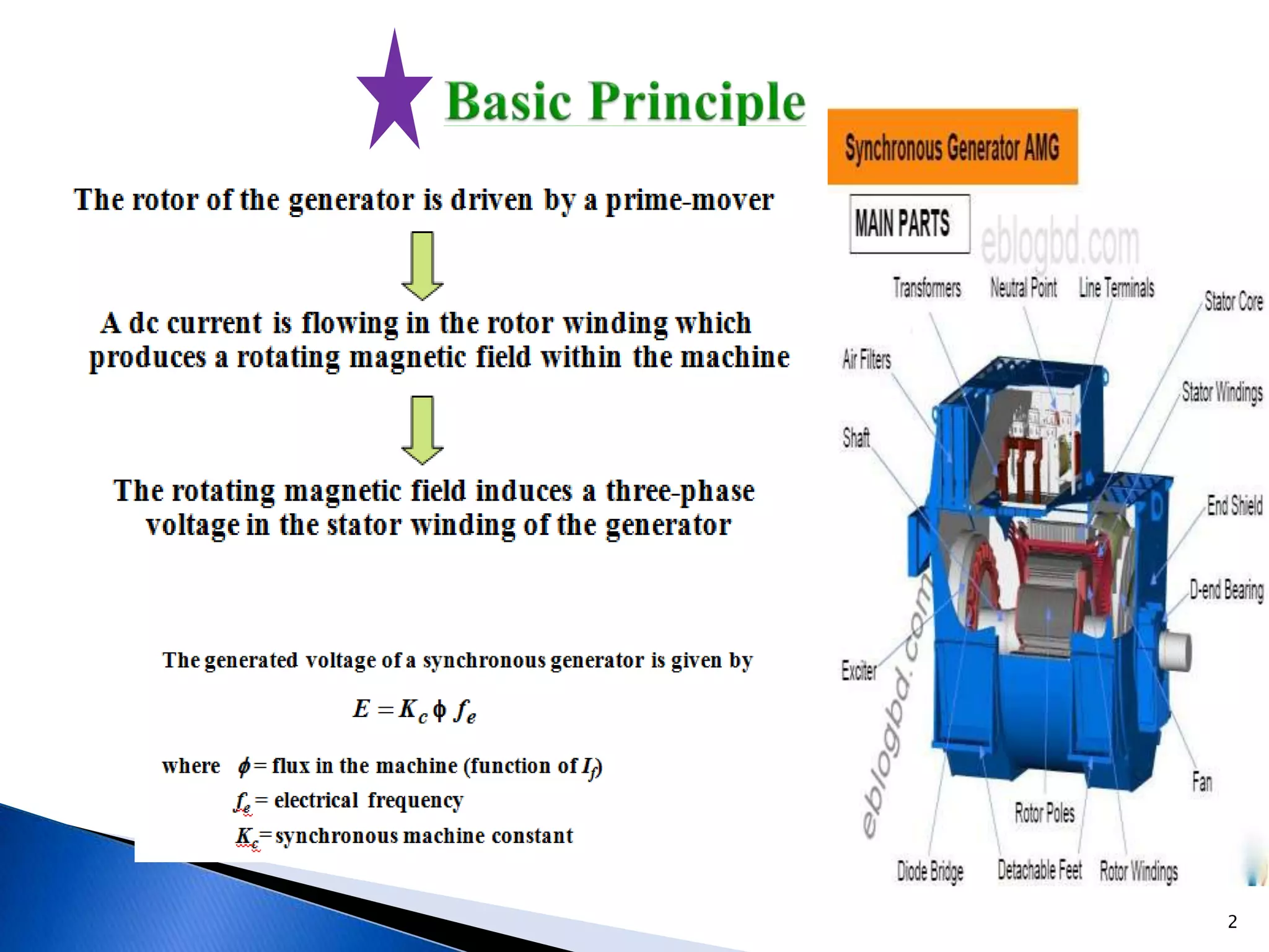
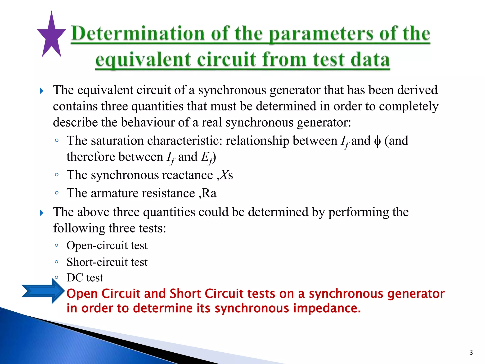
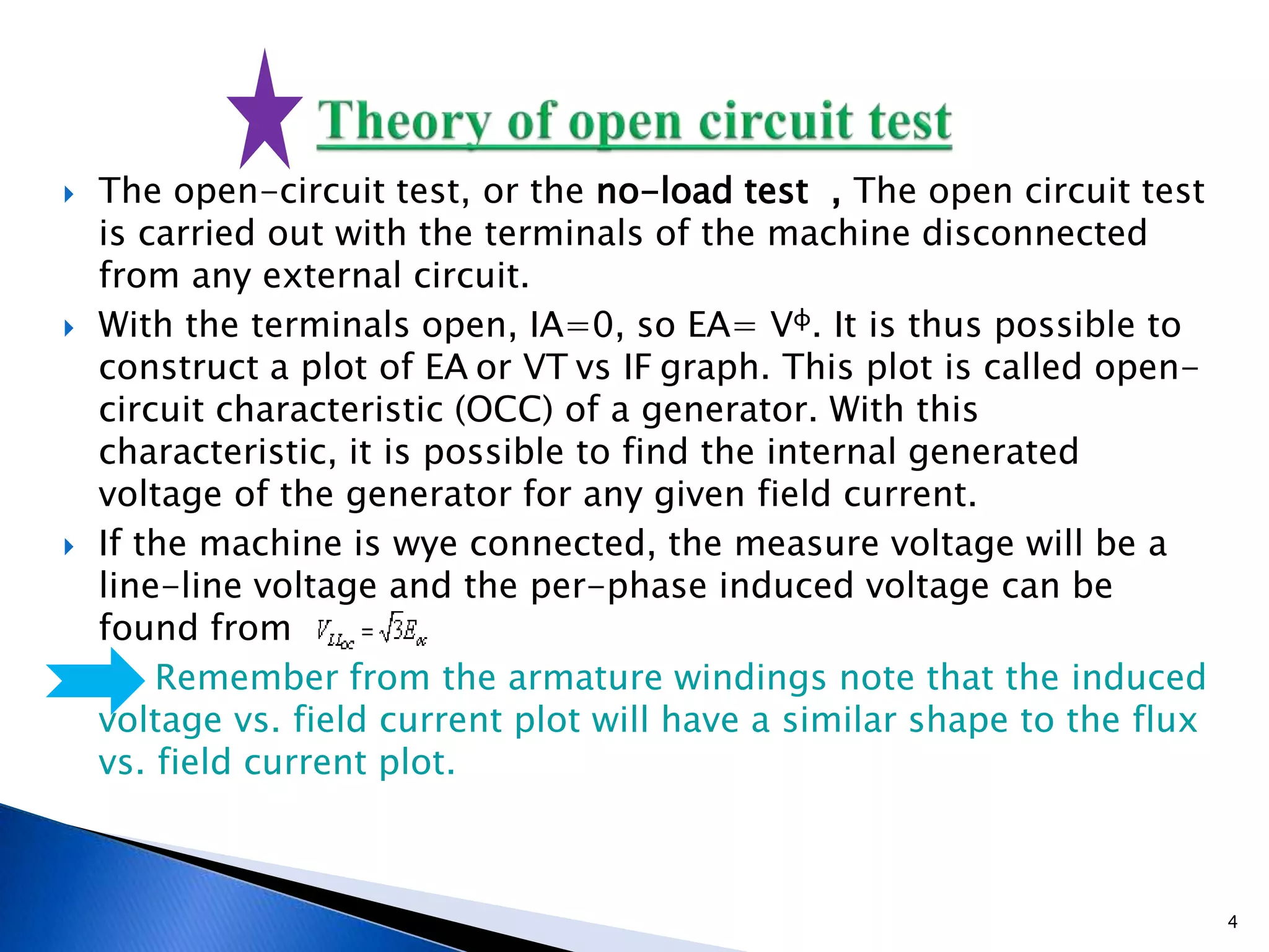
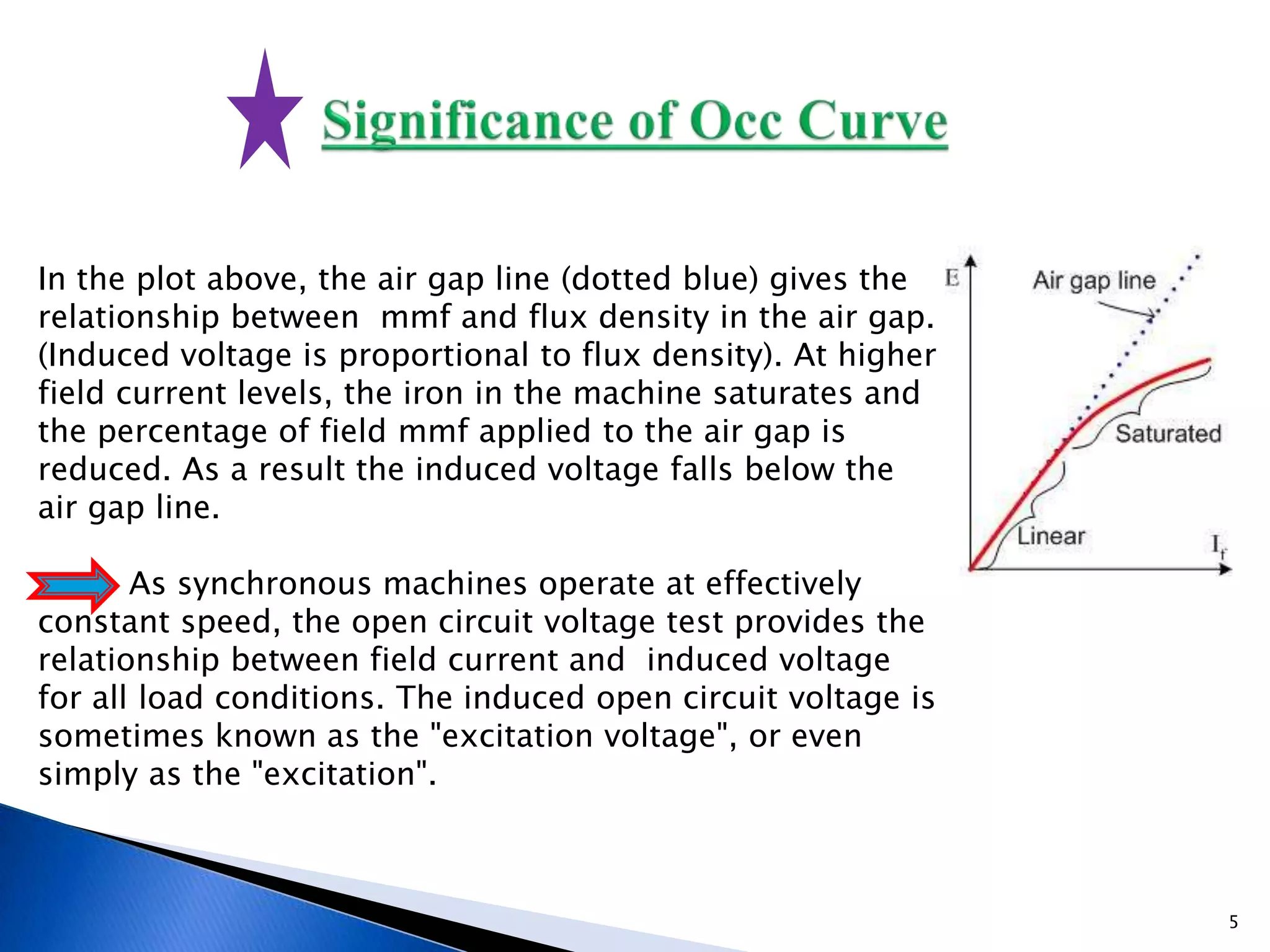
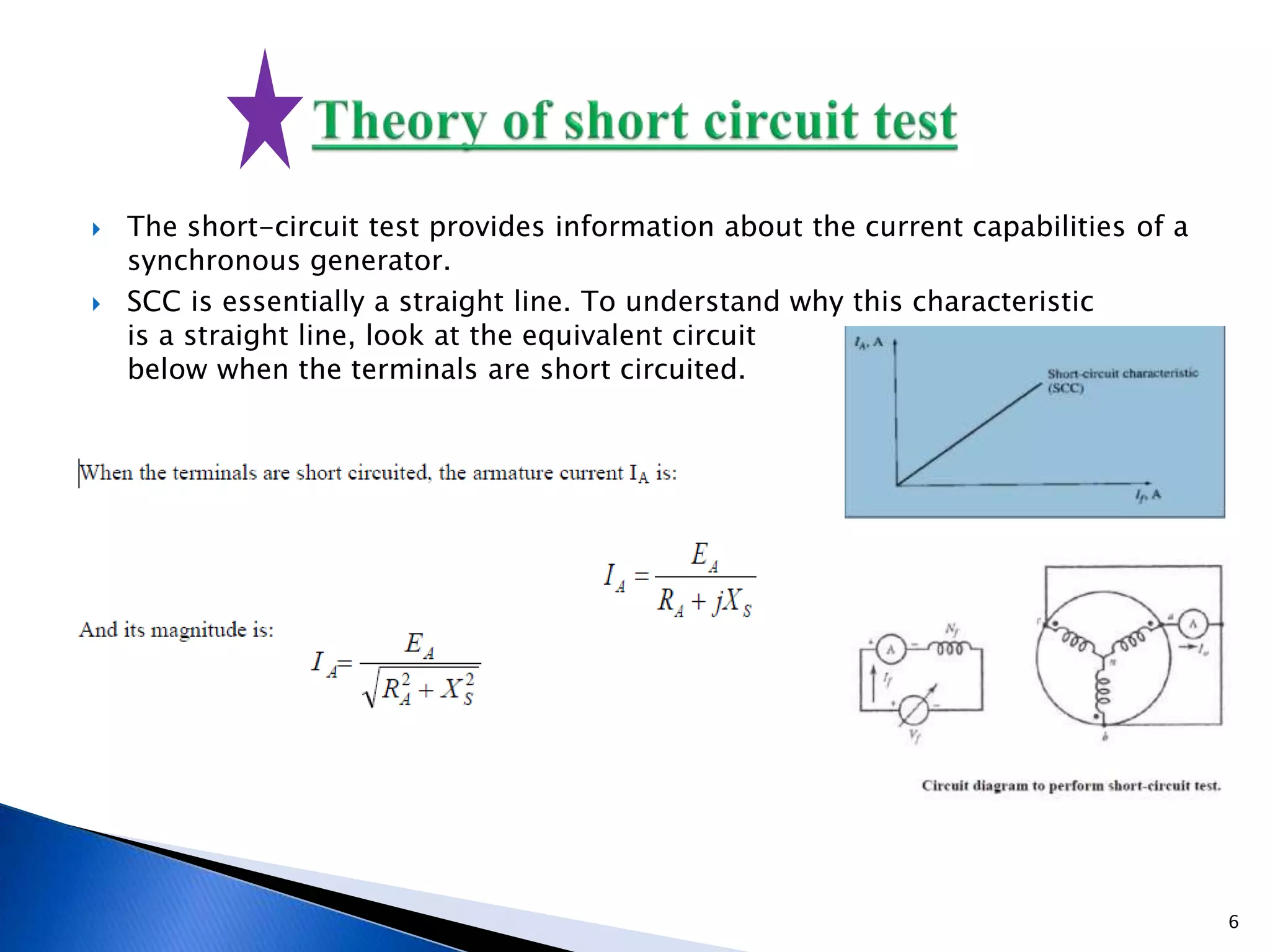
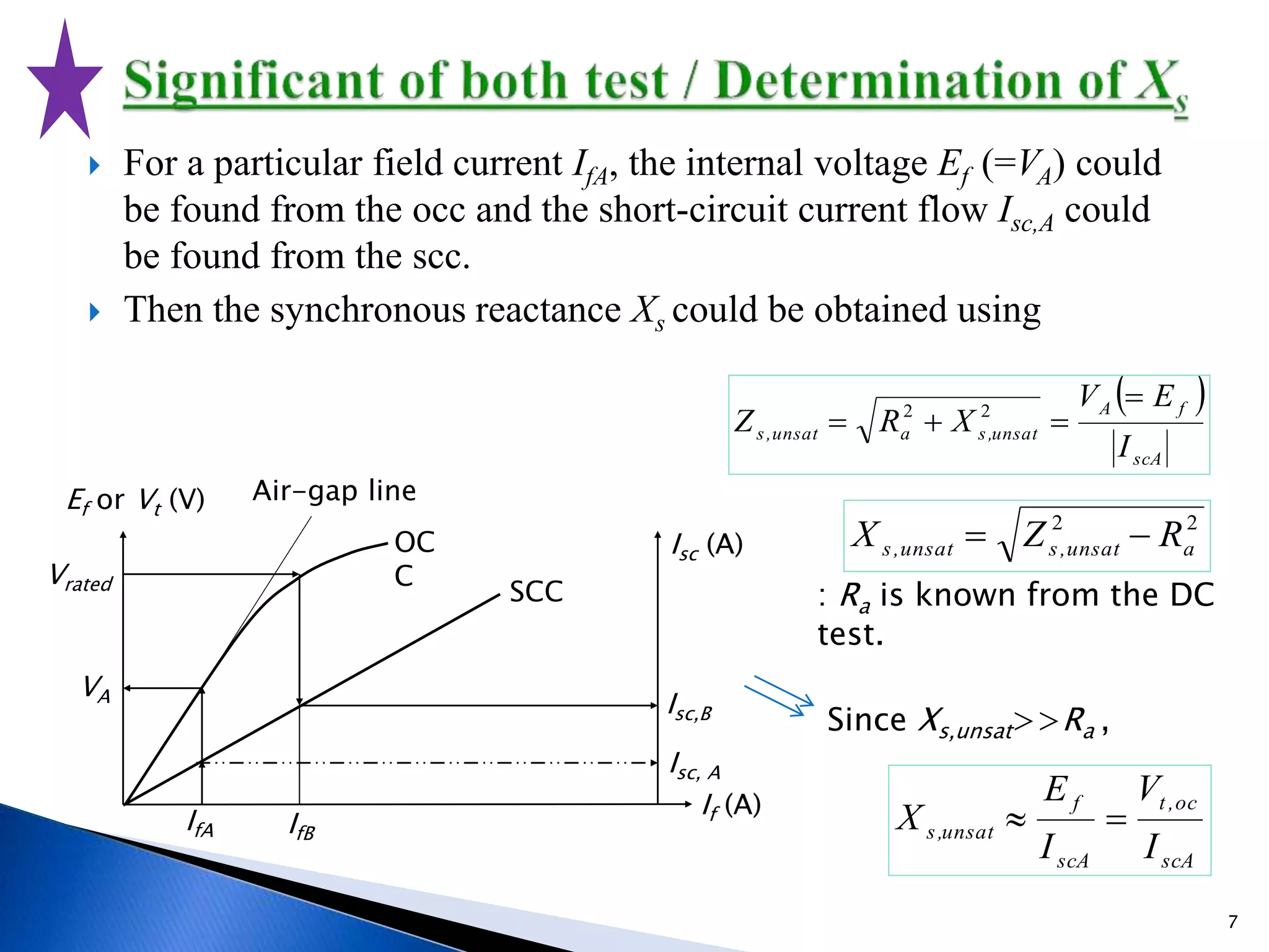
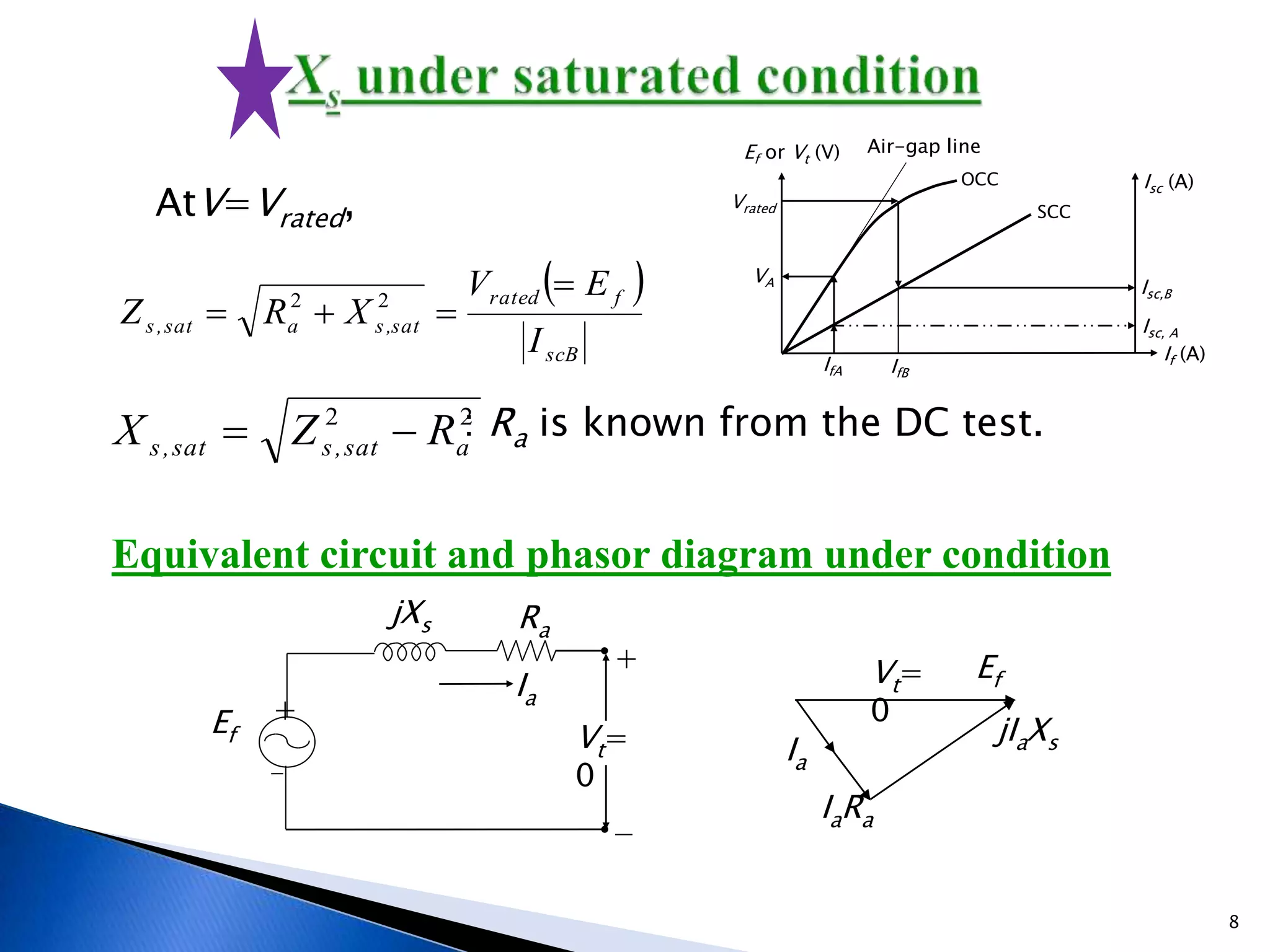
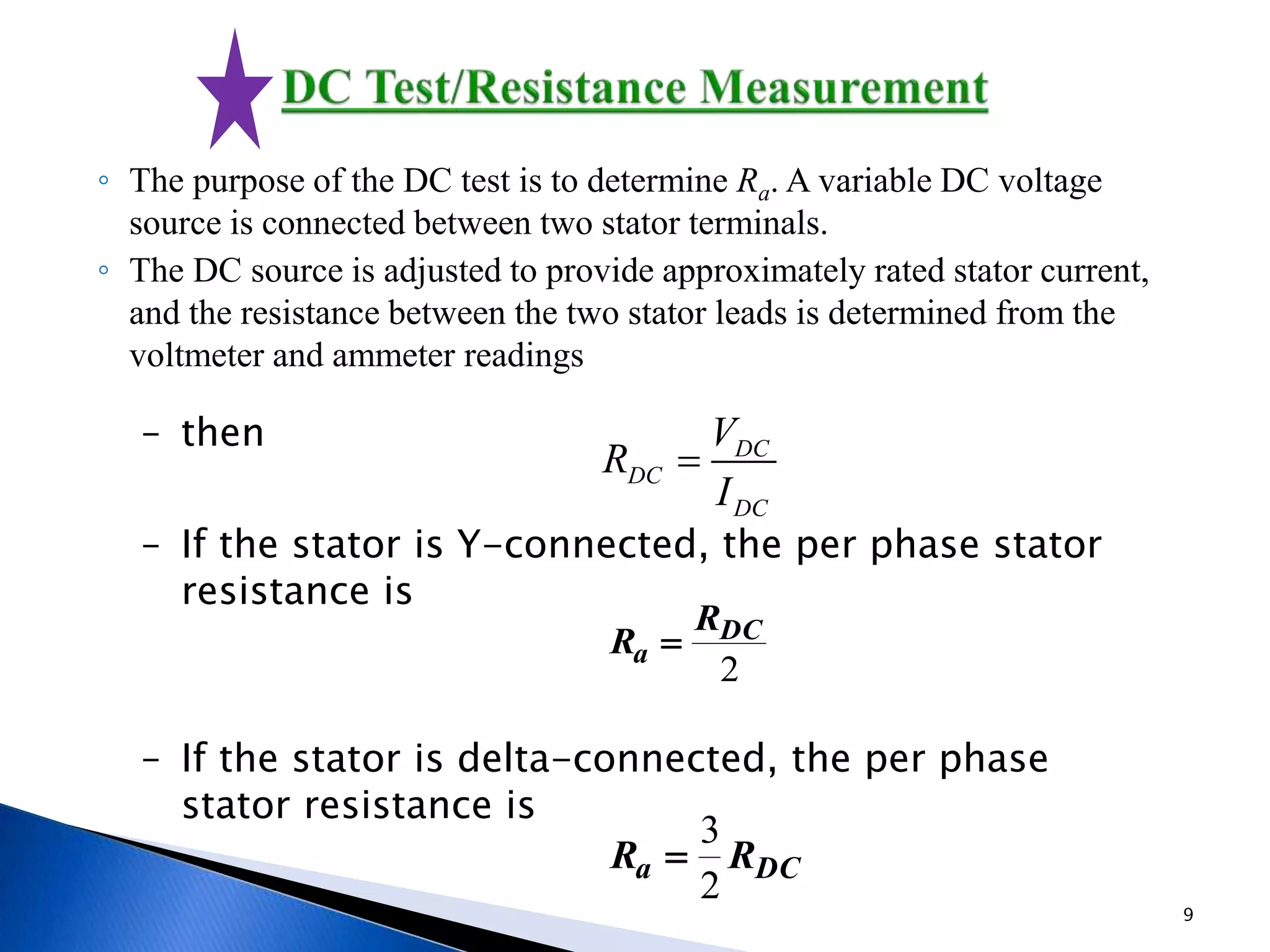
ID-021-131-088
Section-B
1
2
 The equivalent circuit of a synchronous generator that has been derived
contains three quantities that must be determined in order to completely
describe the behaviour of a real synchronous generator:
◦ The saturation characteristic: relationship between If and f (and
therefore between If and Ef)
◦ The synchronous reactance ,Xs
◦ The armature resistance ,Ra
 The above three quantities could be determined by performing the
following three tests:
◦ Open-circuit test
◦ Short-circuit test
◦ DC test
◦ Open Circuit and Short Circuit tests on a synchronous generator
in order to determine its synchronous impedance.
3
 The open-circuit test, or the no-load test , The open circuit test
is carried out with the terminals of the machine disconnected
from any external circuit.
 With the terminals open, IA=0, so EA= Vφ. It is thus possible to
construct a plot of EA or VT vs IF graph. This plot is called open-
circuit characteristic (OCC) of a generator. With this
characteristic, it is possible to find the internal generated
voltage of the generator for any given field current.
 If the machine is wye connected, the measure voltage will be a
line-line voltage and the per-phase induced voltage can be
found from
 Remember from the armature windings note that the induced
voltage vs. field current plot will have a similar shape to the flux
vs. field current plot.
4
In the plot above, the air gap line (dotted blue) gives the
relationship between mmf and flux density in the air gap.
(Induced voltage is proportional to flux density). At higher
field current levels, the iron in the machine saturates and
the percentage of field mmf applied to the air gap is
reduced. As a result the induced voltage falls below the
air gap line.
As synchronous machines operate at effectively
constant speed, the open circuit voltage test provides the
relationship between field current and induced voltage
for all load conditions. The induced open circuit voltage is
sometimes known as the "excitation voltage", or even
simply as the "excitation".
5
 The short-circuit test provides information about the current capabilities of a
synchronous generator.
 SCC is essentially a straight line. To understand why this characteristic
is a straight line, look at the equivalent circuit
below when the terminals are short circuited.
6
 For a particular field current IfA, the internal voltage Ef (=VA) could
be found from the occ and the short-circuit current flow Isc,A could
be found from the scc.
 Then the synchronous reactance Xs could be obtained using
IfA
Ef or Vt (V) Air-gap line
OC
C
Isc (A)
SCC
If (A)
Vrated
VA
Isc,B
Isc, A
IfB
 
scA
fA
unsat,saunsat,s
I
EV
XRZ

 22
22
aunsat,sunsat,s RZX 
scA
oc,t
scA
f
unsat,s
I
V
I
E
X 
: Ra is known from the DC
test.
Since Xs,unsat>>Ra ,
7
Ia
Ef Vt=
0
jXs Ra
+
+
EfVt=
0
jIaXs
IaRa
Ia
 
scB
frated
sat,sasat,s
I
EV
XRZ

 22
AtV=Vrated,
22
asat,ssat,s RZX  : Ra is known from the DC test.
Equivalent circuit and phasor diagram under condition
IfA
Ef or Vt (V) Air-gap line
OCC Isc (A)
SCC
If (A)
Vrated
VA Isc,B
Isc, A
IfB
8
– then
– If the stator is Y-connected, the per phase stator
resistance is
– If the stator is delta-connected, the per phase
stator resistance is
◦ The purpose of the DC test is to determine Ra. A variable DC voltage
source is connected between two stator terminals.
◦ The DC source is adjusted to provide approximately rated stator current,
and the resistance between the two stator leads is determined from the
voltmeter and ammeter readings
DC
DC
DC
V
R
I

2
DC
a
R
R 
DCa RR
2
3

9
10
11
 Synchronous Reactance (in a generator analysis domain) is and
equivalent series per-phase inductance term (think per-phase
winding resistance) and is mainly composed of the machine's per-
phase leakage inductance (equivalent series inductance of primary
and secondary flux leakage) and armature reaction (distortion in flux
introduced by an armature current in a machine, once again on a
per-phase basis; described as a series inductance).
L_SyncReac=L_leakage+L_ArmatureReaction. That sort of touches
the surface of synchronous reactance.
12
13

Synchronous Generator Loading Characteristics

  • 1.
  • 2.
  • 3.
     The equivalentcircuit of a synchronous generator that has been derived contains three quantities that must be determined in order to completely describe the behaviour of a real synchronous generator: ◦ The saturation characteristic: relationship between If and f (and therefore between If and Ef) ◦ The synchronous reactance ,Xs ◦ The armature resistance ,Ra  The above three quantities could be determined by performing the following three tests: ◦ Open-circuit test ◦ Short-circuit test ◦ DC test ◦ Open Circuit and Short Circuit tests on a synchronous generator in order to determine its synchronous impedance. 3
  • 4.
     The open-circuittest, or the no-load test , The open circuit test is carried out with the terminals of the machine disconnected from any external circuit.  With the terminals open, IA=0, so EA= Vφ. It is thus possible to construct a plot of EA or VT vs IF graph. This plot is called open- circuit characteristic (OCC) of a generator. With this characteristic, it is possible to find the internal generated voltage of the generator for any given field current.  If the machine is wye connected, the measure voltage will be a line-line voltage and the per-phase induced voltage can be found from  Remember from the armature windings note that the induced voltage vs. field current plot will have a similar shape to the flux vs. field current plot. 4
  • 5.
    In the plotabove, the air gap line (dotted blue) gives the relationship between mmf and flux density in the air gap. (Induced voltage is proportional to flux density). At higher field current levels, the iron in the machine saturates and the percentage of field mmf applied to the air gap is reduced. As a result the induced voltage falls below the air gap line. As synchronous machines operate at effectively constant speed, the open circuit voltage test provides the relationship between field current and induced voltage for all load conditions. The induced open circuit voltage is sometimes known as the "excitation voltage", or even simply as the "excitation". 5
  • 6.
     The short-circuittest provides information about the current capabilities of a synchronous generator.  SCC is essentially a straight line. To understand why this characteristic is a straight line, look at the equivalent circuit below when the terminals are short circuited. 6
  • 7.
     For aparticular field current IfA, the internal voltage Ef (=VA) could be found from the occ and the short-circuit current flow Isc,A could be found from the scc.  Then the synchronous reactance Xs could be obtained using IfA Ef or Vt (V) Air-gap line OC C Isc (A) SCC If (A) Vrated VA Isc,B Isc, A IfB   scA fA unsat,saunsat,s I EV XRZ   22 22 aunsat,sunsat,s RZX  scA oc,t scA f unsat,s I V I E X  : Ra is known from the DC test. Since Xs,unsat>>Ra , 7
  • 8.
    Ia Ef Vt= 0 jXs Ra + + EfVt= 0 jIaXs IaRa Ia  scB frated sat,sasat,s I EV XRZ   22 AtV=Vrated, 22 asat,ssat,s RZX  : Ra is known from the DC test. Equivalent circuit and phasor diagram under condition IfA Ef or Vt (V) Air-gap line OCC Isc (A) SCC If (A) Vrated VA Isc,B Isc, A IfB 8
  • 9.
    – then – Ifthe stator is Y-connected, the per phase stator resistance is – If the stator is delta-connected, the per phase stator resistance is ◦ The purpose of the DC test is to determine Ra. A variable DC voltage source is connected between two stator terminals. ◦ The DC source is adjusted to provide approximately rated stator current, and the resistance between the two stator leads is determined from the voltmeter and ammeter readings DC DC DC V R I  2 DC a R R  DCa RR 2 3  9
  • 10.
  • 11.
  • 12.
     Synchronous Reactance(in a generator analysis domain) is and equivalent series per-phase inductance term (think per-phase winding resistance) and is mainly composed of the machine's per- phase leakage inductance (equivalent series inductance of primary and secondary flux leakage) and armature reaction (distortion in flux introduced by an armature current in a machine, once again on a per-phase basis; described as a series inductance). L_SyncReac=L_leakage+L_ArmatureReaction. That sort of touches the surface of synchronous reactance. 12
  • 13.