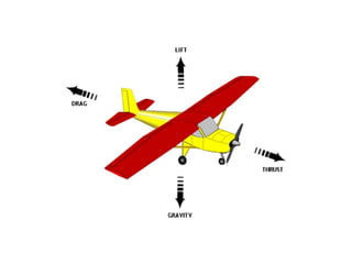
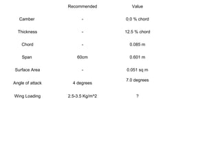
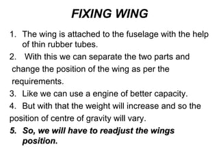
The document provides information on the control surfaces and aerodynamic components of an aircraft. It discusses that elevators control pitch, ailerons control roll, and the rudder controls yaw. It also mentions vertical and horizontal stabilizers provide stability and prevent pitching and yawing motions. The document further provides details on requirements, wing design and construction, airfoils, servos, engines, batteries, and tips for stability.
Introduction to Radio Controlled PlanesMostafa Eid
This is an introductory for beginners who do not know where to start or how to start, so this comprehensive session states the major types of RC Aircrafts which shall allow you to search deeply in one or all of these categories
Nomenclature and classification of controls in an airplane (slide # 3-4).
Which are the aerodynamic forces acting on airplane (slide # 5).
Working principle of an airplane (slide # 6).
How an airplane flies (basic motions of an airplane) (slide # 7).
How controls play their roles in these motions (slide # 8-22).
Simulate a flight in Cessna Skyhawk (slide # 23-28).
References and Questions & answers (slide # 30).
This Powerpoint Presentation reviews on the topic - Aeroplane and Its Parts (With aerodynamics).
It was made for Educational Purpose.
If anyone want source file, E-mail:- moideenthashreef@hotmail.com
Performance Evaluation of 830kW Wind Turbine and an Analysis of Various Param...Rohan Raibagkar
The project aimed at
1) Understanding the performance of wind power project of 830KW
2) Determining system reliability (Grid availability, Machine availability, System availability) and
operating hours of the wind conversion system from the data obtained at site
3) Analyzing the effect of various parameters like velocity, blade length, temperature, pressure, air
density on the power generation of a wind turbine
4) Forecasting or Predicting the performance of the wind turbine generators based on the above
parameters
This analysis can be used to existing sites which are nearby the above evaluated wind power project for Maximizing power generation
It helps us to understand effect of various parameters viz. air density, air pressure, air temperature, blade length, velocity on the power generation
According to the results, there is a high effect of air characteristics on the mechanical power.
The environment’s parameter has a massive effect on the generated power, which will lead the researchers to concentrate on it with highest priority
Complete one year data was used for the analysis of the wind power project
Results were executed using Matlab
Ocean Thermal Energy Conversion SystemsNaveen Kumar
OTEC or OCEAN THERMAL ENERGY CONVERSION, is a renewable energy technology that converts solar radiation to electric power by use of the world oceans. The use of OTEC as a source of electricity will help reduce the state’s almost complete dependence on imported fossil fuels. About one fourth of the 1.7 * 1013 watts of solar energy reaching the earth’s atmosphere is absorbed by sea water. OTEC can be considered as an indirect solar technology because the surface water are warmed by the sun. OTEC can also be used to produce ammonia, hydrogen, aluminium, chlorine and other chemicals.
Ocean Thermal Energy Conversion (OTEC) is a marine renewable energy technology that converts solar radiation to electrical power by the temperature difference between the deep cold ocean water and warm tropical surface water.
Until we know that large wind turbines/mills to generate electricity. But the technology advanced such that these wind turbines came to our home for our domestical use. In this ppt I discussed about new small residential wind turbines by which we can reduce our electrical bills and more. Have a look!
Luis Vega from the National Marine Renewable Energy Center describes the technical and economic aspects of Ocean Thermal Energy Conversion (OTEC). Slides from the REIS seminar series at the University of Hawaii at Manoa on 2009-10-01.
Renewable energy is generally electricity supplied from sources, such as wind power, solar power,
geothermal energy, hydro power and various forms of biomass. The popularity of renewable energy
has experienced a significant upsurge in recent times due to the exhaustion of conventional power
generation methods and increasing realization of its adverse effects on the environment. Wind energy
has been harnessed for centuries but it has only emerged as a major part of our energy solution quite
recently and this report focus on utilizing wind energy by using vertical axis wind turbine.
Key Takeaways
Helicopters take advantage of free stream flow along a rotor blade to produce lift and thrust.
The blades on a helicopter’s main rotor have an angle of attack, which plays the same role as a wing in an airplane.
The tail rotor is responsible for stabilizing the helicopter so that it does not rotate under torque from the rotor.
Helicopter aerodynamics
The correspondence between helicopter aerodynamics and airplane aerodynamics spans beyond the need for free stream flow across an airfoil. Helicopter aerodynamics involves the same forces that arise in airplane aerodynamics, but these forces arise in different ways due to fluid flow across the aircraft. In this article, we’ll look more at the basics of how a helicopter generates its lift and thrust with only a single main rotor as well as how the design of the rotor influences helicopter aerodynamics.
Overview of Helicopter Aerodynamics
All helicopters have two rotors that generate the lift and thrust required to steer the aircraft as well as stabilize the helicopter against unwanted rotation. Attached to the engine are the main rotor blades, which rotate against the surrounding air to produce a flow along each rotor blade. Technically, a helicopter’s rotor blades are a set of airfoils, and they can produce lift in the same way as the wing on a fixed-wing aircraft.
A helicopter’s main rotor interacts with the surrounding airflow to manipulate the main aerodynamic forces in the following manner:
Lift: As the rotor blade spins, airflow across the bottom of the rotor blade produces lift to counteract gravity.
Gravity: Obviously a helicopter does not manipulate gravity, but by exerting just enough lift to counteract gravity, the helicopter can hover at a fixed altitude.
Thrust: Unlike fixed-wing aircraft or jets, thrust is not produced by the engine directly. Instead, the rotor is tilted, which orients the lift vector away from the vertical direction.
Drag: As the helicopter moves, airflow across the body creates drag due to the formation of a boundary layer.
It should be clear as to the function of the main rotor: to provide lift and thrust, depending on the relative orientation of the rotor blades and the body. We can now dig a bit deeper into the function provided by each of these elements in helicopter aerodynamics.
Angle of Attack and Tilt on the Rotor Blades
The role of the rotor is two-fold: it converts lift into thrust and it needs to generate lift. The former is accomplished by tilting the rotor using the cyclic pitch control while the latter is determined by the angle of attack of the rotor blades and the length of each rotor blade. Larger blades, faster rotation, and an appropriate angle of attack can produce maximal lift on the helicopter during flight.
During flight, the oncoming free air stream will imbalance the lift provided by the rotor, which will create a rolling motion. This is balanced by designing the rotor to have flapping blades, meaning the blades can natur
The International Journal of Engineering & Science is aimed at providing a platform for researchers, engineers, scientists, or educators to publish their original research results, to exchange new ideas, to disseminate information in innovative designs, engineering experiences and technological skills. It is also the Journal's objective to promote engineering and technology education. All papers submitted to the Journal will be blind peer-reviewed. Only original articles will be published.
The papers for publication in The International Journal of Engineering& Science are selected through rigorous peer reviews to ensure originality, timeliness, relevance, and readability.
The Micro-Heat exchangers are heat exchangers in which fluids flows in very confined area such as tubes or small cavities whose dimensions are below 1mm in size. They also go by others name as Micro scale heat exchangers, micro channel heat exchangers, micro structure heat exchanger. They comprises of numerous parallel but relatively short micro channels for the passage of fluid flow. Their ability to handle high heat flux densities to control precise chemical reactions or cool the high-end computer processors is becoming more and more relevant to their efficient and safe operation.The Micro-Heat exchangers are heat exchangers in which fluids flows in very confined area such as tubes or small cavities whose dimensions are below 1mm in size. They also go by others name as Micro scale heat exchangers, micro channel heat exchangers, micro structure heat exchanger. They comprises of numerous parallel but relatively short micro channels for the passage of fluid flow. Their ability to handle high heat flux densities to control precise chemical reactions or cool the high-end computer processors is becoming more and more relevant to their efficient and safe operation.
Mechanics & Process Variable Involved in Cigarette ProductionZubair Ahmed
¬¬Hence a brief introduction on the components of the cigarette production unit was studied and analyzed. With the brief information an attempt to solve a problem statement “Increasing productivity of LOGA 5” was undertaken. The steps taken were proved to be effective in their course of action. Further deep study into the machinery would aim to remove all the existing problems. During the course of internship, basic knowledge of management skills were learned. Also the importance of finely structured work and work distribution was felt.
A short paper on Bionics and its implications.
For the people without disability, technology makes things easier and for the people with disability, technology makes things possible.
Overview of the fundamental roles in Hydropower generation and the components involved in wider Electrical Engineering.
This paper presents the design and construction of hydroelectric dams from the hydrologist’s survey of the valley before construction, all aspects and involved disciplines, fluid dynamics, structural engineering, generation and mains frequency regulation to the very transmission of power through the network in the United Kingdom.
Author: Robbie Edward Sayers
Collaborators and co editors: Charlie Sims and Connor Healey.
(C) 2024 Robbie E. Sayers
Hybrid optimization of pumped hydro system and solar- Engr. Abdul-Azeez.pdffxintegritypublishin
Advancements in technology unveil a myriad of electrical and electronic breakthroughs geared towards efficiently harnessing limited resources to meet human energy demands. The optimization of hybrid solar PV panels and pumped hydro energy supply systems plays a pivotal role in utilizing natural resources effectively. This initiative not only benefits humanity but also fosters environmental sustainability. The study investigated the design optimization of these hybrid systems, focusing on understanding solar radiation patterns, identifying geographical influences on solar radiation, formulating a mathematical model for system optimization, and determining the optimal configuration of PV panels and pumped hydro storage. Through a comparative analysis approach and eight weeks of data collection, the study addressed key research questions related to solar radiation patterns and optimal system design. The findings highlighted regions with heightened solar radiation levels, showcasing substantial potential for power generation and emphasizing the system's efficiency. Optimizing system design significantly boosted power generation, promoted renewable energy utilization, and enhanced energy storage capacity. The study underscored the benefits of optimizing hybrid solar PV panels and pumped hydro energy supply systems for sustainable energy usage. Optimizing the design of solar PV panels and pumped hydro energy supply systems as examined across diverse climatic conditions in a developing country, not only enhances power generation but also improves the integration of renewable energy sources and boosts energy storage capacities, particularly beneficial for less economically prosperous regions. Additionally, the study provides valuable insights for advancing energy research in economically viable areas. Recommendations included conducting site-specific assessments, utilizing advanced modeling tools, implementing regular maintenance protocols, and enhancing communication among system components.
COLLEGE BUS MANAGEMENT SYSTEM PROJECT REPORT.pdfKamal Acharya
The College Bus Management system is completely developed by Visual Basic .NET Version. The application is connect with most secured database language MS SQL Server. The application is develop by using best combination of front-end and back-end languages. The application is totally design like flat user interface. This flat user interface is more attractive user interface in 2017. The application is gives more important to the system functionality. The application is to manage the student’s details, driver’s details, bus details, bus route details, bus fees details and more. The application has only one unit for admin. The admin can manage the entire application. The admin can login into the application by using username and password of the admin. The application is develop for big and small colleges. It is more user friendly for non-computer person. Even they can easily learn how to manage the application within hours. The application is more secure by the admin. The system will give an effective output for the VB.Net and SQL Server given as input to the system. The compiled java program given as input to the system, after scanning the program will generate different reports. The application generates the report for users. The admin can view and download the report of the data. The application deliver the excel format reports. Because, excel formatted reports is very easy to understand the income and expense of the college bus. This application is mainly develop for windows operating system users. In 2017, 73% of people enterprises are using windows operating system. So the application will easily install for all the windows operating system users. The application-developed size is very low. The application consumes very low space in disk. Therefore, the user can allocate very minimum local disk space for this application.
Event Management System Vb Net Project Report.pdfKamal Acharya
In present era, the scopes of information technology growing with a very fast .We do not see any are untouched from this industry. The scope of information technology has become wider includes: Business and industry. Household Business, Communication, Education, Entertainment, Science, Medicine, Engineering, Distance Learning, Weather Forecasting. Carrier Searching and so on.
My project named “Event Management System” is software that store and maintained all events coordinated in college. It also helpful to print related reports. My project will help to record the events coordinated by faculties with their Name, Event subject, date & details in an efficient & effective ways.
In my system we have to make a system by which a user can record all events coordinated by a particular faculty. In our proposed system some more featured are added which differs it from the existing system such as security.
Courier management system project report.pdfKamal Acharya
It is now-a-days very important for the people to send or receive articles like imported furniture, electronic items, gifts, business goods and the like. People depend vastly on different transport systems which mostly use the manual way of receiving and delivering the articles. There is no way to track the articles till they are received and there is no way to let the customer know what happened in transit, once he booked some articles. In such a situation, we need a system which completely computerizes the cargo activities including time to time tracking of the articles sent. This need is fulfilled by Courier Management System software which is online software for the cargo management people that enables them to receive the goods from a source and send them to a required destination and track their status from time to time.
Quality defects in TMT Bars, Possible causes and Potential Solutions.PrashantGoswami42
Maintaining high-quality standards in the production of TMT bars is crucial for ensuring structural integrity in construction. Addressing common defects through careful monitoring, standardized processes, and advanced technology can significantly improve the quality of TMT bars. Continuous training and adherence to quality control measures will also play a pivotal role in minimizing these defects.
Water scarcity is the lack of fresh water resources to meet the standard water demand. There are two type of water scarcity. One is physical. The other is economic water scarcity.
Forklift Classes Overview by Intella PartsIntella Parts
Discover the different forklift classes and their specific applications. Learn how to choose the right forklift for your needs to ensure safety, efficiency, and compliance in your operations.
For more technical information, visit our website https://intellaparts.com
7. Vertical and Horizontal Stabilizer
•The stabilizer is a fixed wing section whose job is to
provide stability for the aircraft, to keep it flying
straight.
•Horizontal Stabilizer: The horizontal stabilizer
prevents up-and-down, or pitching, motion of the
aircraft nose.
•Vertical Stabilizer: The vertical stabilizer prevents
side-to-side, or yawing, motion of the aircraft nose.
8. Aerodynamic Controls
• Elevators: control pitch angle
• Ailerons: control roll angle
• Rudder: controls yaw angle
• Flaps: increase lift and drag
• Leading edge slats: increase lift
• Drag brakes: increase drag
• Spoilers: reduce lift and increase drag
10. Styrofoam Usage
Similar to thermoCole, though smaller grain
size.
Easier and faster to work on compared to
balsa.
Can we wire cut to get the wing in one
piece.
Needs proper strengthening by use of balsa
and tape.
11. STYROFOAM WINGSTYROFOAM WING
•The foam is cut with a hot wire cutter.
Finished with sand paper.
•Strengthened by providing wooden spar or
Carbon Fiber rod (you can use other
materials also).
•Taping is done to the whole wing surface in
the span wise direction.
12.
13. Aspect Ratio
• it’s the ratio of wings length to its breadth
• Wing span^2 / area of planform
Wing Span
Plan Form
The distance between
One tip of the wing to
Other end.
Wing planform is
The silhouette of
The wing when
viewed
From above
14. High AR means ???
•narrow wing,
•Leading to less drag
•helps in stability at low speeds
•Low roll
Calculating Area of Planform???
elevator and rudder their area too is to be included in the area
of the tail and vertical stabilizer respectively
15. FUSELAGE
1. Everything is attached to fuselage: Wings, motor/engine,
battery/ fuel-tank, servos, other electrical components,
etc.
2. Must have proper strength at proper place. More
strength at the front than the tail.
3. Servo arms, control rods should not clash with each
other.
16. 4 Should have proper space for the servos,
5 battery receiver, esc, etc.
Fuselage lenght – 70-75 % of wing span.
17. MonoWing
High Wing Configuration
• Shorter Landing Distance
• Greater Stability at lower speeds
Moderate Tapered Wings
•Good Stall characteristics
•Straight Edge
•Wings narrow towards tip
Wing Sweep –Straight
Wing is right angled to line
Of flight
•Common for low speed
18. 2.5kg/sq m –3.3 kg/ sq m
wing loading is the loaded weight of
the aircraft divided by the area of the
wing.
Wing Loading
Position of Ailerons
25% of the wing area
19. Airfoil
Airfoil Shape
Camber = 0.0 % chord , = 12.5 % chord ,
Chord = 0.085 m , Span = 0.601 m ,
Surface Area = 0.051 sq m ,
Angle of attack = 7.0 degrees ,
Tested on Following
Specified Conditions
Altitude = 60 m ,
Density = 1.163kg/cu m
Pressure = 101.261kPa,
Temperature = 30C,
Airspeed = 10 km/hr ,
Lift = 0.19 NewtonsLift = 0.19 Newtons
Drag = 0 NewtonsDrag = 0 Newtons
Coeff of lift 0.823Coeff of lift 0.823
Coeff of Drag 0.076Coeff of Drag 0.076
21. 1. These are responsible for controls of aero models.
2. The control surfaces –ailerons, elevators, engine
throttle and rudders are connected to the servos using
push rods .
3. All servos are connected to
receiver.
4. Rotation of servos(torque) on receiving signal from
transmitter causes the movements of control parts.
5. Defined by the torque
they provide.
22. Stabilizers
The edges of the aileron were rounded to
minimize drag effect.
Vertical stabilizer 50% of HS
23.
24. Engine
1. Engine mount is first fixed to the front of
fuselage using nuts and bolts.
2. Engine is attached to the mount.
25. Recommended Value
Camber - 0.0 % chord
Thickness - 12.5 % chord
Chord - 0.085 m
Span 60cm 0.601 m
Surface Area - 0.051 sq m
Angle of attack 4 degrees
7.0 degrees
Wing Loading 2.5-3.5 Kg/m^2 ?
26. Propellers
• Have diameter and pitch usually written in the
form Diameter X pitch. D X P
• Pitch is the distance moved by the propeller in
one revolution under ideal conditions.
• High pitch propeller generally provides more
speed than a low one.
• Propellers can be double or triple blade.
• Distance moved by an ideal propeller = pitch *
RPM
27. Motor
kv rating: It is the revolutions/volt.
For ex: 1000 kv will give 1000 rpm at one volt.
So if the voltage of battery is 12 V then the RPM is
1000 X 12 = 12000 rpm.
The rpm is the function of voltage only and irrespective of propeller size or pitch.
Power: It is the power supplied by the battery given by volt X current. Propeller size, ESC
and voltage & power ratings are given in specification.
Choice of propeller, motor depend on the thrust required
28. BATTERY
• Lithium Ion Batteries used
for aero modeling purposes.
• Number of cells in a battery is denoted by S rating.
Eg3S = 3 cells in series.
• Rated as 1300mAh, 1600mAh, etc
• C rating gives the maximum discharge that it can produce. Eg1000mAh with 20C
implies maximum current of 20 Amp.
• Maximum current=Rating in Amp Hr X C rating
29. landing gears
the part where Landing Gear have to be mounted must be very strong,
so that it can take up the vibrations at the time of landing.
30. FINDING THE POSITION OF WING
• One of the most important thing is to find a
suitable position for the wing.
• For if the centre of gravity of the entire system is
not in between the aerodynamic centre and the tail
then the plane will not be stable.
• We try to keep the position of centre of gravity at
a distance of 0.1c to 0.2c from the aerodynamic
centre.
• The aerodynamic centre is located at a distance
of 0.25c (approximately) from the leading edge
ofthe wing for subsonic speeds.
31. FIXING WING
1. The wing is attached to the fuselage with the help
of thin rubber tubes.
2. With this we can separate the two parts and
change the position of the wing as per the
requirements.
3. Like we can use a engine of better capacity.
4. But with that the weight will increase and so the
position of centre of gravity will vary.
5.5. So, we will have to readjust the wingsSo, we will have to readjust the wings
position.position.
33. MORE TIPS…
•Try to increase the dihedral angle gradually, in the spanwise directions.
•Small winglet-type structures reduce drag.
•MINIMIZE WEIGHT AS MUCH AS POSSIBLE!!!
•Reduction in chord along spanwise direction (high aspect ratio) might
increase Glide Ratio.
•Round all leading edges in your model.
•Reduction in fuselage cross section.