This document discusses various concepts related to aircraft structural design and airworthiness requirements. It describes how aircraft structure is divided into primary, secondary, and tertiary categories based on their importance. Primary structure, if failed, could cause loss of control or structural collapse. Examples provided stress the importance of withstanding forces like tension, compression, shear, bending, and torsion to ensure structural integrity and safety. Station identification systems are also covered to precisely locate structural components through methods like station numbering and zoning.
![AIRWORTHINESS REQUIREMENTS
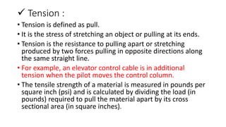
FOR STRUCTURAL STRENGTH :
• An aircraft is airworthy "when it meets its type design and is in a
condition for safe operation" [FAA]
• The goal is to only allow aircraft meeting established minimum
standards to fly in an attempt to safeguard aircrews and the general
public.
• Other requirements for weights, ventilation, factors of safety and
even door operation are included.](https://image.slidesharecdn.com/ppt21-201020041456/85/Ppt-2-1-2-320.jpg)
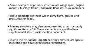
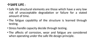
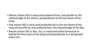
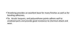
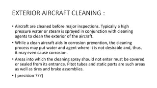
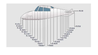
![• To locate structures to the right or left of the center line of an aircraft,
a similar method is employed. Many manufacturers consider the
center line of the aircraft to be a zero station from which
measurements can be taken to the right or left to locate an airframe
member.
• Fuselage stations (Fus. Sta. or FS) are numbered in inches from a
reference or zero point known as the reference datum. [Figure ]
• The reference datum is an imaginary vertical plane at or near the
nose of the aircraft from which all fore and aft distances are
measured.
• The distance to a given point is measured in inches parallel to a
center line extending through the aircraft from the nose through the
center of the tail cone.](https://image.slidesharecdn.com/ppt21-201020041456/85/Ppt-2-1-16-320.jpg)
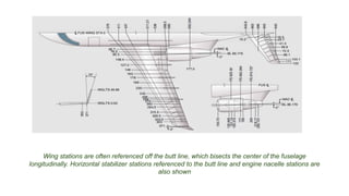
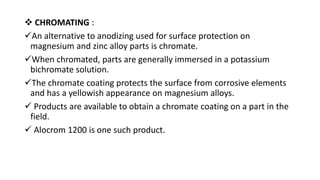
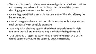
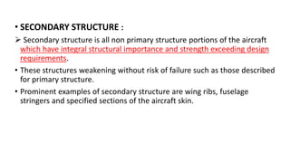
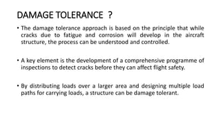
![• Buttock line or butt line (BL) is a vertical reference plane down the
center of the aircraft from which measurements left or right can be
made. [Figure ]](https://image.slidesharecdn.com/ppt21-201020041456/85/Ppt-2-1-18-320.jpg)
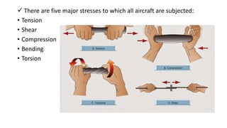
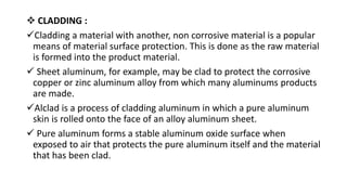
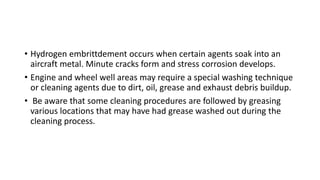
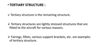
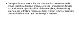
![Water line (WL) is the measurement of height in inches perpendicular
from a horizontal plane usually located at the ground, cabin floor, or
some other easily referenced location. [Figure 3]
Figure 3. Water line diagram](https://image.slidesharecdn.com/ppt21-201020041456/85/Ppt-2-1-19-320.jpg)