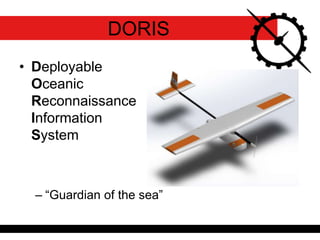
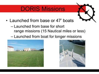
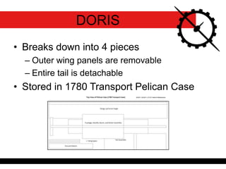
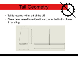
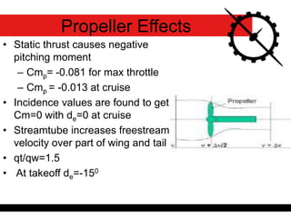
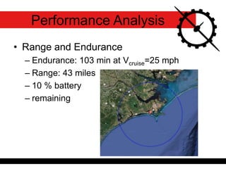
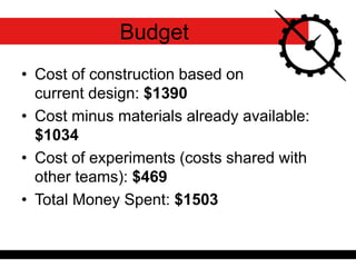
DORIS Critical Design Review
Team 2
Jacob Edwards – Team Leader
Clint Shook
Kyle Maready
Paris McGee
Kevin Kight
James Nardi
Kara Brody
Sean Maguire
Aaron McCullough
• Deployable
Oceanic
Reconnaissance
Information
System
– “Guardian of the sea”
DORIS
DORIS
• Launched from base or 47’ boats
– Launched from base for short
range missions (15 Nautical miles or less)
– Launched from boat for longer missions
DORIS Missions
• Breaks down into 4 pieces
– Outer wing panels are removable
– Entire tail is detachable
• Stored in 1780 Transport Pelican Case
DORIS
• Outer wing sections are attached by
sliding spar into slot on wing
• Latches then hold the wing in the y-
direction
• Tail attaches using pin lock
Assembly
• Retrieved from water using boat
hooks to grab hook on forward boom
Retrieval Ring
• Red LED – Left Wing Tip
• Green LED – Right Wing Tip
• White LED – Tail
• Wired to switch on fuselage
LED Configuration
Cree, Inc. SMD Full-Color
• Red (619 – 624 nm)
• Red LED Brightness
(560 – 1120 lumens)
• Green (520 – 540 nm)
• Green LED Brightness
(1120 – 2240 lumens)
Fuselage Layout
• Due to use of flaperons, high cambered
airfoil is unnecessary for initial hand launch
• 2412 and 3412 were
compared
– Both yielded similar
3D results
• 2412 chosen
Airfoil Selection
• Tail is located 46 in. aft of the LE
• Sizes determined from iterations conducted to find Level
1 handling
Tail Geometry
• Static thrust causes negative
pitching moment
– Cmp= -0.081 for max throttle
– Cmp = -0.013 at cruise
• Incidence values are found to get
Cm=0 with de=0 at cruise
• Streamtube increases freestream
velocity over part of wing and tail
• qt/qw=1.5
• At takeoff de=-150
Propeller Effects
Drag Calculations
• Buildup methods based on wetted
surface area and Cf
• Results
– CD,0=0.031 (Datcom)
– CD,0=0.034 (Torenbeek)
• Using more conservative value of 0.034
• Range and Endurance
– Endurance: 103 min at Vcruise=25 mph
– Range: 43 miles
– 10 % battery
– remaining
Performance Analysis
• Critical Speeds
– Stall: 17.6 mph
– Climb: 41 mph at 1230 ft./min
– Maneuver: 43 mph
– Maximum: 67 mph
– Best Glide: 24 mph at -4.9o
– Approach: 21.1 mph
V∞
• Take-off
– Accelerate to 15 ft./s before release
– Accelerate to Vclimb = 41 mph and rotate to
climb angle of 20o
– Hand Launch Trajectory
Performance Analysis
0 5 10 15 20 25 30
-5
-4
-3
-2
-1
0
distance (ft.)
height(ft.)
• Landing
– Descend from cruise
altitude to 100 ft. at best
glide slope.
– Descend at -9o from
horizon from 100 ft. to
landing.
– Circular Approach with
Radius of 40 ft. and bank
angle of 37o
– Approach at 1.2Vstall
Performance Analysis
-40
-20
0
20
40
-50
0
50
-50
0
50
100
150
x = feet
Landing - DORIS
y = feet
z=altitude
100
150
50
Landing Pattern
• Turn Performance
– Maximum bank angle and Minimum turn
radius as function of velocity
Performance Analysis
0
10
20
30
40
50
60
70
80
90
17 27 37 47
MaxBankAngle(degrees)
V (mph)
0
20
40
60
80
100
120
0 20 40 60 80
Radius(ft.)
Velocity (mph)
Motor:
Propulsion System
Scorpion SII-3020-1110
•Motor Kv: 1110 RPM/Volt
•Max Continuous Current: 60
Amps
•Max Continuous Power: 840
Watts
Castle Creations Phoenix Lite 75
Max Amps: 75 amps*
5 amps BEC
Max Volts: 25 volts
6S LiPo
4x ThunderPower RC
3900mAh 3S
• Motor attaches to a fabricated boom
cap
• Boom cap attaches to boom with screw
Motor Attachment
• Propeller designed for is a 12” x 8”
folding propeller
• Verified by propeller matching experiment
to refine propeller
choice
• Test Ranges 12” x 6”
to 13” x 7”
12” x 8” folding propeller
Propeller
• Based on full 2 lb payload and 0.5 lb
autopilot weights
Weight Build Up
Weight (lb)
Fuselage (Empty) 1.25
Carbon Fiber Tail
Boom 1.00
Wing 2.29
Tail 0.56
Batteries 2.40
Autopilot 0.50
Motor 0.37
Payload 2.00
Prop 0.06
ESC 0.14
Totals 10.6
Structural Analysis
• Fuselage Strength
– Design for loads of 6g and
-2g with a factor of safety
of 1.5
– Test all internal weights
(Payload, Autopilot, etc.)
– Test normal landing loads,
bad landing loads, and rogue
wave loads
• Wing Strength
– Flight loads of 6g and -2g with a factor of safety of 1.5
-3
-2
-1
0
1
2
3
4
5
6
7
0 20 40 60 80 100
n(g's)
Airspeed (mph)
V-n Diagram
stall
stall
structural damage
structural damage
ANSYS Calculations
• ANSYS calculations were performed on the
following aircraft structures to test for
structural integrity:
– Wing
• Wing Load Cases
• Fixed Wing Connection
– Fuselage and Nacelle
• Flight Load Cases
• Central wing ribs in model fixed
Wing deflection at max load
Stress and Deformation
• 9g Wing Load
– 38.6 ksi
– 1.435 in
• 9g Fuselage Load
– 1306 psi
– 0.0033 in
Stress and Deformation
• 50 lb Force on
Nose Section
– 2319 psi
– 0.0089 in
• 20 lb Force applied
to Fuselage and
Nacelle Side
– 5185 psi
– 0.0162 in
• Current rib structure supporting
the wing
• Rest of structure made of foam
Wing Structure
• Based on Clβ which is equal to -0.066
at cruise
• Effective dihedral at cruise is 5.5̊
• Effective dihedral at takeoff is 10.2̊
Effective Dihedral
Effective Dihedral vs. Geometric Dihedral
Handling Qualities at Cruise
u0 = 39.6 ft/s
θ0 = 0°
Category B Handling Requirements
Dynamic Mode η wn (rad/s) ζ Thalf/double (s) τR Level
Short Period
Oscillation -7.512 9.268 0.8106 0.0922 Level 1
Phugoid -0.0620 0.8052 0.0770 11.18 Level 1
Dutch Roll -1.047 4.774 0.2194 0.6618 Level 1
Roll -23.08 0.0300 0.0433 Level 1
Spiral 0.0088 78.75 Level 1
Handling Qualities at Takeoff
u0 = 30.93 ft/s
θ0 = 0°
Category C Handling Requirements
Dynamic Mode η wn (rad/s) ζ Thalf/double (s) τR Level
Short Period
Oscillation -5.900 8.059 0.7321 0.1175 Level 1
Phugoid -0.0008 1.183 0.0007 866.3 Level 2
Dutch Roll -1.114 5.498 0.2027 0.6219 Level 2
Roll -16.67 0.0416 0.059985 Level 1
Spiral 0.0221 31.357 Level 1
Handling Qualities at Landing
Dynamic Mode η wn (rad/s) ζ Thalf/double (s) τR Level
Short Period
Oscillation -5.775 7.884 0.7325 0.1200 Level 1
Phugoid -0.0543 1.190 0.0456 12.76 Level 1
Dutch Roll -1.495 4.825 0.3097 0.4637 Level 2
Roll -16.70 0.0415 0.0599 Level 1
Spiral 0.0558 12.42 Level 1
u0 = 31 ft/s
θ0 = -9.1°
Category C Handling Requirements
Control Powers
Control Powers
Flight Research
Standard Actual
Control
Surface Size
Max
Deflection
Pitch Rate Δq/Δδe -4/sec -6.397/sec
Elevator Power δα/dδe -1.5 -1.6 2" x 24" 20°
Aileron Power 1.25 rev/sec 1.122 rev/sec 2" x 28" 20°
Rudder Power δβ/dδr 1 0.85 3" x 12" 20°
• Match control effectiveness at
Design CG
• When flaps deployed, aileron
deflection limited
• The aft CG limit is based on dynamic
stability handling qualities
• Design CG: 33.8 % mac or 5.72 in from LE
for a static margin
of 12%
• Aft CG limit: 43 %
mac or 7 in from LE
• Forward CG limit:
27.3 % 4.8 in from LE
CG Limits
• Autopilot mounted to door with hinges
• Slides in like a drawer and rear of autopilot
locks into place in rear bulkhead
• Door is screwed into
forward bulkhead and
forms seal with a gasket
Autopilot
• All the wires run to the servos will be
braided 20 gauge wire.
• The tail and flaperons will have common ground
and power.
• Will have waterproof quick connects at wing and
tail connections
• The power and ground leads will be split again
for the lights that will be located on the wings
and the tail.
Wiring
• The payload will slide in the front of
the fuselage on a rail system
• Camera looks through
cutout in the bottom
of the fuselage and
provides full field of
vision for the camera
Imagery Payload
Waterproofing Plans
• Structure
– Fiberglass/resin is fairly waterproof on its own
but long exposure to water will call for marine
polyurethane paint
– Wood will be coated in a water-based
polyurethane paint
– Wing connections sealed with gaskets
• Internals
– Payload will be waterproof
– Autopilot box will be located in sealed
compartment in rear of fuselage
– Batteries will have connections waterproofed
Waterproofing Plans
• Openings
– Payload/Battery hatch
• Sealed with a large O-ring around opening
– Antenna/wire protrusions sealed with epoxy.
Waterproofing Plans
Nose Cone O-Ring
• E0540-80 Ethylene Propylene Rubber
• Shore Hardness: 60
• 21 inch length
• Requires 10.5 lbs force to
achieve seal
• Seal achieved by screwing
wing nut onto nose cap
• Cost of construction based on
current design: $1390
• Cost minus materials already available:
$1034
• Cost of experiments (costs shared with
other teams): $469
• Total Money Spent: $1503
Budget
Questions?

Team2_CDR_Final

  • 1.
    DORIS Critical DesignReview Team 2 Jacob Edwards – Team Leader Clint Shook Kyle Maready Paris McGee Kevin Kight James Nardi Kara Brody Sean Maguire Aaron McCullough
  • 2.
  • 3.
  • 4.
    • Launched frombase or 47’ boats – Launched from base for short range missions (15 Nautical miles or less) – Launched from boat for longer missions DORIS Missions
  • 5.
    • Breaks downinto 4 pieces – Outer wing panels are removable – Entire tail is detachable • Stored in 1780 Transport Pelican Case DORIS
  • 6.
    • Outer wingsections are attached by sliding spar into slot on wing • Latches then hold the wing in the y- direction • Tail attaches using pin lock Assembly
  • 7.
    • Retrieved fromwater using boat hooks to grab hook on forward boom Retrieval Ring
  • 8.
    • Red LED– Left Wing Tip • Green LED – Right Wing Tip • White LED – Tail • Wired to switch on fuselage LED Configuration Cree, Inc. SMD Full-Color • Red (619 – 624 nm) • Red LED Brightness (560 – 1120 lumens) • Green (520 – 540 nm) • Green LED Brightness (1120 – 2240 lumens)
  • 9.
  • 10.
    • Due touse of flaperons, high cambered airfoil is unnecessary for initial hand launch • 2412 and 3412 were compared – Both yielded similar 3D results • 2412 chosen Airfoil Selection
  • 11.
    • Tail islocated 46 in. aft of the LE • Sizes determined from iterations conducted to find Level 1 handling Tail Geometry
  • 12.
    • Static thrustcauses negative pitching moment – Cmp= -0.081 for max throttle – Cmp = -0.013 at cruise • Incidence values are found to get Cm=0 with de=0 at cruise • Streamtube increases freestream velocity over part of wing and tail • qt/qw=1.5 • At takeoff de=-150 Propeller Effects
  • 13.
    Drag Calculations • Buildupmethods based on wetted surface area and Cf • Results – CD,0=0.031 (Datcom) – CD,0=0.034 (Torenbeek) • Using more conservative value of 0.034
  • 14.
    • Range andEndurance – Endurance: 103 min at Vcruise=25 mph – Range: 43 miles – 10 % battery – remaining Performance Analysis
  • 15.
    Performance Analysis • CriticalSpeeds – Stall: 17.6 mph – Climb: 41 mph at 1230 ft./min – Maneuver: 43 mph – Maximum: 67 mph – Best Glide: 24 mph at -4.9o – Approach: 21.1 mph V∞
  • 16.
    • Take-off – Accelerateto 15 ft./s before release – Accelerate to Vclimb = 41 mph and rotate to climb angle of 20o – Hand Launch Trajectory Performance Analysis 0 5 10 15 20 25 30 -5 -4 -3 -2 -1 0 distance (ft.) height(ft.)
  • 17.
    • Landing – Descendfrom cruise altitude to 100 ft. at best glide slope. – Descend at -9o from horizon from 100 ft. to landing. – Circular Approach with Radius of 40 ft. and bank angle of 37o – Approach at 1.2Vstall Performance Analysis -40 -20 0 20 40 -50 0 50 -50 0 50 100 150 x = feet Landing - DORIS y = feet z=altitude 100 150 50 Landing Pattern
  • 18.
    • Turn Performance –Maximum bank angle and Minimum turn radius as function of velocity Performance Analysis 0 10 20 30 40 50 60 70 80 90 17 27 37 47 MaxBankAngle(degrees) V (mph) 0 20 40 60 80 100 120 0 20 40 60 80 Radius(ft.) Velocity (mph)
  • 19.
    Motor: Propulsion System Scorpion SII-3020-1110 •MotorKv: 1110 RPM/Volt •Max Continuous Current: 60 Amps •Max Continuous Power: 840 Watts Castle Creations Phoenix Lite 75 Max Amps: 75 amps* 5 amps BEC Max Volts: 25 volts 6S LiPo 4x ThunderPower RC 3900mAh 3S
  • 20.
    • Motor attachesto a fabricated boom cap • Boom cap attaches to boom with screw Motor Attachment
  • 21.
    • Propeller designedfor is a 12” x 8” folding propeller • Verified by propeller matching experiment to refine propeller choice • Test Ranges 12” x 6” to 13” x 7” 12” x 8” folding propeller Propeller
  • 22.
    • Based onfull 2 lb payload and 0.5 lb autopilot weights Weight Build Up Weight (lb) Fuselage (Empty) 1.25 Carbon Fiber Tail Boom 1.00 Wing 2.29 Tail 0.56 Batteries 2.40 Autopilot 0.50 Motor 0.37 Payload 2.00 Prop 0.06 ESC 0.14 Totals 10.6
  • 23.
    Structural Analysis • FuselageStrength – Design for loads of 6g and -2g with a factor of safety of 1.5 – Test all internal weights (Payload, Autopilot, etc.) – Test normal landing loads, bad landing loads, and rogue wave loads • Wing Strength – Flight loads of 6g and -2g with a factor of safety of 1.5 -3 -2 -1 0 1 2 3 4 5 6 7 0 20 40 60 80 100 n(g's) Airspeed (mph) V-n Diagram stall stall structural damage structural damage
  • 24.
    ANSYS Calculations • ANSYScalculations were performed on the following aircraft structures to test for structural integrity: – Wing • Wing Load Cases • Fixed Wing Connection – Fuselage and Nacelle • Flight Load Cases • Central wing ribs in model fixed Wing deflection at max load
  • 25.
    Stress and Deformation •9g Wing Load – 38.6 ksi – 1.435 in • 9g Fuselage Load – 1306 psi – 0.0033 in
  • 26.
    Stress and Deformation •50 lb Force on Nose Section – 2319 psi – 0.0089 in • 20 lb Force applied to Fuselage and Nacelle Side – 5185 psi – 0.0162 in
  • 27.
    • Current ribstructure supporting the wing • Rest of structure made of foam Wing Structure
  • 28.
    • Based onClβ which is equal to -0.066 at cruise • Effective dihedral at cruise is 5.5̊ • Effective dihedral at takeoff is 10.2̊ Effective Dihedral Effective Dihedral vs. Geometric Dihedral
  • 29.
    Handling Qualities atCruise u0 = 39.6 ft/s θ0 = 0° Category B Handling Requirements Dynamic Mode η wn (rad/s) ζ Thalf/double (s) τR Level Short Period Oscillation -7.512 9.268 0.8106 0.0922 Level 1 Phugoid -0.0620 0.8052 0.0770 11.18 Level 1 Dutch Roll -1.047 4.774 0.2194 0.6618 Level 1 Roll -23.08 0.0300 0.0433 Level 1 Spiral 0.0088 78.75 Level 1
  • 30.
    Handling Qualities atTakeoff u0 = 30.93 ft/s θ0 = 0° Category C Handling Requirements Dynamic Mode η wn (rad/s) ζ Thalf/double (s) τR Level Short Period Oscillation -5.900 8.059 0.7321 0.1175 Level 1 Phugoid -0.0008 1.183 0.0007 866.3 Level 2 Dutch Roll -1.114 5.498 0.2027 0.6219 Level 2 Roll -16.67 0.0416 0.059985 Level 1 Spiral 0.0221 31.357 Level 1
  • 31.
    Handling Qualities atLanding Dynamic Mode η wn (rad/s) ζ Thalf/double (s) τR Level Short Period Oscillation -5.775 7.884 0.7325 0.1200 Level 1 Phugoid -0.0543 1.190 0.0456 12.76 Level 1 Dutch Roll -1.495 4.825 0.3097 0.4637 Level 2 Roll -16.70 0.0415 0.0599 Level 1 Spiral 0.0558 12.42 Level 1 u0 = 31 ft/s θ0 = -9.1° Category C Handling Requirements
  • 32.
    Control Powers Control Powers FlightResearch Standard Actual Control Surface Size Max Deflection Pitch Rate Δq/Δδe -4/sec -6.397/sec Elevator Power δα/dδe -1.5 -1.6 2" x 24" 20° Aileron Power 1.25 rev/sec 1.122 rev/sec 2" x 28" 20° Rudder Power δβ/dδr 1 0.85 3" x 12" 20° • Match control effectiveness at Design CG • When flaps deployed, aileron deflection limited
  • 33.
    • The aftCG limit is based on dynamic stability handling qualities • Design CG: 33.8 % mac or 5.72 in from LE for a static margin of 12% • Aft CG limit: 43 % mac or 7 in from LE • Forward CG limit: 27.3 % 4.8 in from LE CG Limits
  • 34.
    • Autopilot mountedto door with hinges • Slides in like a drawer and rear of autopilot locks into place in rear bulkhead • Door is screwed into forward bulkhead and forms seal with a gasket Autopilot
  • 35.
    • All thewires run to the servos will be braided 20 gauge wire. • The tail and flaperons will have common ground and power. • Will have waterproof quick connects at wing and tail connections • The power and ground leads will be split again for the lights that will be located on the wings and the tail. Wiring
  • 36.
    • The payloadwill slide in the front of the fuselage on a rail system • Camera looks through cutout in the bottom of the fuselage and provides full field of vision for the camera Imagery Payload
  • 37.
    Waterproofing Plans • Structure –Fiberglass/resin is fairly waterproof on its own but long exposure to water will call for marine polyurethane paint – Wood will be coated in a water-based polyurethane paint – Wing connections sealed with gaskets
  • 38.
    • Internals – Payloadwill be waterproof – Autopilot box will be located in sealed compartment in rear of fuselage – Batteries will have connections waterproofed Waterproofing Plans
  • 39.
    • Openings – Payload/Batteryhatch • Sealed with a large O-ring around opening – Antenna/wire protrusions sealed with epoxy. Waterproofing Plans
  • 40.
    Nose Cone O-Ring •E0540-80 Ethylene Propylene Rubber • Shore Hardness: 60 • 21 inch length • Requires 10.5 lbs force to achieve seal • Seal achieved by screwing wing nut onto nose cap
  • 41.
    • Cost ofconstruction based on current design: $1390 • Cost minus materials already available: $1034 • Cost of experiments (costs shared with other teams): $469 • Total Money Spent: $1503 Budget
  • 42.

Editor's Notes

  • #3 This brings us to our current state. DORIS is the name of our UAV. It stands for Deployable Oceanic Reconaissance Information System. This name was chosen because Doris was a goddess in Greek mythology who was a guardian of the sea. DORIS will help the Coast Guard accomplish their mission of keeping the sea and its surrounding areas safe.
  • #5 DORIS will be capable of 2 length missions. For short range missions that would be completed with the 25’ boats, it would be launched from the office and fly to its destination, complete its mission, and return to base or be retrieved from the 25’ boat. For long range missions, it can be launched from the 47’ boats once it is closer to its target. From there it can complete its mission and return to the launching boat for retrieval.
  • #6 To be easily stored aboard both the 25’ and 47’ boat, the plane will break down and fit inside a watertight pelican case. On the 25’ boat it will be stored up front by the front door. On the 47’ boat it can be stored in the forward storage compartment below deck. From there it can be passed up through the hatch to one of the other 4-6 crew members.
  • #7 Next the outer sections are connected by sliding the carbon fiber spar into the receptacle slightly and plugging in the electrical connections. When the wings are brought fully together, they are secured by two latches as shown. There is also a tab on not shown here that keeps the wing from twisting.
  • #10 The fuselage layout shown here allows for easy access to payload and batteries. Our batteries are designed to be easily swappable. It would be possible for boats to carry spare sets of charged batteries to switch out when necessary and extend the usefulness of the plane. This layout also allows us to place the payload under the CG to allow for minimum change for different payload configurations.
  • #16 These are the current specifications for our plane.
  • #24 Structural analysis has begun on all the portions of the plane. These 3 areas, the fuselage strength, wing attachment and boom, will be important areas with high stress.
  • #38 Since the UAV will operate in a marine environment and land in water, waterproofing is an important aspect of this plane. We have taken this into consideration and will implement some of these strategies. For the structure, most of the skin will be made of fiberglass/resin which is generally waterproof. However since it will be consistently in the water, we may need to implement additional strategies. Gel coatings like those used on boats, marine polyurethane paint, sun curable resin and polyurethane foam used in surfboards.
  • #40 Some aspects of the UAV may utilize wood. While there should be no exposed wood, if needed polyurethane finish or tung oil may be used. Silicon may also be used as a waterproofing agent and it also protects against UV rays. Since the UAV will be used near or in the ocean, protection against saltwater corrosion has been taken into consideration.