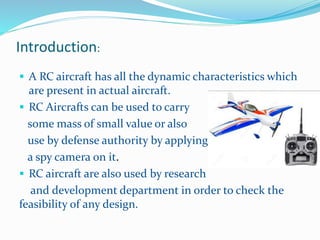
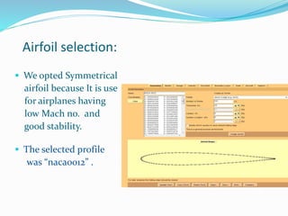
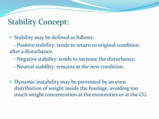
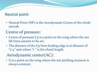
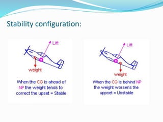
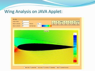
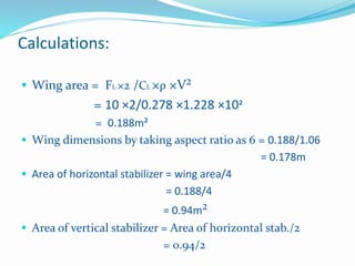
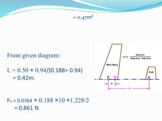
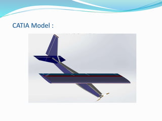
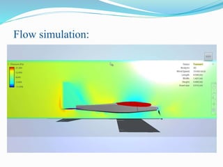
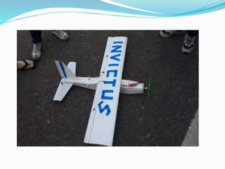
Roopal Raj
Sandeep Kr. Mishra
Shreya Srivastava
6th B
Introduction:
 A RC aircraft has all the dynamic characteristics which
are present in actual aircraft.
 RC Aircrafts can be used to carry
some mass of small value or also
use by defense authority by applying
a spy camera on it.
 RC aircraft are also used by research
and development department in order to check the
feasibility of any design.
Airfoil:
 An airfoil is the 2D cross-section shape of the wing,
which creates sufficient lift with minimal drag.
 Types:
 Flat bottom airfoil
 Semi-Symmetric airfoil
 Symmetrical airfoil
Terminology
Airfoil selection:
 We opted Symmetrical
airfoil because It is use
for airplanes having
low Mach no. and
good stability.
 The selected profile
was “naca0012” .
Lift
• The component of the total aerodynamic force of an airfoil that is
perpendicular to the relative wind.
Drag
• The component of the total aero –
dynamic force of an airfoil that is
parallel to the relative wind.
FL = CL ρ A
v²/2
FD = CD ρ A
v²/2
Motion Characteristics
Control Surfaces :
Ailerons:
 An aileron is a hinged flight control
surface usually attached to the trailing
arm of each wing of a fixed-wing
aircraft.
 Movement around this axis is called
'rolling' or 'banking'.
Rudder:
 The rudder are hinged on rear
surface, making as a vertical stabilizer.
and its area is half of the whole vertical
stabilizer.
Elevators:
 The elevators are hinged on rear
surface, making as a whole a tail
plane or horizontal stabilizer.
Stability Concept:
 Stability may be defined as follows:
- Positive stability: tends to return to original condition
after a disturbance.
- Negative stability: tends to increase the disturbance.
- Neutral stability: remains at the new condition.
 Dynamic instability may be prevented by an even
distribution of weight inside the fuselage, avoiding too
much weight concentration at the extremities or at the CG.
Neutral point:
 Neutral Point (NP) is the Aerodynamic Centre of the whole
aircraft.
Centre of pressure:
 Centre of pressure Cp is a point on the wing where the net
lift force assume to be act.
 The distance of the Cp from leading edge is at distance of
“c/4” unit where “c ” is the chord length.
Aerodynamic center(AC):
 It is a point on the wing where the net pitching moment is
always constant.
Stability configuration:
Wing Analysis on JAVA Applet:
Calculations:
 Wing area = FL ×2 /CL ×ρ ×V²
= 10 ×2/0.278 ×1.228 ×10²
= 0.188m²
 Wing dimensions by taking aspect ratio as 6 = 0.188/1.06
= 0.178m
 Area of horizontal stabilizer = wing area/4
= 0.188/4
= 0.94m²
 Area of vertical stabilizer = Area of horizontal stab./2
= 0.94/2
= 0.47m²
From given diagram:
L = 0.50 × 0.94/(0.188+ 0.94)
= 0.42m.
FD = 0.0764 × 0.188 ×10 ×1.228/2
= 0.861 N
CATIA Model :
Flow simulation:
 John J. Bertin “Aerodynamics for Engineers”
Fourth Edition U.S Air force Academy.
 John D. Anderson “Introduction to flight
Dynamics” Third edition.
 Wikipedia
 Softwares used :
- JAVA Applet
- Flow design
- CATIA V5
Reference:
Mini project on RC plane

Mini project on RC plane

  • 1.
    Roopal Raj Sandeep Kr.Mishra Shreya Srivastava 6th B
  • 2.
    Introduction:  A RCaircraft has all the dynamic characteristics which are present in actual aircraft.  RC Aircrafts can be used to carry some mass of small value or also use by defense authority by applying a spy camera on it.  RC aircraft are also used by research and development department in order to check the feasibility of any design.
  • 3.
    Airfoil:  An airfoilis the 2D cross-section shape of the wing, which creates sufficient lift with minimal drag.  Types:  Flat bottom airfoil  Semi-Symmetric airfoil  Symmetrical airfoil
  • 4.
  • 5.
    Airfoil selection:  Weopted Symmetrical airfoil because It is use for airplanes having low Mach no. and good stability.  The selected profile was “naca0012” .
  • 6.
    Lift • The componentof the total aerodynamic force of an airfoil that is perpendicular to the relative wind. Drag • The component of the total aero – dynamic force of an airfoil that is parallel to the relative wind. FL = CL ρ A v²/2 FD = CD ρ A v²/2
  • 7.
  • 8.
    Control Surfaces : Ailerons: An aileron is a hinged flight control surface usually attached to the trailing arm of each wing of a fixed-wing aircraft.  Movement around this axis is called 'rolling' or 'banking'.
  • 9.
    Rudder:  The rudderare hinged on rear surface, making as a vertical stabilizer. and its area is half of the whole vertical stabilizer. Elevators:  The elevators are hinged on rear surface, making as a whole a tail plane or horizontal stabilizer.
  • 10.
    Stability Concept:  Stabilitymay be defined as follows: - Positive stability: tends to return to original condition after a disturbance. - Negative stability: tends to increase the disturbance. - Neutral stability: remains at the new condition.  Dynamic instability may be prevented by an even distribution of weight inside the fuselage, avoiding too much weight concentration at the extremities or at the CG.
  • 11.
    Neutral point:  NeutralPoint (NP) is the Aerodynamic Centre of the whole aircraft. Centre of pressure:  Centre of pressure Cp is a point on the wing where the net lift force assume to be act.  The distance of the Cp from leading edge is at distance of “c/4” unit where “c ” is the chord length. Aerodynamic center(AC):  It is a point on the wing where the net pitching moment is always constant.
  • 12.
  • 13.
    Wing Analysis onJAVA Applet:
  • 14.
    Calculations:  Wing area= FL ×2 /CL ×ρ ×V² = 10 ×2/0.278 ×1.228 ×10² = 0.188m²  Wing dimensions by taking aspect ratio as 6 = 0.188/1.06 = 0.178m  Area of horizontal stabilizer = wing area/4 = 0.188/4 = 0.94m²  Area of vertical stabilizer = Area of horizontal stab./2 = 0.94/2
  • 15.
    = 0.47m² From givendiagram: L = 0.50 × 0.94/(0.188+ 0.94) = 0.42m. FD = 0.0764 × 0.188 ×10 ×1.228/2 = 0.861 N
  • 16.
  • 17.
  • 19.
     John J.Bertin “Aerodynamics for Engineers” Fourth Edition U.S Air force Academy.  John D. Anderson “Introduction to flight Dynamics” Third edition.  Wikipedia  Softwares used : - JAVA Applet - Flow design - CATIA V5 Reference: