Download to read offline


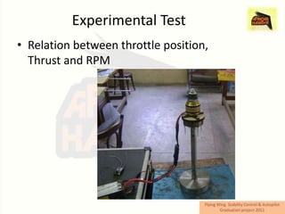
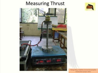
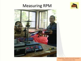

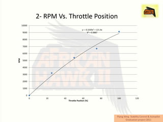


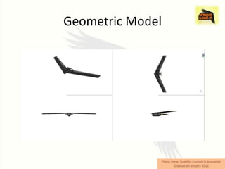


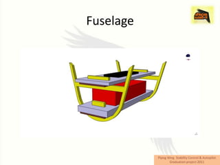
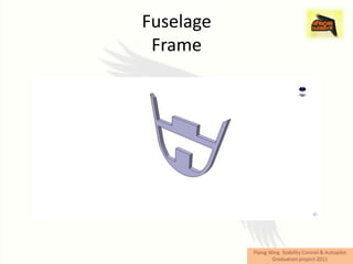


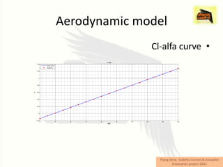


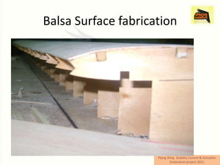

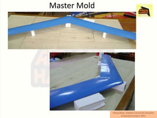
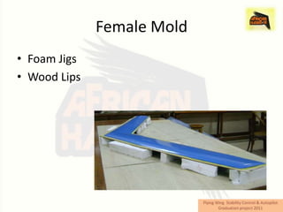
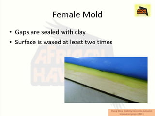


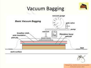


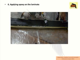


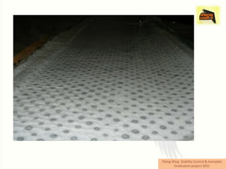

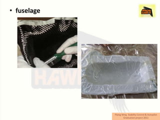

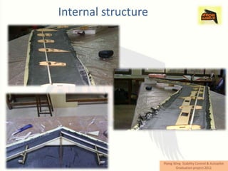


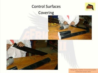
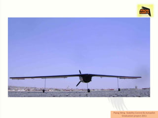


This document provides an overview of the African Hawk II unmanned aerial vehicle project completed by three students. It describes the objectives of modeling and manufacturing the aircraft and installing an autopilot system. Updates from previous models include changes to the internal arrangement, landing gear, use of vacuum bagging in manufacturing, and the MicroPilot autopilot. Test results are presented relating throttle position to thrust, RPM, endurance, and aircraft velocity. The manufacturing process is also summarized, including mold making, vacuum bagging of composite surfaces, and installation of control surfaces.


![[Files.indowebster.com] carburator tuning](https://cdn.slidesharecdn.com/ss_thumbnails/files-indowebster-com-carburatortuning-130416214917-phpapp01-thumbnail.jpg?width=640&height=640&fit=bounds)


