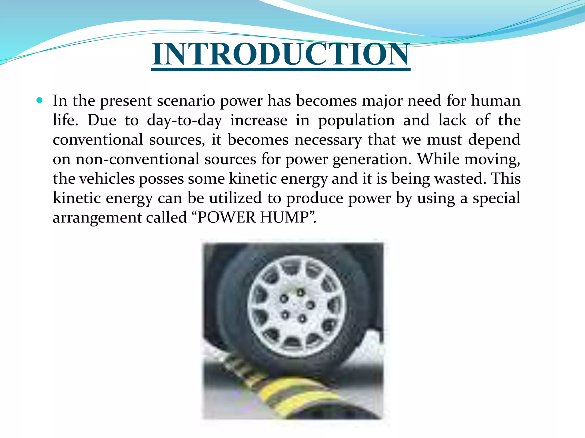
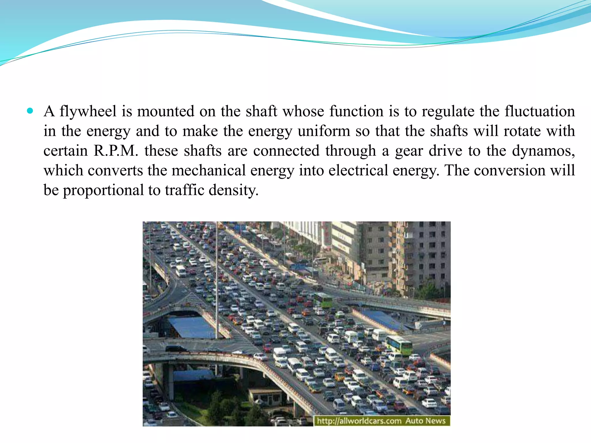
POWER GENERATION FROM SPEED
BREAKERS
SUBMITTED BY:
Digvijay pal(1473720014)
Saurabh mishra(1473720033)
Vishal verma (1473720048)
RAJKIYA ENGINEERING COLLEGE,
AMBEDKARNAGAR
GUIDED BY:
Mr. Sonu Kumar
Department Of Electrical Engineering
CONTENTS
 Introduction
 Objective
 Basic Principle
 Block diagram
 Advantages
 Disadvantages
 Futures scope
 Conclusion
 References
INTRODUCTION
 In the present scenario power has becomes major need for human
life. Due to day-to-day increase in population and lack of the
conventional sources, it becomes necessary that we must depend
on non-conventional sources for power generation. While moving,
the vehicles posses some kinetic energy and it is being wasted. This
kinetic energy can be utilized to produce power by using a special
arrangement called “POWER HUMP”.
OBJECTIVE
 The objective for doing this step is to reduce the crises of
electricity. why we only depend upon any thermal power plant
,or hydro power plants etc.
 To generate power at low cost.
 As per MW generation, it impose Rs 10 million but from other
source such as hydro and thermal ,the cost is 8 times higher.
Different Mechanism
There are 4 types of mechanisms to implement this method of
producing electricity. They are as follows:
• Rack-Pinion Mechanism
• Crank-Shaft Mechanism
• Roller Mechanism
• Spring Coil Mechanism
BASIC PRINCIPLE
 The kinetic energy of moving vehicle can be utilized to produce power by using
a special arrangement called POWER HUMP.
 It is an Electro-Mechanical unit. It utilizes both mechanical technologies and
electrical techniques for the power generation and its storage.
 POWER HUMP is a dome like device likely to be speed breaker.
 Whenever the vehicle is allowed to pass over the dome it gets pressed
downwards then the springs attached to the dome is compressed and the rack
which is attached to the bottom of the dome moves downward in reciprocating
motion. Since the rack has teeth connected to gears, there exists conversion of
reciprocating motion of rack into rotary motion of gears.
 A flywheel is mounted on the shaft whose function is to regulate the fluctuation
in the energy and to make the energy uniform so that the shafts will rotate with
certain R.P.M. these shafts are connected through a gear drive to the dynamos,
which converts the mechanical energy into electrical energy. The conversion will
be proportional to traffic density.
SPEED BREAKER
ARRANGEMENT
RACK & PINION AND
CHAIN SPROCKET
ARRANGEMENT
GEAR
DRIVES
GENERATOR INVERTOR BATTERY
LOAD
(STREET LIGHT)
BLOCK DIAGRAM
RACK AND PINION MECHANISM
 This machine member converts reciprocating motion into rotary motion. The
rotational power is stored in flywheel & flywheel rotates dynamo, which
generates electricity.
 When vehicle moves on the speed breaker, the rack will be pushed down. The
rack is attached with free wheel type pinion which rotates in one direction only.
The rack & pinion arrangement convert reciprocating motion into rotary motion.
 This rotary motion is further magnified by using chain & sprocket drive. The
output of pulley is attached with flywheel which stores kinetic energy and
transfer to dynamo which generate electricity with zero cost.
SCHEMATIC DIAGRAM OF RACK & PINION ARRENGEMENT
CONSTRUCTION OF SPEED BREAKER
 Here we are constructing the speed breaker of vibrating type.
When a vehicle crosses the speed breaker, it gets pressed and
then it gets back to its original position.
 Dimensions of speed breaker:-
Height : 0.2m
Width : 0.4m
Length : 4m
VOLTAGE GENERATED
(VS)
SPEED OF VEHICLE
 Speed of vehicle
(kmhr)
 Voltage generated
(volts)
 10
 20
 30
 40
 50
 7.93
 6.28
 5.03
 4.66
 3.03
VOLTAGE GENERATED (VS)
LOAD
 Load(kg)  Voltage generated(V)
 60(man load)
 130
 170
 200
 270
 8.33
 9.45
 10.22
 11.23
 11.81
ADVANTAGES
 Low Budget electricity production
 No obstruction to traffic
 Suitable for parking at multiplexes, malls, toll booths,
signals, etc
 Suitable for all season
DISADVANTAGES
 We have to check mechanism from time to time
 It can get rusted in rainy season
 May not work with light weight vehicles
FUTURES SCOPE
 Suitable for parking at multiplexes, malls, toll booths, signals, etc.
 Uses: Charging batteries and using them to light up the streets, etc.
 Such speed breakers can be designed for heavy vehicles, thus
increasing input torque and ultimately output of generator.
 More suitable and compact mechanisms to enhance efficiency.
Conclusion
 The existing source of energy such as coal, oil etc may not
be adequate to meet the ever increasing energy demands.
These conventional sources of energy are also depleting
and may be exhausted.
 These are some non-conventional methods of producing
energy. This project is a one step to path of exploring the
possibilities of energy from several non-conventional
energy sources.
REFERENCES
 https://www.researchgate.net
 https://irjet.net
 https://wwwijeeie.com
 www.internationaljournalssrg.org
 https://en.m.wikipedia.org
THANK YOU

POWER GENERATION FROM SPEED BREAKER

  • 1.
    POWER GENERATION FROMSPEED BREAKERS SUBMITTED BY: Digvijay pal(1473720014) Saurabh mishra(1473720033) Vishal verma (1473720048) RAJKIYA ENGINEERING COLLEGE, AMBEDKARNAGAR GUIDED BY: Mr. Sonu Kumar Department Of Electrical Engineering
  • 2.
    CONTENTS  Introduction  Objective Basic Principle  Block diagram  Advantages  Disadvantages  Futures scope  Conclusion  References
  • 3.
    INTRODUCTION  In thepresent scenario power has becomes major need for human life. Due to day-to-day increase in population and lack of the conventional sources, it becomes necessary that we must depend on non-conventional sources for power generation. While moving, the vehicles posses some kinetic energy and it is being wasted. This kinetic energy can be utilized to produce power by using a special arrangement called “POWER HUMP”.
  • 4.
    OBJECTIVE  The objectivefor doing this step is to reduce the crises of electricity. why we only depend upon any thermal power plant ,or hydro power plants etc.  To generate power at low cost.  As per MW generation, it impose Rs 10 million but from other source such as hydro and thermal ,the cost is 8 times higher.
  • 5.
    Different Mechanism There are4 types of mechanisms to implement this method of producing electricity. They are as follows: • Rack-Pinion Mechanism • Crank-Shaft Mechanism • Roller Mechanism • Spring Coil Mechanism
  • 6.
    BASIC PRINCIPLE  Thekinetic energy of moving vehicle can be utilized to produce power by using a special arrangement called POWER HUMP.  It is an Electro-Mechanical unit. It utilizes both mechanical technologies and electrical techniques for the power generation and its storage.  POWER HUMP is a dome like device likely to be speed breaker.  Whenever the vehicle is allowed to pass over the dome it gets pressed downwards then the springs attached to the dome is compressed and the rack which is attached to the bottom of the dome moves downward in reciprocating motion. Since the rack has teeth connected to gears, there exists conversion of reciprocating motion of rack into rotary motion of gears.
  • 7.
     A flywheelis mounted on the shaft whose function is to regulate the fluctuation in the energy and to make the energy uniform so that the shafts will rotate with certain R.P.M. these shafts are connected through a gear drive to the dynamos, which converts the mechanical energy into electrical energy. The conversion will be proportional to traffic density.
  • 8.
    SPEED BREAKER ARRANGEMENT RACK &PINION AND CHAIN SPROCKET ARRANGEMENT GEAR DRIVES GENERATOR INVERTOR BATTERY LOAD (STREET LIGHT) BLOCK DIAGRAM
  • 9.
    RACK AND PINIONMECHANISM  This machine member converts reciprocating motion into rotary motion. The rotational power is stored in flywheel & flywheel rotates dynamo, which generates electricity.  When vehicle moves on the speed breaker, the rack will be pushed down. The rack is attached with free wheel type pinion which rotates in one direction only. The rack & pinion arrangement convert reciprocating motion into rotary motion.  This rotary motion is further magnified by using chain & sprocket drive. The output of pulley is attached with flywheel which stores kinetic energy and transfer to dynamo which generate electricity with zero cost.
  • 10.
    SCHEMATIC DIAGRAM OFRACK & PINION ARRENGEMENT
  • 11.
    CONSTRUCTION OF SPEEDBREAKER  Here we are constructing the speed breaker of vibrating type. When a vehicle crosses the speed breaker, it gets pressed and then it gets back to its original position.  Dimensions of speed breaker:- Height : 0.2m Width : 0.4m Length : 4m
  • 12.
    VOLTAGE GENERATED (VS) SPEED OFVEHICLE  Speed of vehicle (kmhr)  Voltage generated (volts)  10  20  30  40  50  7.93  6.28  5.03  4.66  3.03
  • 13.
    VOLTAGE GENERATED (VS) LOAD Load(kg)  Voltage generated(V)  60(man load)  130  170  200  270  8.33  9.45  10.22  11.23  11.81
  • 14.
    ADVANTAGES  Low Budgetelectricity production  No obstruction to traffic  Suitable for parking at multiplexes, malls, toll booths, signals, etc  Suitable for all season
  • 15.
    DISADVANTAGES  We haveto check mechanism from time to time  It can get rusted in rainy season  May not work with light weight vehicles
  • 16.
    FUTURES SCOPE  Suitablefor parking at multiplexes, malls, toll booths, signals, etc.  Uses: Charging batteries and using them to light up the streets, etc.  Such speed breakers can be designed for heavy vehicles, thus increasing input torque and ultimately output of generator.  More suitable and compact mechanisms to enhance efficiency.
  • 17.
    Conclusion  The existingsource of energy such as coal, oil etc may not be adequate to meet the ever increasing energy demands. These conventional sources of energy are also depleting and may be exhausted.  These are some non-conventional methods of producing energy. This project is a one step to path of exploring the possibilities of energy from several non-conventional energy sources.
  • 18.
    REFERENCES  https://www.researchgate.net  https://irjet.net https://wwwijeeie.com  www.internationaljournalssrg.org  https://en.m.wikipedia.org
  • 19.