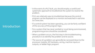
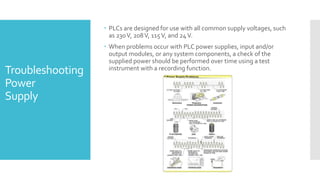
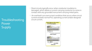
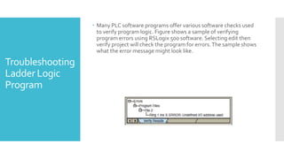
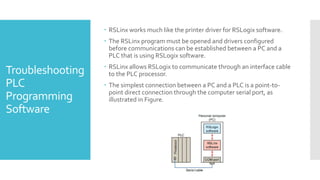
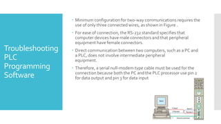
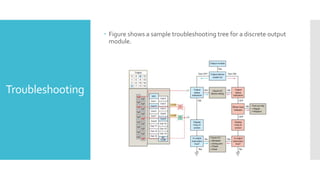
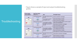
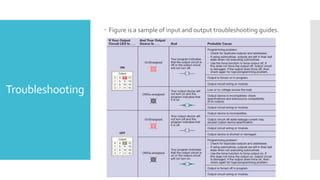
Troubleshooting in PLC
based system
(ProgrammableLogicControllers)
G H Patel College of Engineering andTechnology
Introduction
 In the event of a PLC fault, you should employ a careful and
systematic approach to troubleshoot the system to resolve the
problem.
 PLCs are relatively easy to troubleshoot because the control
program can be displayed on a monitor and watched in real time
as it executes.
 If a control system has been operating, you can be fairly confident
of the accuracy of the program logic.
 For a system that has never worked or is just being commissioned,
programming errors should be considered.
 When a problem occurs, the first step in the troubleshooting
procedure is to identify the problem and its source.
 The source of a problem can generally be narrowed down to the
processor module, I/O hardware, wiring, machine inputs or
outputs, or ladder logic program.
 PLCs are designed for use with all common supply voltages, such
as 230V, 208V, 115V, and 24V.
 When problems occur with PLC power supplies, input and/or
output modules, or any system components, a check of the
supplied power should be performed over time using a test
instrument with a recording function.
Troubleshooting
Power
Supply
 Short circuits typically occur when conductor insulation is
damaged, which allows a current-carrying conductor to come in
contact with any grounded noncurrent-carrying metal parts.
 An overload is an overcurrent condition that occurs when circuit
current exceeds normal PLC operating current and/or designed
circuit current.Troubleshooting
Power
Supply
 Circuit breakers perform the same function as fuses and are
basically tested the same way.
Troubleshooting
Power
Supply
Troubleshooting
Processor
Module
 The processor is responsible for the self-detection of potential
problems.
 It performs error checks during its operation and sends status
information to indicators that are normally located on the front of
the processor module.
 You can diagnose processor faults or obtain more detailed
information about the processor by accessing the processor status
through programming software.
 The processor then monitors itself continually for any problems
that might cause the controller to execute the user program
improperly.
 Depending on the controller, a set of fault relay contacts may be
available.
 The fault relay is controlled by the processor and is activated when
one or more specific fault conditions occur.
 The fault relay contacts are used to disable the outputs and signal
a failure.
 Most PLCs incorporate a watchdog timer to monitor the scan
process of the system.
Troubleshooting
Processor
Module
 If the controller is operating in the RUN mode but output devices
do not operate as programmed, the faults could be associated
with any of the following:
1. Input and output wiring between field devices and modules
2. Field device or module power supplies
3. Input sensing devices
4. Output actuators
5. PLC I/O modules
6. PLC processor
 Narrowing down the problem source can usually be accomplished
by comparing the actual status of the suspect I/O with controller
status indicators.
Troubleshooting
Input
Malfunctions
 Usually each input or output device has at least two status
indicators.One of these indicators is on the I/O module; the other
indicator is provided by the programming device monitor.
 The circuit of Figure illustrates how to check for discrete input
malfunctions .
Troubleshooting
Input
Malfunctions
 Figure shows a typical input device troubleshooting guide.This
guide reviews condition instructions and how their true/false
status relates to external input devices.
Troubleshooting
Input
Malfunctions
Troubleshooting
Output
Malfunctions
 If the blown fuse indicator is not illuminated (fuse OK), then check
to see if the output device is responding to the LED status
indicator.
 An output module’s logic status indicator functions similarly to an
input module’s status indicator.
 When it is on, the status LED indicates that the module’s logic
circuitry has recognized a command from the processor to turn
on.
 If an output rung is energized, the module status indicator is on,
and the output device is not responding, then the wiring to the
output device or the output device itself should be suspected.
Troubleshooting
Output
Malfunctions
Troubleshooting
Ladder Logic
Program
 Many PLC software programs offer various software checks used
to verify program logic. Figure shows a sample of verifying
program errors using RSLogix 500 software. Selecting edit then
verify project will check the program for errors.The sample shows
what the error message might look like.
 The ladder logic program itself is not likely to fail, assuming that
the program was at one time working correctly.
 The ladder logic program itself is not likely to fail, assuming that
the program was at one time working correctly.
 If all other possible sources of trouble have been eliminated, the
ladder logic program should be reloaded into the PLC from the
master copy of the program.
 Make sure the master copy of the program is up to date before
you download it to the PLC.
 Start program troubleshooting by identifying which outputs
operate properly and which outputs do not.
Troubleshooting
Ladder Logic
Program
 You must establish a way for your personal computer (PC)
software to communicate with the programmable logic controller
(PLC) processor.
 Making this connection is known as configuring the
communications.
 The method used to configure the communications varies with
each brand of controller.
 InAllen-Bradley controllers, RSLogix software is required to
develop and edit ladder programs.
 A second software package, RSLinx, is needed to monitor PLC
activity, download a program from your PC to your PLC, and
upload a program from your PLC into your PC.
 You cannot download multiple projects to the PLC and then run
them when required.
Troubleshooting
PLC
Programming
Software
 The PLC will accept only one program at a time, but the program
can consist of multiple subroutine files which can be conditionally
called from the main program RSLinx software is available in
multiple packages to meet the demand for a variety of cost and
functionality requirements.
 This software package is used as the driver between your PC and
PLC processor.
 A driver is a computer program that controls a device.
 For example, you must have the correct printer driver installed in
your PCin order to be able to print a word-processing document
created on your PC. RSLinx works much like the printer driver for
RSLogix software.The RSLinx program must be opened and
drivers configured before communications can be established
between a PC and a PLC that is using.
Troubleshooting
PLC
Programming
Software
 RSLinx works much like the printer driver for RSLogix software.
 The RSLinx program must be opened and drivers configured
before communications can be established between a PC and a
PLC that is using RSLogix software.
 RSLinx allows RSLogix to communicate through an interface cable
to the PLC processor.
 The simplest connection between a PC and a PLC is a point-to-
point direct connection through the computer serial port, as
illustrated in Figure.
Troubleshooting
PLC
Programming
Software
 Minimum configuration for two-way communications requires the
use of only three connected wires, as shown in Figure .
 For ease of connection, the RS-232 standard specifies that
computer devices have male connectors and that peripheral
equipment have female connectors.
 Direct communication between two computers, such as a PC and
a PLC, does not involve intermediate peripheral
equipment.
 Therefore, a serial null-modem type cable must be used for the
connection because both the PC and the PLC processor use pin 2
for data output and pin 3 for data input
Troubleshooting
PLC
Programming
Software
 Some of your troubleshooting can be accomplished by
interpreting the status indicators on the I/O modules.
 The key is to know whether the status indicators are telling you
that there is a fault or that the system is normal.
 Often PLC manufacturers supply a troubleshooting guide, map, or
tree that presents a list of observed problems and their possible
sources.
Troubleshooting
 Figure shows a sample troubleshooting tree for a discrete output
module.
Troubleshooting
 Figure shows a sample of input and output troubleshooting
guides.
Troubleshooting
 Figure is a sample of input and output troubleshooting guides.
Troubleshooting
END ThankYou!!

Troubleshooting in plc

  • 1.
    Troubleshooting in PLC basedsystem (ProgrammableLogicControllers) G H Patel College of Engineering andTechnology
  • 2.
    Introduction  In theevent of a PLC fault, you should employ a careful and systematic approach to troubleshoot the system to resolve the problem.  PLCs are relatively easy to troubleshoot because the control program can be displayed on a monitor and watched in real time as it executes.  If a control system has been operating, you can be fairly confident of the accuracy of the program logic.  For a system that has never worked or is just being commissioned, programming errors should be considered.  When a problem occurs, the first step in the troubleshooting procedure is to identify the problem and its source.  The source of a problem can generally be narrowed down to the processor module, I/O hardware, wiring, machine inputs or outputs, or ladder logic program.
  • 3.
     PLCs aredesigned for use with all common supply voltages, such as 230V, 208V, 115V, and 24V.  When problems occur with PLC power supplies, input and/or output modules, or any system components, a check of the supplied power should be performed over time using a test instrument with a recording function. Troubleshooting Power Supply
  • 4.
     Short circuitstypically occur when conductor insulation is damaged, which allows a current-carrying conductor to come in contact with any grounded noncurrent-carrying metal parts.  An overload is an overcurrent condition that occurs when circuit current exceeds normal PLC operating current and/or designed circuit current.Troubleshooting Power Supply
  • 5.
     Circuit breakersperform the same function as fuses and are basically tested the same way. Troubleshooting Power Supply
  • 6.
    Troubleshooting Processor Module  The processoris responsible for the self-detection of potential problems.  It performs error checks during its operation and sends status information to indicators that are normally located on the front of the processor module.  You can diagnose processor faults or obtain more detailed information about the processor by accessing the processor status through programming software.
  • 7.
     The processorthen monitors itself continually for any problems that might cause the controller to execute the user program improperly.  Depending on the controller, a set of fault relay contacts may be available.  The fault relay is controlled by the processor and is activated when one or more specific fault conditions occur.  The fault relay contacts are used to disable the outputs and signal a failure.  Most PLCs incorporate a watchdog timer to monitor the scan process of the system. Troubleshooting Processor Module
  • 8.
     If thecontroller is operating in the RUN mode but output devices do not operate as programmed, the faults could be associated with any of the following: 1. Input and output wiring between field devices and modules 2. Field device or module power supplies 3. Input sensing devices 4. Output actuators 5. PLC I/O modules 6. PLC processor  Narrowing down the problem source can usually be accomplished by comparing the actual status of the suspect I/O with controller status indicators. Troubleshooting Input Malfunctions
  • 9.
     Usually eachinput or output device has at least two status indicators.One of these indicators is on the I/O module; the other indicator is provided by the programming device monitor.  The circuit of Figure illustrates how to check for discrete input malfunctions . Troubleshooting Input Malfunctions
  • 10.
     Figure showsa typical input device troubleshooting guide.This guide reviews condition instructions and how their true/false status relates to external input devices. Troubleshooting Input Malfunctions
  • 11.
    Troubleshooting Output Malfunctions  If theblown fuse indicator is not illuminated (fuse OK), then check to see if the output device is responding to the LED status indicator.  An output module’s logic status indicator functions similarly to an input module’s status indicator.  When it is on, the status LED indicates that the module’s logic circuitry has recognized a command from the processor to turn on.
  • 12.
     If anoutput rung is energized, the module status indicator is on, and the output device is not responding, then the wiring to the output device or the output device itself should be suspected. Troubleshooting Output Malfunctions
  • 13.
    Troubleshooting Ladder Logic Program  ManyPLC software programs offer various software checks used to verify program logic. Figure shows a sample of verifying program errors using RSLogix 500 software. Selecting edit then verify project will check the program for errors.The sample shows what the error message might look like.
  • 14.
     The ladderlogic program itself is not likely to fail, assuming that the program was at one time working correctly.  The ladder logic program itself is not likely to fail, assuming that the program was at one time working correctly.  If all other possible sources of trouble have been eliminated, the ladder logic program should be reloaded into the PLC from the master copy of the program.  Make sure the master copy of the program is up to date before you download it to the PLC.  Start program troubleshooting by identifying which outputs operate properly and which outputs do not. Troubleshooting Ladder Logic Program
  • 15.
     You mustestablish a way for your personal computer (PC) software to communicate with the programmable logic controller (PLC) processor.  Making this connection is known as configuring the communications.  The method used to configure the communications varies with each brand of controller.  InAllen-Bradley controllers, RSLogix software is required to develop and edit ladder programs.  A second software package, RSLinx, is needed to monitor PLC activity, download a program from your PC to your PLC, and upload a program from your PLC into your PC.  You cannot download multiple projects to the PLC and then run them when required. Troubleshooting PLC Programming Software
  • 16.
     The PLCwill accept only one program at a time, but the program can consist of multiple subroutine files which can be conditionally called from the main program RSLinx software is available in multiple packages to meet the demand for a variety of cost and functionality requirements.  This software package is used as the driver between your PC and PLC processor.  A driver is a computer program that controls a device.  For example, you must have the correct printer driver installed in your PCin order to be able to print a word-processing document created on your PC. RSLinx works much like the printer driver for RSLogix software.The RSLinx program must be opened and drivers configured before communications can be established between a PC and a PLC that is using. Troubleshooting PLC Programming Software
  • 17.
     RSLinx worksmuch like the printer driver for RSLogix software.  The RSLinx program must be opened and drivers configured before communications can be established between a PC and a PLC that is using RSLogix software.  RSLinx allows RSLogix to communicate through an interface cable to the PLC processor.  The simplest connection between a PC and a PLC is a point-to- point direct connection through the computer serial port, as illustrated in Figure. Troubleshooting PLC Programming Software
  • 18.
     Minimum configurationfor two-way communications requires the use of only three connected wires, as shown in Figure .  For ease of connection, the RS-232 standard specifies that computer devices have male connectors and that peripheral equipment have female connectors.  Direct communication between two computers, such as a PC and a PLC, does not involve intermediate peripheral equipment.  Therefore, a serial null-modem type cable must be used for the connection because both the PC and the PLC processor use pin 2 for data output and pin 3 for data input Troubleshooting PLC Programming Software
  • 19.
     Some ofyour troubleshooting can be accomplished by interpreting the status indicators on the I/O modules.  The key is to know whether the status indicators are telling you that there is a fault or that the system is normal.  Often PLC manufacturers supply a troubleshooting guide, map, or tree that presents a list of observed problems and their possible sources. Troubleshooting
  • 20.
     Figure showsa sample troubleshooting tree for a discrete output module. Troubleshooting
  • 21.
     Figure showsa sample of input and output troubleshooting guides. Troubleshooting
  • 22.
     Figure isa sample of input and output troubleshooting guides. Troubleshooting
  • 23.