Downloaded 4,291 times
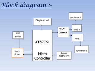


This document describes a student project to create a remote home appliance control system using a microcontroller, GSM modem, and SMS messages. The system allows users to control devices like lights and fans from anywhere via a mobile phone. It aims to provide a low-cost alternative to existing wireless home automation technologies. The document outlines the project objectives, hardware components, software, applications, advantages, and conclusions.