SlideShare a Scribd company logo
AUTOMATIC STREET LIGHT BASED ON
VEHICLE
A Mini Project Submitted in Partial Fulfillment of the Requirement for the Award of the
BACHELOR OF TECHNOLOGY
ELECTRICAL ENGINEERING
AKASH VISHWAKARMA (Roll No.215507)
ANUP SHARMA (Roll No. 215515)
VIJAY PRATAP (Roll No. 215519)
Department of Electrical
Umanath Singh Institute of Engineering & Technology
VEER BAHADUR SINGH PURVANCHAL UNIVERSITY
JAUNPUR, UTTAR PRADESH
1
IC STREET LIGHT BASED ON
VEHICLES MOVEMENT
Project Submitted in Partial Fulfillment of the Requirement for the Award of the
Degree of
BACHELOR OF TECHNOLOGY
in
ELECTRICAL ENGINEERING
Submitted By
AKASH VISHWAKARMA (Roll No.215507)
ANUP SHARMA (Roll No. 215515)
VIJAY PRATAP (Roll No. 215519)
Under the Guidance of
Mr. ANURAG SINGH
Department of Electrical Engineering
Singh Institute of Engineering & Technology
VEER BAHADUR SINGH PURVANCHAL UNIVERSITY
JAUNPUR, UTTAR PRADESH
[2015-2019]
IC STREET LIGHT BASED ON
Project Submitted in Partial Fulfillment of the Requirement for the Award of the
Singh Institute of Engineering & Technology
VEER BAHADUR SINGH PURVANCHAL UNIVERSITY
This is to certify that the project report entitled “
Based on Vehicles Movement
“Umanath Singh Institute of Engineering & Technology
Purvanchal University, Jaunpur
the requirements for the award of the Degree of
formed the basis for the award previously of any degree, diploma, associate ship,
fellowship or any other similar title
Dr. Rajnish Bhaskar Mr. Anurag Singh
(HEAD) (Supervisor)
UNSIET,VBSPU, Jaunpur
Date:-
Place:-
2
CERTIFICATE
This is to certify that the project report entitled “Automatic Street Light
Based on Vehicles Movement” is the bona fide work carried out by students of
Umanath Singh Institute of Engineering & Technology Veer Bahadur Singh
hal University, Jaunpur” during the year 2018 in partial fulfillment of
the requirements for the award of the Degree of B. Tech. The report has not
formed the basis for the award previously of any degree, diploma, associate ship,
fellowship or any other similar title
Dr. Rajnish Bhaskar Mr. Anurag Singh
(HEAD) (Supervisor)
UNSIET,VBSPU, Jaunpur
Automatic Street Light
fide work carried out by students of
Veer Bahadur Singh
in partial fulfillment of
. The report has not
formed the basis for the award previously of any degree, diploma, associate ship,
Dr. Rajnish Bhaskar Mr. Anurag Singh
(HEAD) (Supervisor)
3
DECLARATION
I hereby declare that the project report entitled “Automatic Street Light
Based on Vehicles Movement” submitted is our original work and the report has
not formed the basis for the award of any degree, associate ship, fellowship or any
other similar title.
Date:
Place:
AKASH VISHWAKARMA (215507)
ANUP SHARMA (215515)
VIJAY PRATAP (215519)
4
ACKNOWLEDGEMENT
It gives me great pleasure to express my gratitude and heart full thanks to
all those who are helping me in complete this project.
I want to thank to “Mr. ANURAG SINGH”, who has always encouraged
and help me in making this project. In addition to this, I am grateful to other
faculties too who made me in right direction and gave me their precious time and
expert guidance whenever necessary through which I could achieve this extent.
At last but not the least I am feeling glad to say about my family whose
wishes are always with me, without which it was not possible for me to reach this
extent.
I hope my work is praised and my efforts render fruitful result.
THANK YOU
Date:-
Place:-
Akash Vishwakarma (215507)
Anup Sharma (215515)
Vijay Pratap (215519)
5
ABSTRACT
In this study, Generally, street light controlling system is a simple concept
which uses a transistor to turn ON in the night time and turn OFF during the day
time. The entire process can be done by a using a sensor namely IR (Infra Red).
Nowadays conserving the energy is an essential part and day by day energy
resources are getting decreased. So our next generations may may face a lot of
problems due to this lack of resources. This system doesn’t need a manual
operation to turn ON/OFF the street lights. The street light system detects whether
there is need of light or not.
Keywords: IR sensor, Amplifier-LM358 ,LED.
6
TABLE OF CONTENTS
CONTENT ……………………………………………………………...PAGE NO.
Declaration……………………………………………………………………………………………….…iii
Acknowledgement…………………………………………………………………………………………..iv
Abstract ………………………………………………………………………………………………………v
Table of Contents …………………………………………………………………………………………..vi
Automatic Street Light Based on Vehicles Movement
Introduction .........................................................................................................................7
Objective..............................................................................................................................7
1.Block diagram...................................................................................................................8
2.Working ............................................................................................................................9
3.Hardware used ..................................................................................................................9
3.1IR Sensor.......................................................................................................................10
3.11IR Sensor Circuit Diagram and Working Principle ........................................................... 10
3.12Principles of Operation....................................................................................................... 12
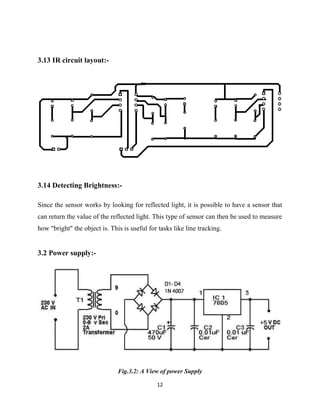
3.13Detecting Brightness .......................................................................................................... 12
3.2Power supply.................................................................................................................13
3.21Working.............................................................................................................................. 14
3.22Linear power supply........................................................................................................... 15
3.23Switched-mode power supply............................................................................................ 13
3.24Electrical Transformer........................................................................................................ 15
3.25The Basic Working Principle............................................................................................. 16
4.Applications and Advantages .........................................................................................18
5.Disadvantages .................................................................................................................18
6.Future Development: ......................................................................................................18
References .........................................................................................................................19
7
AUTOMATIC STREET LIGHT BASED ON
VEHICLES MOVEMENT
INTRODUCTION
The idea of designing a new system for the road light that do
not consume huge amount of electricity and illuminate large areas with the highest
intensity of light is concerning each engineer working in this field. Providing road
lighting is one of the most important and expensive responsibilities. Lighting can account
for 10–38% of the total energy bill in typical worldwide. Road lighting is a particularly
critical concern for public authorities in developing countries because of its strategic
importance for economic and social stability. Inefficient lighting wastes significant
financial resources every year, and poor lighting creates unsafe conditions. Energy
efficient technologies and design mechanism can reduce cost of the street lighting
drastically.
Manual control is prone to errors and leads to energy wastages and manually
dimming during mid night is impracticable. Also, dynamically tracking the light level is
manually impracticable. The current trend is the introduction of automation and remote
management solutions to control lighting .
Objective:-
The objective of the system is to design and develop automatic road light using IR
sensor.
1.Block diagram:-
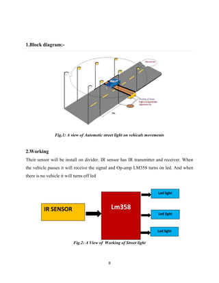
Fig.1: A view of Autometic street light on vehicals movements
2.Working
Their sensor will be install on divider
the vehicle passes it will receive the signal and Op
there is no vehicle it will turns off led
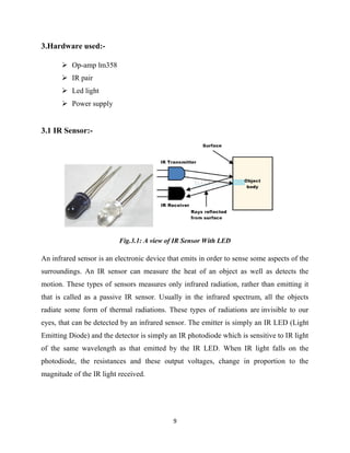
Fig.2:
IR SENSOR
8
A view of Autometic street light on vehicals movements
nsor will be install on divider. IR sensor has IR transmitter and receiver. When
eive the signal and Op-amp LM358 turns on led. And when
icle it will turns off led
Fig.2: A View of Working of Street light
Lm358
Led light
Led light
Led light
A view of Autometic street light on vehicals movements
IR sensor has IR transmitter and receiver. When
358 turns on led. And when
Led light
Led light
Led light
9
3.Hardware used:-
 Op-amp lm358
 IR pair
 Led light
 Power supply
3.1 IR Sensor:-
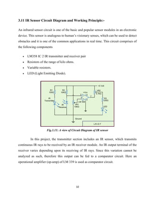
Fig.3.1: A view of IR Sensor With LED
An infrared sensor is an electronic device that emits in order to sense some aspects of the
surroundings. An IR sensor can measure the heat of an object as well as detects the
motion. These types of sensors measures only infrared radiation, rather than emitting it
that is called as a passive IR sensor. Usually in the infrared spectrum, all the objects
radiate some form of thermal radiations. These types of radiations are invisible to our
eyes, that can be detected by an infrared sensor. The emitter is simply an IR LED (Light
Emitting Diode) and the detector is simply an IR photodiode which is sensitive to IR light
of the same wavelength as that emitted by the IR LED. When IR light falls on the
photodiode, the resistances and these output voltages, change in proportion to the
magnitude of the IR light received.
10
3.11 IR Sensor Circuit Diagram and Working Principle:-
An infrared sensor circuit is one of the basic and popular sensor modules in an electronic
device. This sensor is analogous to human’s visionary senses, which can be used to detect
obstacles and it is one of the common applications in real time. This circuit comprises of
the following components
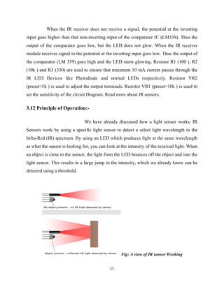
 LM358 IC 2 IR transmitter and receiver pair
 Resistors of the range of kilo ohms.
 Variable resistors.
 LED (Light Emitting Diode).
Fig.3.11: A view of Circuit Diagram of IR sensor
In this project, the transmitter section includes an IR sensor, which transmits
continuous IR rays to be received by an IR receiver module. An IR output terminal of the
receiver varies depending upon its receiving of IR rays. Since this variation cannot be
analyzed as such, therefore this output can be fed to a comparator circuit. Here an
operational amplifier (op-amp) of LM 339 is used as comparator circuit.
11
When the IR receiver does not receive a signal, the potential at the inverting
input goes higher than that non-inverting input of the comparator IC (LM339). Thus the
output of the comparator goes low, but the LED does not glow. When the IR receiver
module receives signal to the potential at the inverting input goes low. Thus the output of
the comparator (LM 339) goes high and the LED starts glowing. Resistor R1 (100 ), R2
(10k ) and R3 (330) are used to ensure that minimum 10 mA current passes through the
IR LED Devices like Photodiode and normal LEDs respectively. Resistor VR2
(preset=5k ) is used to adjust the output terminals. Resistor VR1 (preset=10k ) is used to
set the sensitivity of the circuit Diagram. Read more about IR sensors.
3.12 Principle of Operation:-
We have already discussed how a light sensor works. IR
Sensors work by using a specific light sensor to detect a select light wavelength in the
Infra-Red (IR) spectrum. By using an LED which produces light at the same wavelength
as what the sensor is looking for, you can look at the intensity of the received light. When
an object is close to the sensor, the light from the LED bounces off the object and into the
light sensor. This results in a large jump in the intensity, which we already know can be
detected using a threshold.
Fig: A view of IR sensor Working
12
3.13 IR circuit layout:-
3.14 Detecting Brightness:-
Since the sensor works by looking for reflected light, it is possible to have a sensor that
can return the value of the reflected light. This type of sensor can then be used to measure
how "bright" the object is. This is useful for tasks like line tracking.
3.2 Power supply:-
Fig.3.2: A View of power Supply
13
3.21 Working:-
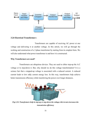
This design is based around 4 main parts. A transformer, bridge rectifier,
a smoothing capacitor and the LM7805 chip which contains a 'linear voltage
regulator'. Transformer is used to convert 220 VAC to 18 VAC. Bridge rectifier is
used to convert AC to ripple DC. Capacitor is used to filter ripples from dc. 7805
voltage regulator is used to regulate voltage to 5 VDC. LED is used for indication
power supply is working or not.
3.22 Linear power supply:-
A linear regulated power supply regulates the output voltage
by dropping excess voltage in a series dissipative component. They use a moderately
complex regulator circuit to achieve very low load and line regulation. Linear regulated
power supplies also have very little ripple and very little output noise. The above power
supply is linear power supply.
3.23 Switched-mode power supply:-
In a switched-mode power supply (SMPS), the
AC mains input is directly rectified and then filtered to obtain a DC voltage. The
resulting DC voltage is then switched on and off at a high frequency by electronic
switching circuitry, thus producing an AC current that will pass through a high-frequency
transformer or inductor. Switching occurs at a very high frequency (typically 10 kHz —
1 MHz), thereby enabling the use of transformers and filter capacitors that are much
smaller, lighter, and less expensive than those found in linear power supplies operating at
mains frequency. After the inductor or transformer secondary, the high frequency AC is
rectified and filtered to produce the DC output voltage. If the SMPS uses an adequately
insulated high-frequency transformer, the output will be electrically isolated from the
mains; this feature is often essential for safety
14
Switched-mode power supplies are usually regulated, and to keep the output
voltage constant, the power supply employs a feedback controller that monitors current
drawn by the load. The switching duty cycle increases as power output requirements
increase.
SMPSs often include safety features such as current limiting or a crowbar
circuit to help protect the device and the user from harm. In the event that an abnormal
high-current power draw is detected, the switched-mode supply can assume this is a
direct short and will shut itself down before damage is done. PC power supplies often
provide a power good signal to the motherboard; the absence of this signal prevents
operation when abnormal supply voltages are present.
Some SMPSs have an absolute limit on their minimum current output. They
are only able to output above a certain power level and cannot function below that point.
In a no-load condition the frequency of the power slicing circuit increases to great speed,
causing the isolated transformer to act as a Tesla coil, causing damage due to the
resulting very high voltage power spikes. Switched-mode supplies with protection
circuits may briefly turn on but then shut down when no load has been detected. A very
small low-power dummy load such as a ceramic power resistor or 10-watt light bulb can
be attached to the supply to allow it to run with no primary load attached.
The switch-mode power supplies used in computers have historically had low
power factors and have also been significant sources of line interference (due to induced
power line harmonics and transients). In simple switch-mode power supplies, the input
stage may distort the line voltage waveform, which can adversely affect other loads (and
result in poor power quality for other utility customers), and cause unnecessary heating in
wires and distribution equipment. Furthermore, customers incur higher electric bills when
operating lower power factor loads. To circumvent these problems, some computer
switch-mode power supplies perform power factor correction, and may employ input
filters or additional switching stages to reduce line interference.
15
3.24 Electrical Transformer:-
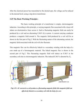
Transformers are capable of receiving AC power at one
voltage and delivering it at another voltage. In this article, we will go through the
working and construction of a 3 phase transformer by starting from its simplest form. We
will also understand what power transformer is and how it is constructed.
Why Transformers are used?
Transformers are ubiquitous devices. They are used to either step-up the A.C
voltage or to step-down it. But, why should we do this voltage transformation? It is a
science fact that a stepped-up voltage is associated with a reduced current. A reduced
current leads to low eddy current energy loss. In this way, transformers help achieve
better transmission efficiency while transferring the power over longer distances.
Fig.3.24: Transformers help in step-up or step-down the voltage; this in turn increases the
transmission efficiency
16
After the electrical power has transmitted to the desired spot, the voltage can be reduced
to the desired level, using a step-down transformer.
3.25 The Basic Working Principle:-
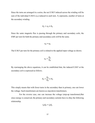
The basic working principle of a transformer is simple, electromagnetic
induction. According to this principle, a varying magnetic flux associated with a loop will
induce an electromotive force across it. Such a fluctuating magnetic field can easily be
produced by a coil and an alternating E.M.F (EP) system. A current carrying conductor
produces a magnetic field around it. The magnetic field produced by a coil will be as
shown in the first part of Fig.2. With the fluctuating nature of the alternating current, the
magnetic field associated with the coil will also fluctuate.
This magnetic flux can be effectively linked to a secondary winding with the help of a
core made up of a ferromagnetic material. The linked magnetic flux is shown in the
second part of Fig.2. This fluctuating magnetic field will induce an E.M.F in the
secondary coils due to electromagnetic induction. The induced E.M.F is denoted by ES.
Fig.3.25: AC current in a coil produces a fluctuating magnetic field; this magnetic field can
effectively linked to a secondary coil with the help of a core
17
Since the turns are arranged in a series, the net E.M.F induced across the winding will be
sum of the individual E.M.Fs (eS) induced in each turn. Ns represents, number of turns at
the secondary winding.
Since the same magnetic flux is passing through the primary and secondary coils, the
EMF per turn for both the primary and secondary coils will be the same.
The E.M.F per turn for the primary coil is related to the applied input voltage as shown.
By rearranging the above equations, it can be established that, the induced E.M.F at the
secondary coil is expressed as follows.
This simply means that with fewer turns in the secondary than in primary, one can lower
the voltage. Such transformers are known as step-down transformers.
For the reverse case, one can increase the voltage (step-up transformer).But
since energy is conserved, the primary and secondary currents have to obey the following
relationship.
18
4. Applications and Advantages:-
1. It can use in street light, road light etc.
2. It reduce electricity bills.
3. It is reliable , safe and easy to develop.
5. Disadvantages:-
1. The system will not update due to network problem.
2. The device is not water resistant keep avoid from moisture.
3. The SMD components of the device are sensitive to EDS.
6. Future Development:
 In future we use microcontroller to make the system more reliable.
19
 References:-
[1] D. A. Devi and A. Kumar, Design and Implementation of CPLD based Solar Power
Saving System for Street Lights and Automatic Traffic Controller, International
Journal of Scientific and Research Publications, Vol. 2, Issue11, November 2012.
[2] J. Mohelnikova, Electric Energy Savings and Light Guides, Energy& Environment,
3rd IASME/WSEAS International Conference on, Cambridge, UK, February 2008,
pp.470-474.
[3] M. A. Wazed, N. Nafis, M. T. Islam and A. SSayem, Design and Fabrication of
Automatic Street Light Control System, Engineering e-Transaction, Vol. 5, No. 1,
June 2010, pp 27-34
[4] R. Priyasree, R. Kauser, E. Vinitha and N. Gangatharan, Automatic Street Light
Intensity Control and Road Safety Module Using Embedded System, International
Conference on Computing and Control Engineering, April 2012.
[5] K. S. SudhakaS. Bhaskar, Automatic Street Light Control System, International
Journal of Emerging Technology and Advanced Engineering, Vol. 3, May 2013, PP.
188-189.
[6] K.Y. Rajput, G. Khatav, M. Pujari, P. Yadav, Intelligent Street Lighting System
Using Gsm, International Journal of Engineering Science Invention, Vol2, Issue 3,
March 2013, PP. 60-69.
[7] M. Popa, C. Cepişcă, Energy Consumption
Saving Solutions Based on Intelligent Street Lighting Control System. U.P.B. Sci.
Bull., Vol. 73, April 2011, PP. 297-308.
[8] R. Mohamaddoust, A. T. Haghighat, M. J. M. Sharif and N. Capanni, A Novel
Design of an Automatic Lighting Control System for a Wireless Sensor Network
with Increased Sensor Lifetime and Reduced Sensor Numbers, Sensors, Vol. 11, PP.
8933-8952.
20

More Related Content

What's hot

Mini-Project-1 Report
Mini-Project-1 ReportMini-Project-1 Report
Mini-Project-1 ReportVASAV SHETHNA
 
Solar tracking system
Solar tracking systemSolar tracking system
Solar tracking system
Reejasunil
 
Final report of line follower robot
Final report of line follower robotFinal report of line follower robot
Final report of line follower robot
Rohit Dadoriya
 
Automatic street light control using ldr PPT
Automatic street light control using ldr PPTAutomatic street light control using ldr PPT
Automatic street light control using ldr PPT
SABIR ALI MOLLAH
 
Automatic control of street light using LDR
Automatic control of street light using LDRAutomatic control of street light using LDR
Automatic control of street light using LDR
Devang Loharikar
 
Smart street light system
Smart street light systemSmart street light system
Smart street light system
Kuriakose Mathew
 
AUTOMATIC BOTTLE FILLING
AUTOMATIC BOTTLE FILLING AUTOMATIC BOTTLE FILLING
AUTOMATIC BOTTLE FILLING
rehaan ukaye
 
Railway Accident Avoiding System: A Safety Measure
Railway Accident Avoiding System: A Safety MeasureRailway Accident Avoiding System: A Safety Measure
Railway Accident Avoiding System: A Safety Measure
Yantralive Parts Technology Pvt. Ltd
 
Movement Sensed Automatic Door Opening System
Movement Sensed Automatic Door Opening SystemMovement Sensed Automatic Door Opening System
Movement Sensed Automatic Door Opening System
Edgefxkits & Solutions
 
Li-Fi Audio Transmission Project Documentation/Report
Li-Fi Audio Transmission Project Documentation/ReportLi-Fi Audio Transmission Project Documentation/Report
Li-Fi Audio Transmission Project Documentation/Report
TSriyaSharma
 
Smart street lighting control system project PPT
Smart street lighting control system project PPT Smart street lighting control system project PPT
Smart street lighting control system project PPT
PetchiMuthu26
 
PLC Based Automatic car wash system By Irfan Anjum
PLC Based Automatic car wash system By Irfan AnjumPLC Based Automatic car wash system By Irfan Anjum
PLC Based Automatic car wash system By Irfan Anjum
Isra University Islamabad
 
Internship Report on IOT & Robotics
Internship Report on IOT & RoboticsInternship Report on IOT & Robotics
Internship Report on IOT & Robotics
Aman Jaiswal
 
automatic railway gate control system using arduino
automatic railway gate control system using arduinoautomatic railway gate control system using arduino
automatic railway gate control system using arduino
antivirusspam
 
PROJECT REPORT ON Home automation using by Bluetooth
 PROJECT REPORT ON Home automation using by Bluetooth PROJECT REPORT ON Home automation using by Bluetooth
PROJECT REPORT ON Home automation using by Bluetooth
Aakashkumar276
 
Solar cell tracking system
Solar cell tracking systemSolar cell tracking system
Solar cell tracking system
moazalhosne
 
Automatic railway gate control using arduino uno
Automatic railway gate control using arduino unoAutomatic railway gate control using arduino uno
Automatic railway gate control using arduino uno
selvalakshmi24
 
Automatic street light
Automatic street lightAutomatic street light
Automatic street light
Anu Antony
 
Automatic street light control using LDR.
Automatic street light control using LDR.Automatic street light control using LDR.
Automatic street light control using LDR.
Fazlur Rahman
 

What's hot (20)

Mini-Project-1 Report
Mini-Project-1 ReportMini-Project-1 Report
Mini-Project-1 Report
 
Solar tracker ppt
Solar tracker pptSolar tracker ppt
Solar tracker ppt
 
Solar tracking system
Solar tracking systemSolar tracking system
Solar tracking system
 
Final report of line follower robot
Final report of line follower robotFinal report of line follower robot
Final report of line follower robot
 
Automatic street light control using ldr PPT
Automatic street light control using ldr PPTAutomatic street light control using ldr PPT
Automatic street light control using ldr PPT
 
Automatic control of street light using LDR
Automatic control of street light using LDRAutomatic control of street light using LDR
Automatic control of street light using LDR
 
Smart street light system
Smart street light systemSmart street light system
Smart street light system
 
AUTOMATIC BOTTLE FILLING
AUTOMATIC BOTTLE FILLING AUTOMATIC BOTTLE FILLING
AUTOMATIC BOTTLE FILLING
 
Railway Accident Avoiding System: A Safety Measure
Railway Accident Avoiding System: A Safety MeasureRailway Accident Avoiding System: A Safety Measure
Railway Accident Avoiding System: A Safety Measure
 
Movement Sensed Automatic Door Opening System
Movement Sensed Automatic Door Opening SystemMovement Sensed Automatic Door Opening System
Movement Sensed Automatic Door Opening System
 
Li-Fi Audio Transmission Project Documentation/Report
Li-Fi Audio Transmission Project Documentation/ReportLi-Fi Audio Transmission Project Documentation/Report
Li-Fi Audio Transmission Project Documentation/Report
 
Smart street lighting control system project PPT
Smart street lighting control system project PPT Smart street lighting control system project PPT
Smart street lighting control system project PPT
 
PLC Based Automatic car wash system By Irfan Anjum
PLC Based Automatic car wash system By Irfan AnjumPLC Based Automatic car wash system By Irfan Anjum
PLC Based Automatic car wash system By Irfan Anjum
 
Internship Report on IOT & Robotics
Internship Report on IOT & RoboticsInternship Report on IOT & Robotics
Internship Report on IOT & Robotics
 
automatic railway gate control system using arduino
automatic railway gate control system using arduinoautomatic railway gate control system using arduino
automatic railway gate control system using arduino
 
PROJECT REPORT ON Home automation using by Bluetooth
 PROJECT REPORT ON Home automation using by Bluetooth PROJECT REPORT ON Home automation using by Bluetooth
PROJECT REPORT ON Home automation using by Bluetooth
 
Solar cell tracking system
Solar cell tracking systemSolar cell tracking system
Solar cell tracking system
 
Automatic railway gate control using arduino uno
Automatic railway gate control using arduino unoAutomatic railway gate control using arduino uno
Automatic railway gate control using arduino uno
 
Automatic street light
Automatic street lightAutomatic street light
Automatic street light
 
Automatic street light control using LDR.
Automatic street light control using LDR.Automatic street light control using LDR.
Automatic street light control using LDR.
 

Similar to Automatic street light based on vehicles movement report

Smart street light using microcontroller
Smart street light using microcontrollerSmart street light using microcontroller
Smart street light using microcontroller
bshetty2000
 
Project (2)
Project (2)Project (2)
Project (2)
KarthiKeyani10
 
GR17.pdf
GR17.pdfGR17.pdf
GR17.pdf
Gniseries
 
IRJET - Smart Street Light based on Arduino
IRJET -  	  Smart Street Light based on ArduinoIRJET -  	  Smart Street Light based on Arduino
IRJET - Smart Street Light based on Arduino
IRJET Journal
 
automatic street light control using aurdino,PIR,LDR tinker cad circuit
automatic street light control using aurdino,PIR,LDR tinker cad circuitautomatic street light control using aurdino,PIR,LDR tinker cad circuit
automatic street light control using aurdino,PIR,LDR tinker cad circuit
anujabarge3
 
IRJET - Automatic Street Light Controller
IRJET -  	  Automatic Street Light ControllerIRJET -  	  Automatic Street Light Controller
IRJET - Automatic Street Light Controller
IRJET Journal
 
IRJET- Smart Street Light Control System
IRJET- Smart Street Light Control SystemIRJET- Smart Street Light Control System
IRJET- Smart Street Light Control System
IRJET Journal
 
IRJET- Brainy Streets with Automatic Lighting System
IRJET-  	  Brainy Streets with Automatic Lighting SystemIRJET-  	  Brainy Streets with Automatic Lighting System
IRJET- Brainy Streets with Automatic Lighting System
IRJET Journal
 
Arduino Based Project- Smart Street Light System
Arduino Based Project- Smart Street Light SystemArduino Based Project- Smart Street Light System
Arduino Based Project- Smart Street Light System
RushikeshChoudhery
 
Kg
KgKg
SMART STREET LIGHTING SYSTEM BASED ON SENSORS USING PLC AND SCADA
SMART STREET LIGHTING SYSTEM BASED ON SENSORS USING PLC AND SCADASMART STREET LIGHTING SYSTEM BASED ON SENSORS USING PLC AND SCADA
SMART STREET LIGHTING SYSTEM BASED ON SENSORS USING PLC AND SCADA
IAEME Publication
 
IRJET - Real Time Street Light using Raspberry Pi
IRJET - Real Time Street Light using Raspberry PiIRJET - Real Time Street Light using Raspberry Pi
IRJET - Real Time Street Light using Raspberry Pi
IRJET Journal
 
SMART STREET LIGHTING Using IOT
SMART STREET LIGHTING Using IOTSMART STREET LIGHTING Using IOT
SMART STREET LIGHTING Using IOT
IRJET Journal
 
I010234548
I010234548I010234548
I010234548
IOSR Journals
 
Smart street light detector
Smart street light detectorSmart street light detector
Smart street light detector
siddharth bhatt
 
Smart street lighting system based on sensors using plc and scada
Smart street lighting system based on sensors using plc and scadaSmart street lighting system based on sensors using plc and scada
Smart street lighting system based on sensors using plc and scada
IAEME Publication
 
Automatic control system of highway lights
Automatic control system of highway lightsAutomatic control system of highway lights
Automatic control system of highway lights
TELKOMNIKA JOURNAL
 
IRJET - Vehicle Movement based Street Lights
IRJET - Vehicle Movement based Street LightsIRJET - Vehicle Movement based Street Lights
IRJET - Vehicle Movement based Street Lights
IRJET Journal
 
IRJET- Automatic Highway Lighting System
IRJET- Automatic Highway Lighting SystemIRJET- Automatic Highway Lighting System
IRJET- Automatic Highway Lighting System
IRJET Journal
 
Design and Implementation of Automatic Street Light Control Using Sensors and...
Design and Implementation of Automatic Street Light Control Using Sensors and...Design and Implementation of Automatic Street Light Control Using Sensors and...
Design and Implementation of Automatic Street Light Control Using Sensors and...
IJERA Editor
 

Similar to Automatic street light based on vehicles movement report (20)

Smart street light using microcontroller
Smart street light using microcontrollerSmart street light using microcontroller
Smart street light using microcontroller
 
Project (2)
Project (2)Project (2)
Project (2)
 
GR17.pdf
GR17.pdfGR17.pdf
GR17.pdf
 
IRJET - Smart Street Light based on Arduino
IRJET -  	  Smart Street Light based on ArduinoIRJET -  	  Smart Street Light based on Arduino
IRJET - Smart Street Light based on Arduino
 
automatic street light control using aurdino,PIR,LDR tinker cad circuit
automatic street light control using aurdino,PIR,LDR tinker cad circuitautomatic street light control using aurdino,PIR,LDR tinker cad circuit
automatic street light control using aurdino,PIR,LDR tinker cad circuit
 
IRJET - Automatic Street Light Controller
IRJET -  	  Automatic Street Light ControllerIRJET -  	  Automatic Street Light Controller
IRJET - Automatic Street Light Controller
 
IRJET- Smart Street Light Control System
IRJET- Smart Street Light Control SystemIRJET- Smart Street Light Control System
IRJET- Smart Street Light Control System
 
IRJET- Brainy Streets with Automatic Lighting System
IRJET-  	  Brainy Streets with Automatic Lighting SystemIRJET-  	  Brainy Streets with Automatic Lighting System
IRJET- Brainy Streets with Automatic Lighting System
 
Arduino Based Project- Smart Street Light System
Arduino Based Project- Smart Street Light SystemArduino Based Project- Smart Street Light System
Arduino Based Project- Smart Street Light System
 
Kg
KgKg
Kg
 
SMART STREET LIGHTING SYSTEM BASED ON SENSORS USING PLC AND SCADA
SMART STREET LIGHTING SYSTEM BASED ON SENSORS USING PLC AND SCADASMART STREET LIGHTING SYSTEM BASED ON SENSORS USING PLC AND SCADA
SMART STREET LIGHTING SYSTEM BASED ON SENSORS USING PLC AND SCADA
 
IRJET - Real Time Street Light using Raspberry Pi
IRJET - Real Time Street Light using Raspberry PiIRJET - Real Time Street Light using Raspberry Pi
IRJET - Real Time Street Light using Raspberry Pi
 
SMART STREET LIGHTING Using IOT
SMART STREET LIGHTING Using IOTSMART STREET LIGHTING Using IOT
SMART STREET LIGHTING Using IOT
 
I010234548
I010234548I010234548
I010234548
 
Smart street light detector
Smart street light detectorSmart street light detector
Smart street light detector
 
Smart street lighting system based on sensors using plc and scada
Smart street lighting system based on sensors using plc and scadaSmart street lighting system based on sensors using plc and scada
Smart street lighting system based on sensors using plc and scada
 
Automatic control system of highway lights
Automatic control system of highway lightsAutomatic control system of highway lights
Automatic control system of highway lights
 
IRJET - Vehicle Movement based Street Lights
IRJET - Vehicle Movement based Street LightsIRJET - Vehicle Movement based Street Lights
IRJET - Vehicle Movement based Street Lights
 
IRJET- Automatic Highway Lighting System
IRJET- Automatic Highway Lighting SystemIRJET- Automatic Highway Lighting System
IRJET- Automatic Highway Lighting System
 
Design and Implementation of Automatic Street Light Control Using Sensors and...
Design and Implementation of Automatic Street Light Control Using Sensors and...Design and Implementation of Automatic Street Light Control Using Sensors and...
Design and Implementation of Automatic Street Light Control Using Sensors and...
 

More from Indian Institute of Technology Guwahati

Operation and Control of Inductive Wireless Power Transfer
Operation and Control of Inductive Wireless Power Transfer Operation and Control of Inductive Wireless Power Transfer
Operation and Control of Inductive Wireless Power Transfer
Indian Institute of Technology Guwahati
 
CUK CONVERTER.pdf
CUK CONVERTER.pdfCUK CONVERTER.pdf
Three_Phase_Inverter_in_120_mode.pdf
Three_Phase_Inverter_in_120_mode.pdfThree_Phase_Inverter_in_120_mode.pdf
Three_Phase_Inverter_in_120_mode.pdf
Indian Institute of Technology Guwahati
 
Flyback Converter.pdf
Flyback Converter.pdfFlyback Converter.pdf
Buck converter.pdf
Buck converter.pdfBuck converter.pdf
Boost Converter simulation model.pdf
Boost Converter simulation model.pdfBoost Converter simulation model.pdf
Boost Converter simulation model.pdf
Indian Institute of Technology Guwahati
 
Buck Boost Converter with simulation model.pdf
Buck Boost Converter with simulation model.pdfBuck Boost Converter with simulation model.pdf
Buck Boost Converter with simulation model.pdf
Indian Institute of Technology Guwahati
 
TUNING OF DC MOTOR BY USING PSO & PID
TUNING OF DC MOTOR BY USING PSO & PIDTUNING OF DC MOTOR BY USING PSO & PID
TUNING OF DC MOTOR BY USING PSO & PID
Indian Institute of Technology Guwahati
 
ZERO TURNING RADIUS STRETCHER (ZTRS)
ZERO TURNING RADIUS STRETCHER (ZTRS)ZERO TURNING RADIUS STRETCHER (ZTRS)
ZERO TURNING RADIUS STRETCHER (ZTRS)
Indian Institute of Technology Guwahati
 
DLW Electrical Engineering industrial training Report
DLW Electrical Engineering industrial training Report DLW Electrical Engineering industrial training Report
DLW Electrical Engineering industrial training Report
Indian Institute of Technology Guwahati
 
UPQC ppt main
UPQC ppt mainUPQC ppt main
Power quality improvement using UPQC
Power quality improvement using UPQCPower quality improvement using UPQC
Power quality improvement using UPQC
Indian Institute of Technology Guwahati
 
Automatic road light based on vehicles movement
Automatic road light based on vehicles movementAutomatic road light based on vehicles movement
Automatic road light based on vehicles movement
Indian Institute of Technology Guwahati
 
An overview of FACTS devices
An overview of FACTS devicesAn overview of FACTS devices
An overview of FACTS devices
Indian Institute of Technology Guwahati
 
DLW Electrical Engineering industrial training slides
DLW Electrical Engineering industrial training slidesDLW Electrical Engineering industrial training slides
DLW Electrical Engineering industrial training slides
Indian Institute of Technology Guwahati
 

More from Indian Institute of Technology Guwahati (15)

Operation and Control of Inductive Wireless Power Transfer
Operation and Control of Inductive Wireless Power Transfer Operation and Control of Inductive Wireless Power Transfer
Operation and Control of Inductive Wireless Power Transfer
 
CUK CONVERTER.pdf
CUK CONVERTER.pdfCUK CONVERTER.pdf
CUK CONVERTER.pdf
 
Three_Phase_Inverter_in_120_mode.pdf
Three_Phase_Inverter_in_120_mode.pdfThree_Phase_Inverter_in_120_mode.pdf
Three_Phase_Inverter_in_120_mode.pdf
 
Flyback Converter.pdf
Flyback Converter.pdfFlyback Converter.pdf
Flyback Converter.pdf
 
Buck converter.pdf
Buck converter.pdfBuck converter.pdf
Buck converter.pdf
 
Boost Converter simulation model.pdf
Boost Converter simulation model.pdfBoost Converter simulation model.pdf
Boost Converter simulation model.pdf
 
Buck Boost Converter with simulation model.pdf
Buck Boost Converter with simulation model.pdfBuck Boost Converter with simulation model.pdf
Buck Boost Converter with simulation model.pdf
 
TUNING OF DC MOTOR BY USING PSO & PID
TUNING OF DC MOTOR BY USING PSO & PIDTUNING OF DC MOTOR BY USING PSO & PID
TUNING OF DC MOTOR BY USING PSO & PID
 
ZERO TURNING RADIUS STRETCHER (ZTRS)
ZERO TURNING RADIUS STRETCHER (ZTRS)ZERO TURNING RADIUS STRETCHER (ZTRS)
ZERO TURNING RADIUS STRETCHER (ZTRS)
 
DLW Electrical Engineering industrial training Report
DLW Electrical Engineering industrial training Report DLW Electrical Engineering industrial training Report
DLW Electrical Engineering industrial training Report
 
UPQC ppt main
UPQC ppt mainUPQC ppt main
UPQC ppt main
 
Power quality improvement using UPQC
Power quality improvement using UPQCPower quality improvement using UPQC
Power quality improvement using UPQC
 
Automatic road light based on vehicles movement
Automatic road light based on vehicles movementAutomatic road light based on vehicles movement
Automatic road light based on vehicles movement
 
An overview of FACTS devices
An overview of FACTS devicesAn overview of FACTS devices
An overview of FACTS devices
 
DLW Electrical Engineering industrial training slides
DLW Electrical Engineering industrial training slidesDLW Electrical Engineering industrial training slides
DLW Electrical Engineering industrial training slides
 

Recently uploaded

Fundamentals of Electric Drives and its applications.pptx
Fundamentals of Electric Drives and its applications.pptxFundamentals of Electric Drives and its applications.pptx
Fundamentals of Electric Drives and its applications.pptx
manasideore6
 
Industrial Training at Shahjalal Fertilizer Company Limited (SFCL)
Industrial Training at Shahjalal Fertilizer Company Limited (SFCL)Industrial Training at Shahjalal Fertilizer Company Limited (SFCL)
Industrial Training at Shahjalal Fertilizer Company Limited (SFCL)
MdTanvirMahtab2
 
Design and Analysis of Algorithms-DP,Backtracking,Graphs,B&B
Design and Analysis of Algorithms-DP,Backtracking,Graphs,B&BDesign and Analysis of Algorithms-DP,Backtracking,Graphs,B&B
Design and Analysis of Algorithms-DP,Backtracking,Graphs,B&B
Sreedhar Chowdam
 
ML for identifying fraud using open blockchain data.pptx
ML for identifying fraud using open blockchain data.pptxML for identifying fraud using open blockchain data.pptx
ML for identifying fraud using open blockchain data.pptx
Vijay Dialani, PhD
 
Immunizing Image Classifiers Against Localized Adversary Attacks
Immunizing Image Classifiers Against Localized Adversary AttacksImmunizing Image Classifiers Against Localized Adversary Attacks
Immunizing Image Classifiers Against Localized Adversary Attacks
gerogepatton
 
14 Template Contractual Notice - EOT Application
14 Template Contractual Notice - EOT Application14 Template Contractual Notice - EOT Application
14 Template Contractual Notice - EOT Application
SyedAbiiAzazi1
 
Final project report on grocery store management system..pdf
Final project report on grocery store management system..pdfFinal project report on grocery store management system..pdf
Final project report on grocery store management system..pdf
Kamal Acharya
 
CW RADAR, FMCW RADAR, FMCW ALTIMETER, AND THEIR PARAMETERS
CW RADAR, FMCW RADAR, FMCW ALTIMETER, AND THEIR PARAMETERSCW RADAR, FMCW RADAR, FMCW ALTIMETER, AND THEIR PARAMETERS
CW RADAR, FMCW RADAR, FMCW ALTIMETER, AND THEIR PARAMETERS
veerababupersonal22
 
一比一原版(IIT毕业证)伊利诺伊理工大学毕业证成绩单专业办理
一比一原版(IIT毕业证)伊利诺伊理工大学毕业证成绩单专业办理一比一原版(IIT毕业证)伊利诺伊理工大学毕业证成绩单专业办理
一比一原版(IIT毕业证)伊利诺伊理工大学毕业证成绩单专业办理
zwunae
 
Nuclear Power Economics and Structuring 2024
Nuclear Power Economics and Structuring 2024Nuclear Power Economics and Structuring 2024
Nuclear Power Economics and Structuring 2024
Massimo Talia
 
DESIGN A COTTON SEED SEPARATION MACHINE.docx
DESIGN A COTTON SEED SEPARATION MACHINE.docxDESIGN A COTTON SEED SEPARATION MACHINE.docx
DESIGN A COTTON SEED SEPARATION MACHINE.docx
FluxPrime1
 
RAT: Retrieval Augmented Thoughts Elicit Context-Aware Reasoning in Long-Hori...
RAT: Retrieval Augmented Thoughts Elicit Context-Aware Reasoning in Long-Hori...RAT: Retrieval Augmented Thoughts Elicit Context-Aware Reasoning in Long-Hori...
RAT: Retrieval Augmented Thoughts Elicit Context-Aware Reasoning in Long-Hori...
thanhdowork
 
DfMAy 2024 - key insights and contributions
DfMAy 2024 - key insights and contributionsDfMAy 2024 - key insights and contributions
DfMAy 2024 - key insights and contributions
gestioneergodomus
 
Standard Reomte Control Interface - Neometrix
Standard Reomte Control Interface - NeometrixStandard Reomte Control Interface - Neometrix
Standard Reomte Control Interface - Neometrix
Neometrix_Engineering_Pvt_Ltd
 
Building Electrical System Design & Installation
Building Electrical System Design & InstallationBuilding Electrical System Design & Installation
Building Electrical System Design & Installation
symbo111
 
Investor-Presentation-Q1FY2024 investor presentation document.pptx
Investor-Presentation-Q1FY2024 investor presentation document.pptxInvestor-Presentation-Q1FY2024 investor presentation document.pptx
Investor-Presentation-Q1FY2024 investor presentation document.pptx
AmarGB2
 
Student information management system project report ii.pdf
Student information management system project report ii.pdfStudent information management system project report ii.pdf
Student information management system project report ii.pdf
Kamal Acharya
 
Hybrid optimization of pumped hydro system and solar- Engr. Abdul-Azeez.pdf
Hybrid optimization of pumped hydro system and solar- Engr. Abdul-Azeez.pdfHybrid optimization of pumped hydro system and solar- Engr. Abdul-Azeez.pdf
Hybrid optimization of pumped hydro system and solar- Engr. Abdul-Azeez.pdf
fxintegritypublishin
 
Heap Sort (SS).ppt FOR ENGINEERING GRADUATES, BCA, MCA, MTECH, BSC STUDENTS
Heap Sort (SS).ppt FOR ENGINEERING GRADUATES, BCA, MCA, MTECH, BSC STUDENTSHeap Sort (SS).ppt FOR ENGINEERING GRADUATES, BCA, MCA, MTECH, BSC STUDENTS
Heap Sort (SS).ppt FOR ENGINEERING GRADUATES, BCA, MCA, MTECH, BSC STUDENTS
Soumen Santra
 
AP LAB PPT.pdf ap lab ppt no title specific
AP LAB PPT.pdf ap lab ppt no title specificAP LAB PPT.pdf ap lab ppt no title specific
AP LAB PPT.pdf ap lab ppt no title specific
BrazilAccount1
 

Recently uploaded (20)

Fundamentals of Electric Drives and its applications.pptx
Fundamentals of Electric Drives and its applications.pptxFundamentals of Electric Drives and its applications.pptx
Fundamentals of Electric Drives and its applications.pptx
 
Industrial Training at Shahjalal Fertilizer Company Limited (SFCL)
Industrial Training at Shahjalal Fertilizer Company Limited (SFCL)Industrial Training at Shahjalal Fertilizer Company Limited (SFCL)
Industrial Training at Shahjalal Fertilizer Company Limited (SFCL)
 
Design and Analysis of Algorithms-DP,Backtracking,Graphs,B&B
Design and Analysis of Algorithms-DP,Backtracking,Graphs,B&BDesign and Analysis of Algorithms-DP,Backtracking,Graphs,B&B
Design and Analysis of Algorithms-DP,Backtracking,Graphs,B&B
 
ML for identifying fraud using open blockchain data.pptx
ML for identifying fraud using open blockchain data.pptxML for identifying fraud using open blockchain data.pptx
ML for identifying fraud using open blockchain data.pptx
 
Immunizing Image Classifiers Against Localized Adversary Attacks
Immunizing Image Classifiers Against Localized Adversary AttacksImmunizing Image Classifiers Against Localized Adversary Attacks
Immunizing Image Classifiers Against Localized Adversary Attacks
 
14 Template Contractual Notice - EOT Application
14 Template Contractual Notice - EOT Application14 Template Contractual Notice - EOT Application
14 Template Contractual Notice - EOT Application
 
Final project report on grocery store management system..pdf
Final project report on grocery store management system..pdfFinal project report on grocery store management system..pdf
Final project report on grocery store management system..pdf
 
CW RADAR, FMCW RADAR, FMCW ALTIMETER, AND THEIR PARAMETERS
CW RADAR, FMCW RADAR, FMCW ALTIMETER, AND THEIR PARAMETERSCW RADAR, FMCW RADAR, FMCW ALTIMETER, AND THEIR PARAMETERS
CW RADAR, FMCW RADAR, FMCW ALTIMETER, AND THEIR PARAMETERS
 
一比一原版(IIT毕业证)伊利诺伊理工大学毕业证成绩单专业办理
一比一原版(IIT毕业证)伊利诺伊理工大学毕业证成绩单专业办理一比一原版(IIT毕业证)伊利诺伊理工大学毕业证成绩单专业办理
一比一原版(IIT毕业证)伊利诺伊理工大学毕业证成绩单专业办理
 
Nuclear Power Economics and Structuring 2024
Nuclear Power Economics and Structuring 2024Nuclear Power Economics and Structuring 2024
Nuclear Power Economics and Structuring 2024
 
DESIGN A COTTON SEED SEPARATION MACHINE.docx
DESIGN A COTTON SEED SEPARATION MACHINE.docxDESIGN A COTTON SEED SEPARATION MACHINE.docx
DESIGN A COTTON SEED SEPARATION MACHINE.docx
 
RAT: Retrieval Augmented Thoughts Elicit Context-Aware Reasoning in Long-Hori...
RAT: Retrieval Augmented Thoughts Elicit Context-Aware Reasoning in Long-Hori...RAT: Retrieval Augmented Thoughts Elicit Context-Aware Reasoning in Long-Hori...
RAT: Retrieval Augmented Thoughts Elicit Context-Aware Reasoning in Long-Hori...
 
DfMAy 2024 - key insights and contributions
DfMAy 2024 - key insights and contributionsDfMAy 2024 - key insights and contributions
DfMAy 2024 - key insights and contributions
 
Standard Reomte Control Interface - Neometrix
Standard Reomte Control Interface - NeometrixStandard Reomte Control Interface - Neometrix
Standard Reomte Control Interface - Neometrix
 
Building Electrical System Design & Installation
Building Electrical System Design & InstallationBuilding Electrical System Design & Installation
Building Electrical System Design & Installation
 
Investor-Presentation-Q1FY2024 investor presentation document.pptx
Investor-Presentation-Q1FY2024 investor presentation document.pptxInvestor-Presentation-Q1FY2024 investor presentation document.pptx
Investor-Presentation-Q1FY2024 investor presentation document.pptx
 
Student information management system project report ii.pdf
Student information management system project report ii.pdfStudent information management system project report ii.pdf
Student information management system project report ii.pdf
 
Hybrid optimization of pumped hydro system and solar- Engr. Abdul-Azeez.pdf
Hybrid optimization of pumped hydro system and solar- Engr. Abdul-Azeez.pdfHybrid optimization of pumped hydro system and solar- Engr. Abdul-Azeez.pdf
Hybrid optimization of pumped hydro system and solar- Engr. Abdul-Azeez.pdf
 
Heap Sort (SS).ppt FOR ENGINEERING GRADUATES, BCA, MCA, MTECH, BSC STUDENTS
Heap Sort (SS).ppt FOR ENGINEERING GRADUATES, BCA, MCA, MTECH, BSC STUDENTSHeap Sort (SS).ppt FOR ENGINEERING GRADUATES, BCA, MCA, MTECH, BSC STUDENTS
Heap Sort (SS).ppt FOR ENGINEERING GRADUATES, BCA, MCA, MTECH, BSC STUDENTS
 
AP LAB PPT.pdf ap lab ppt no title specific
AP LAB PPT.pdf ap lab ppt no title specificAP LAB PPT.pdf ap lab ppt no title specific
AP LAB PPT.pdf ap lab ppt no title specific
 

Automatic street light based on vehicles movement report

  • 1. AUTOMATIC STREET LIGHT BASED ON VEHICLE A Mini Project Submitted in Partial Fulfillment of the Requirement for the Award of the BACHELOR OF TECHNOLOGY ELECTRICAL ENGINEERING AKASH VISHWAKARMA (Roll No.215507) ANUP SHARMA (Roll No. 215515) VIJAY PRATAP (Roll No. 215519) Department of Electrical Umanath Singh Institute of Engineering & Technology VEER BAHADUR SINGH PURVANCHAL UNIVERSITY JAUNPUR, UTTAR PRADESH 1 IC STREET LIGHT BASED ON VEHICLES MOVEMENT Project Submitted in Partial Fulfillment of the Requirement for the Award of the Degree of BACHELOR OF TECHNOLOGY in ELECTRICAL ENGINEERING Submitted By AKASH VISHWAKARMA (Roll No.215507) ANUP SHARMA (Roll No. 215515) VIJAY PRATAP (Roll No. 215519) Under the Guidance of Mr. ANURAG SINGH Department of Electrical Engineering Singh Institute of Engineering & Technology VEER BAHADUR SINGH PURVANCHAL UNIVERSITY JAUNPUR, UTTAR PRADESH [2015-2019] IC STREET LIGHT BASED ON Project Submitted in Partial Fulfillment of the Requirement for the Award of the Singh Institute of Engineering & Technology VEER BAHADUR SINGH PURVANCHAL UNIVERSITY
  • 2. This is to certify that the project report entitled “ Based on Vehicles Movement “Umanath Singh Institute of Engineering & Technology Purvanchal University, Jaunpur the requirements for the award of the Degree of formed the basis for the award previously of any degree, diploma, associate ship, fellowship or any other similar title Dr. Rajnish Bhaskar Mr. Anurag Singh (HEAD) (Supervisor) UNSIET,VBSPU, Jaunpur Date:- Place:- 2 CERTIFICATE This is to certify that the project report entitled “Automatic Street Light Based on Vehicles Movement” is the bona fide work carried out by students of Umanath Singh Institute of Engineering & Technology Veer Bahadur Singh hal University, Jaunpur” during the year 2018 in partial fulfillment of the requirements for the award of the Degree of B. Tech. The report has not formed the basis for the award previously of any degree, diploma, associate ship, fellowship or any other similar title Dr. Rajnish Bhaskar Mr. Anurag Singh (HEAD) (Supervisor) UNSIET,VBSPU, Jaunpur Automatic Street Light fide work carried out by students of Veer Bahadur Singh in partial fulfillment of . The report has not formed the basis for the award previously of any degree, diploma, associate ship, Dr. Rajnish Bhaskar Mr. Anurag Singh (HEAD) (Supervisor)
  • 3. 3 DECLARATION I hereby declare that the project report entitled “Automatic Street Light Based on Vehicles Movement” submitted is our original work and the report has not formed the basis for the award of any degree, associate ship, fellowship or any other similar title. Date: Place: AKASH VISHWAKARMA (215507) ANUP SHARMA (215515) VIJAY PRATAP (215519)
  • 4. 4 ACKNOWLEDGEMENT It gives me great pleasure to express my gratitude and heart full thanks to all those who are helping me in complete this project. I want to thank to “Mr. ANURAG SINGH”, who has always encouraged and help me in making this project. In addition to this, I am grateful to other faculties too who made me in right direction and gave me their precious time and expert guidance whenever necessary through which I could achieve this extent. At last but not the least I am feeling glad to say about my family whose wishes are always with me, without which it was not possible for me to reach this extent. I hope my work is praised and my efforts render fruitful result. THANK YOU Date:- Place:- Akash Vishwakarma (215507) Anup Sharma (215515) Vijay Pratap (215519)
  • 5. 5 ABSTRACT In this study, Generally, street light controlling system is a simple concept which uses a transistor to turn ON in the night time and turn OFF during the day time. The entire process can be done by a using a sensor namely IR (Infra Red). Nowadays conserving the energy is an essential part and day by day energy resources are getting decreased. So our next generations may may face a lot of problems due to this lack of resources. This system doesn’t need a manual operation to turn ON/OFF the street lights. The street light system detects whether there is need of light or not. Keywords: IR sensor, Amplifier-LM358 ,LED.
  • 6. 6 TABLE OF CONTENTS CONTENT ……………………………………………………………...PAGE NO. Declaration……………………………………………………………………………………………….…iii Acknowledgement…………………………………………………………………………………………..iv Abstract ………………………………………………………………………………………………………v Table of Contents …………………………………………………………………………………………..vi Automatic Street Light Based on Vehicles Movement Introduction .........................................................................................................................7 Objective..............................................................................................................................7 1.Block diagram...................................................................................................................8 2.Working ............................................................................................................................9 3.Hardware used ..................................................................................................................9 3.1IR Sensor.......................................................................................................................10 3.11IR Sensor Circuit Diagram and Working Principle ........................................................... 10 3.12Principles of Operation....................................................................................................... 12 3.13Detecting Brightness .......................................................................................................... 12 3.2Power supply.................................................................................................................13 3.21Working.............................................................................................................................. 14 3.22Linear power supply........................................................................................................... 15 3.23Switched-mode power supply............................................................................................ 13 3.24Electrical Transformer........................................................................................................ 15 3.25The Basic Working Principle............................................................................................. 16 4.Applications and Advantages .........................................................................................18 5.Disadvantages .................................................................................................................18 6.Future Development: ......................................................................................................18 References .........................................................................................................................19
  • 7. 7 AUTOMATIC STREET LIGHT BASED ON VEHICLES MOVEMENT INTRODUCTION The idea of designing a new system for the road light that do not consume huge amount of electricity and illuminate large areas with the highest intensity of light is concerning each engineer working in this field. Providing road lighting is one of the most important and expensive responsibilities. Lighting can account for 10–38% of the total energy bill in typical worldwide. Road lighting is a particularly critical concern for public authorities in developing countries because of its strategic importance for economic and social stability. Inefficient lighting wastes significant financial resources every year, and poor lighting creates unsafe conditions. Energy efficient technologies and design mechanism can reduce cost of the street lighting drastically. Manual control is prone to errors and leads to energy wastages and manually dimming during mid night is impracticable. Also, dynamically tracking the light level is manually impracticable. The current trend is the introduction of automation and remote management solutions to control lighting . Objective:- The objective of the system is to design and develop automatic road light using IR sensor.
  • 8. 1.Block diagram:- Fig.1: A view of Autometic street light on vehicals movements 2.Working Their sensor will be install on divider the vehicle passes it will receive the signal and Op there is no vehicle it will turns off led Fig.2: IR SENSOR 8 A view of Autometic street light on vehicals movements nsor will be install on divider. IR sensor has IR transmitter and receiver. When eive the signal and Op-amp LM358 turns on led. And when icle it will turns off led Fig.2: A View of Working of Street light Lm358 Led light Led light Led light A view of Autometic street light on vehicals movements IR sensor has IR transmitter and receiver. When 358 turns on led. And when Led light Led light Led light
  • 9. 9 3.Hardware used:-  Op-amp lm358  IR pair  Led light  Power supply 3.1 IR Sensor:- Fig.3.1: A view of IR Sensor With LED An infrared sensor is an electronic device that emits in order to sense some aspects of the surroundings. An IR sensor can measure the heat of an object as well as detects the motion. These types of sensors measures only infrared radiation, rather than emitting it that is called as a passive IR sensor. Usually in the infrared spectrum, all the objects radiate some form of thermal radiations. These types of radiations are invisible to our eyes, that can be detected by an infrared sensor. The emitter is simply an IR LED (Light Emitting Diode) and the detector is simply an IR photodiode which is sensitive to IR light of the same wavelength as that emitted by the IR LED. When IR light falls on the photodiode, the resistances and these output voltages, change in proportion to the magnitude of the IR light received.
  • 10. 10 3.11 IR Sensor Circuit Diagram and Working Principle:- An infrared sensor circuit is one of the basic and popular sensor modules in an electronic device. This sensor is analogous to human’s visionary senses, which can be used to detect obstacles and it is one of the common applications in real time. This circuit comprises of the following components  LM358 IC 2 IR transmitter and receiver pair  Resistors of the range of kilo ohms.  Variable resistors.  LED (Light Emitting Diode). Fig.3.11: A view of Circuit Diagram of IR sensor In this project, the transmitter section includes an IR sensor, which transmits continuous IR rays to be received by an IR receiver module. An IR output terminal of the receiver varies depending upon its receiving of IR rays. Since this variation cannot be analyzed as such, therefore this output can be fed to a comparator circuit. Here an operational amplifier (op-amp) of LM 339 is used as comparator circuit.
  • 11. 11 When the IR receiver does not receive a signal, the potential at the inverting input goes higher than that non-inverting input of the comparator IC (LM339). Thus the output of the comparator goes low, but the LED does not glow. When the IR receiver module receives signal to the potential at the inverting input goes low. Thus the output of the comparator (LM 339) goes high and the LED starts glowing. Resistor R1 (100 ), R2 (10k ) and R3 (330) are used to ensure that minimum 10 mA current passes through the IR LED Devices like Photodiode and normal LEDs respectively. Resistor VR2 (preset=5k ) is used to adjust the output terminals. Resistor VR1 (preset=10k ) is used to set the sensitivity of the circuit Diagram. Read more about IR sensors. 3.12 Principle of Operation:- We have already discussed how a light sensor works. IR Sensors work by using a specific light sensor to detect a select light wavelength in the Infra-Red (IR) spectrum. By using an LED which produces light at the same wavelength as what the sensor is looking for, you can look at the intensity of the received light. When an object is close to the sensor, the light from the LED bounces off the object and into the light sensor. This results in a large jump in the intensity, which we already know can be detected using a threshold. Fig: A view of IR sensor Working
  • 12. 12 3.13 IR circuit layout:- 3.14 Detecting Brightness:- Since the sensor works by looking for reflected light, it is possible to have a sensor that can return the value of the reflected light. This type of sensor can then be used to measure how "bright" the object is. This is useful for tasks like line tracking. 3.2 Power supply:- Fig.3.2: A View of power Supply
  • 13. 13 3.21 Working:- This design is based around 4 main parts. A transformer, bridge rectifier, a smoothing capacitor and the LM7805 chip which contains a 'linear voltage regulator'. Transformer is used to convert 220 VAC to 18 VAC. Bridge rectifier is used to convert AC to ripple DC. Capacitor is used to filter ripples from dc. 7805 voltage regulator is used to regulate voltage to 5 VDC. LED is used for indication power supply is working or not. 3.22 Linear power supply:- A linear regulated power supply regulates the output voltage by dropping excess voltage in a series dissipative component. They use a moderately complex regulator circuit to achieve very low load and line regulation. Linear regulated power supplies also have very little ripple and very little output noise. The above power supply is linear power supply. 3.23 Switched-mode power supply:- In a switched-mode power supply (SMPS), the AC mains input is directly rectified and then filtered to obtain a DC voltage. The resulting DC voltage is then switched on and off at a high frequency by electronic switching circuitry, thus producing an AC current that will pass through a high-frequency transformer or inductor. Switching occurs at a very high frequency (typically 10 kHz — 1 MHz), thereby enabling the use of transformers and filter capacitors that are much smaller, lighter, and less expensive than those found in linear power supplies operating at mains frequency. After the inductor or transformer secondary, the high frequency AC is rectified and filtered to produce the DC output voltage. If the SMPS uses an adequately insulated high-frequency transformer, the output will be electrically isolated from the mains; this feature is often essential for safety
  • 14. 14 Switched-mode power supplies are usually regulated, and to keep the output voltage constant, the power supply employs a feedback controller that monitors current drawn by the load. The switching duty cycle increases as power output requirements increase. SMPSs often include safety features such as current limiting or a crowbar circuit to help protect the device and the user from harm. In the event that an abnormal high-current power draw is detected, the switched-mode supply can assume this is a direct short and will shut itself down before damage is done. PC power supplies often provide a power good signal to the motherboard; the absence of this signal prevents operation when abnormal supply voltages are present. Some SMPSs have an absolute limit on their minimum current output. They are only able to output above a certain power level and cannot function below that point. In a no-load condition the frequency of the power slicing circuit increases to great speed, causing the isolated transformer to act as a Tesla coil, causing damage due to the resulting very high voltage power spikes. Switched-mode supplies with protection circuits may briefly turn on but then shut down when no load has been detected. A very small low-power dummy load such as a ceramic power resistor or 10-watt light bulb can be attached to the supply to allow it to run with no primary load attached. The switch-mode power supplies used in computers have historically had low power factors and have also been significant sources of line interference (due to induced power line harmonics and transients). In simple switch-mode power supplies, the input stage may distort the line voltage waveform, which can adversely affect other loads (and result in poor power quality for other utility customers), and cause unnecessary heating in wires and distribution equipment. Furthermore, customers incur higher electric bills when operating lower power factor loads. To circumvent these problems, some computer switch-mode power supplies perform power factor correction, and may employ input filters or additional switching stages to reduce line interference.
  • 15. 15 3.24 Electrical Transformer:- Transformers are capable of receiving AC power at one voltage and delivering it at another voltage. In this article, we will go through the working and construction of a 3 phase transformer by starting from its simplest form. We will also understand what power transformer is and how it is constructed. Why Transformers are used? Transformers are ubiquitous devices. They are used to either step-up the A.C voltage or to step-down it. But, why should we do this voltage transformation? It is a science fact that a stepped-up voltage is associated with a reduced current. A reduced current leads to low eddy current energy loss. In this way, transformers help achieve better transmission efficiency while transferring the power over longer distances. Fig.3.24: Transformers help in step-up or step-down the voltage; this in turn increases the transmission efficiency
  • 16. 16 After the electrical power has transmitted to the desired spot, the voltage can be reduced to the desired level, using a step-down transformer. 3.25 The Basic Working Principle:- The basic working principle of a transformer is simple, electromagnetic induction. According to this principle, a varying magnetic flux associated with a loop will induce an electromotive force across it. Such a fluctuating magnetic field can easily be produced by a coil and an alternating E.M.F (EP) system. A current carrying conductor produces a magnetic field around it. The magnetic field produced by a coil will be as shown in the first part of Fig.2. With the fluctuating nature of the alternating current, the magnetic field associated with the coil will also fluctuate. This magnetic flux can be effectively linked to a secondary winding with the help of a core made up of a ferromagnetic material. The linked magnetic flux is shown in the second part of Fig.2. This fluctuating magnetic field will induce an E.M.F in the secondary coils due to electromagnetic induction. The induced E.M.F is denoted by ES. Fig.3.25: AC current in a coil produces a fluctuating magnetic field; this magnetic field can effectively linked to a secondary coil with the help of a core
  • 17. 17 Since the turns are arranged in a series, the net E.M.F induced across the winding will be sum of the individual E.M.Fs (eS) induced in each turn. Ns represents, number of turns at the secondary winding. Since the same magnetic flux is passing through the primary and secondary coils, the EMF per turn for both the primary and secondary coils will be the same. The E.M.F per turn for the primary coil is related to the applied input voltage as shown. By rearranging the above equations, it can be established that, the induced E.M.F at the secondary coil is expressed as follows. This simply means that with fewer turns in the secondary than in primary, one can lower the voltage. Such transformers are known as step-down transformers. For the reverse case, one can increase the voltage (step-up transformer).But since energy is conserved, the primary and secondary currents have to obey the following relationship.
  • 18. 18 4. Applications and Advantages:- 1. It can use in street light, road light etc. 2. It reduce electricity bills. 3. It is reliable , safe and easy to develop. 5. Disadvantages:- 1. The system will not update due to network problem. 2. The device is not water resistant keep avoid from moisture. 3. The SMD components of the device are sensitive to EDS. 6. Future Development:  In future we use microcontroller to make the system more reliable.
  • 19. 19  References:- [1] D. A. Devi and A. Kumar, Design and Implementation of CPLD based Solar Power Saving System for Street Lights and Automatic Traffic Controller, International Journal of Scientific and Research Publications, Vol. 2, Issue11, November 2012. [2] J. Mohelnikova, Electric Energy Savings and Light Guides, Energy& Environment, 3rd IASME/WSEAS International Conference on, Cambridge, UK, February 2008, pp.470-474. [3] M. A. Wazed, N. Nafis, M. T. Islam and A. SSayem, Design and Fabrication of Automatic Street Light Control System, Engineering e-Transaction, Vol. 5, No. 1, June 2010, pp 27-34 [4] R. Priyasree, R. Kauser, E. Vinitha and N. Gangatharan, Automatic Street Light Intensity Control and Road Safety Module Using Embedded System, International Conference on Computing and Control Engineering, April 2012. [5] K. S. SudhakaS. Bhaskar, Automatic Street Light Control System, International Journal of Emerging Technology and Advanced Engineering, Vol. 3, May 2013, PP. 188-189. [6] K.Y. Rajput, G. Khatav, M. Pujari, P. Yadav, Intelligent Street Lighting System Using Gsm, International Journal of Engineering Science Invention, Vol2, Issue 3, March 2013, PP. 60-69. [7] M. Popa, C. Cepişcă, Energy Consumption Saving Solutions Based on Intelligent Street Lighting Control System. U.P.B. Sci. Bull., Vol. 73, April 2011, PP. 297-308. [8] R. Mohamaddoust, A. T. Haghighat, M. J. M. Sharif and N. Capanni, A Novel Design of an Automatic Lighting Control System for a Wireless Sensor Network with Increased Sensor Lifetime and Reduced Sensor Numbers, Sensors, Vol. 11, PP. 8933-8952.
  • 20. 20