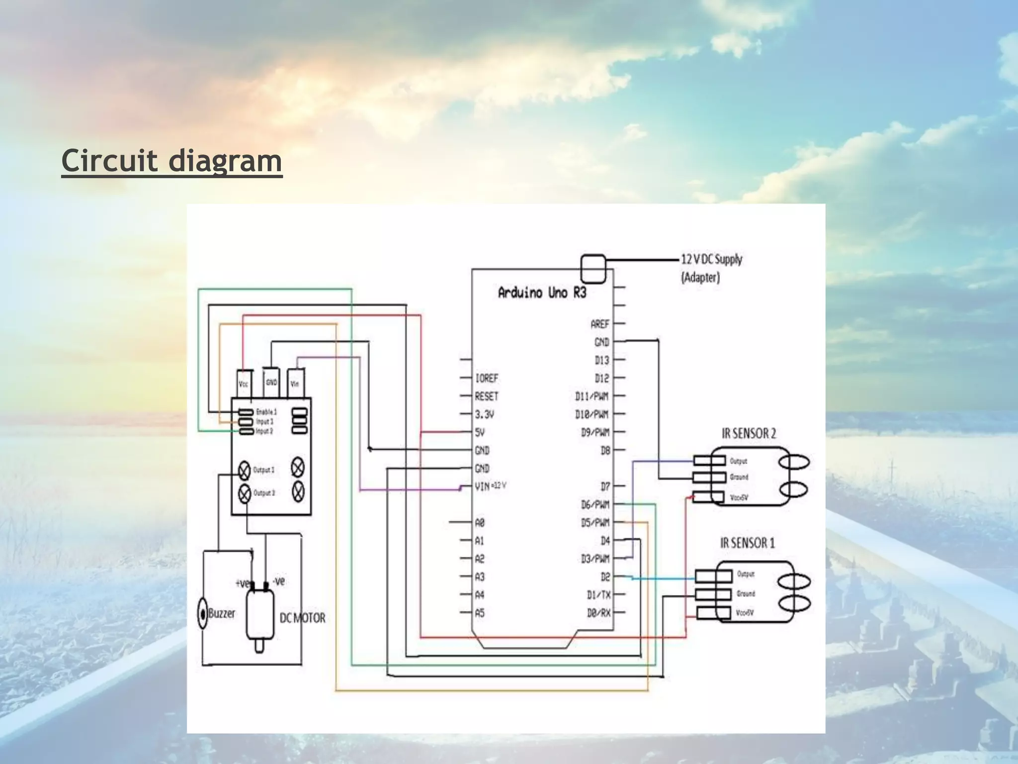
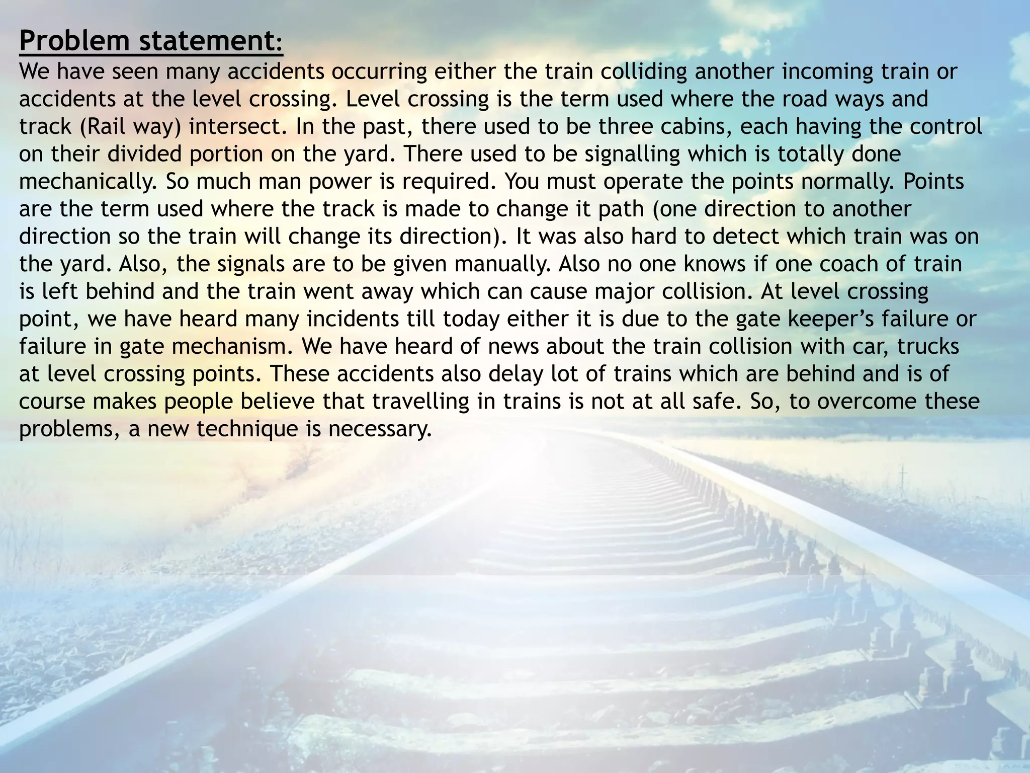
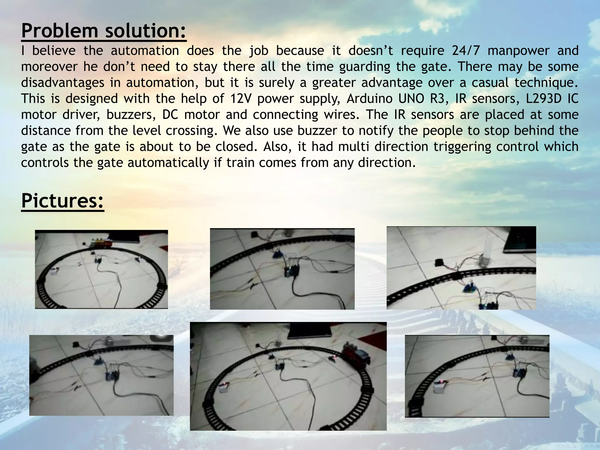
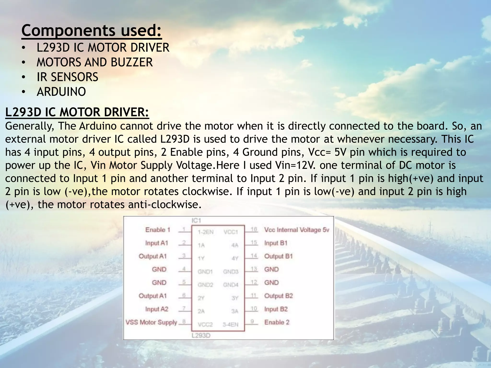
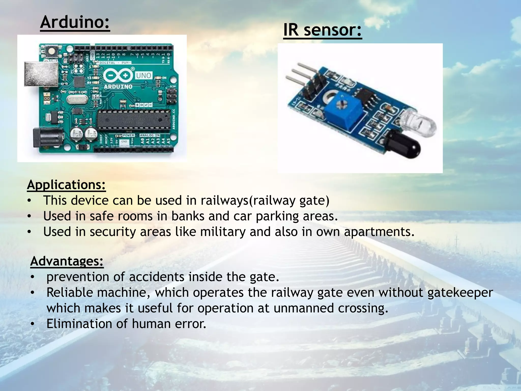
Project Title: AUTOMATIC RAILWAY
GATE CONTROL SYSTEM
Details of team members:
P.Sahithi-17WH1A0442
P.G.vineetha-17WH1A0446
Theerthasree-18WH1A0412
Bhavani-18WH1A0408
Sujatha-17WH1A0402
Collage name: BVRIT Hyderabad collage of engineering for women
Circuit diagram
Problem statement:
We have seen many accidents occurring either the train colliding another incoming train or
accidents at the level crossing. Level crossing is the term used where the road ways and
track (Rail way) intersect. In the past, there used to be three cabins, each having the control
on their divided portion on the yard. There used to be signalling which is totally done
mechanically. So much man power is required. You must operate the points normally. Points
are the term used where the track is made to change it path (one direction to another
direction so the train will change its direction). It was also hard to detect which train was on
the yard. Also, the signals are to be given manually. Also no one knows if one coach of train
is left behind and the train went away which can cause major collision. At level crossing
point, we have heard many incidents till today either it is due to the gate keeper’s failure or
failure in gate mechanism. We have heard of news about the train collision with car, trucks
at level crossing points. These accidents also delay lot of trains which are behind and is of
course makes people believe that travelling in trains is not at all safe. So, to overcome these
problems, a new technique is necessary.
Problem solution:
I believe the automation does the job because it doesn’t require 24/7 manpower and
moreover he don’t need to stay there all the time guarding the gate. There may be some
disadvantages in automation, but it is surely a greater advantage over a casual technique.
This is designed with the help of 12V power supply, Arduino UNO R3, IR sensors, L293D IC
motor driver, buzzers, DC motor and connecting wires. The IR sensors are placed at some
distance from the level crossing. We also use buzzer to notify the people to stop behind the
gate as the gate is about to be closed. Also, it had multi direction triggering control which
controls the gate automatically if train comes from any direction.
Pictures:
Components used:
• L293D IC MOTOR DRIVER
• MOTORS AND BUZZER
• IR SENSORS
• ARDUINO
L293D IC MOTOR DRIVER:
Generally, The Arduino cannot drive the motor when it is directly connected to the board. So, an
external motor driver IC called L293D is used to drive the motor at whenever necessary. This IC
has 4 input pins, 4 output pins, 2 Enable pins, 4 Ground pins, Vcc= 5V pin which is required to
power up the IC, Vin Motor Supply Voltage.Here I used Vin=12V. one terminal of DC motor is
connected to Input 1 pin and another terminal to Input 2 pin. If input 1 pin is high(+ve) and input
2 pin is low (-ve),the motor rotates clockwise. If input 1 pin is low(-ve) and input 2 pin is high
(+ve), the motor rotates anti-clockwise.
Arduino: IR sensor:
Applications:
• This device can be used in railways(railway gate)
• Used in safe rooms in banks and car parking areas.
• Used in security areas like military and also in own apartments.
Advantages:
• prevention of accidents inside the gate.
• Reliable machine, which operates the railway gate even without gatekeeper
which makes it useful for operation at unmanned crossing.
• Elimination of human error.
Automatic railway gate control system

Automatic railway gate control system

  • 1.
    Project Title: AUTOMATICRAILWAY GATE CONTROL SYSTEM Details of team members: P.Sahithi-17WH1A0442 P.G.vineetha-17WH1A0446 Theerthasree-18WH1A0412 Bhavani-18WH1A0408 Sujatha-17WH1A0402 Collage name: BVRIT Hyderabad collage of engineering for women
  • 2.
  • 3.
    Problem statement: We haveseen many accidents occurring either the train colliding another incoming train or accidents at the level crossing. Level crossing is the term used where the road ways and track (Rail way) intersect. In the past, there used to be three cabins, each having the control on their divided portion on the yard. There used to be signalling which is totally done mechanically. So much man power is required. You must operate the points normally. Points are the term used where the track is made to change it path (one direction to another direction so the train will change its direction). It was also hard to detect which train was on the yard. Also, the signals are to be given manually. Also no one knows if one coach of train is left behind and the train went away which can cause major collision. At level crossing point, we have heard many incidents till today either it is due to the gate keeper’s failure or failure in gate mechanism. We have heard of news about the train collision with car, trucks at level crossing points. These accidents also delay lot of trains which are behind and is of course makes people believe that travelling in trains is not at all safe. So, to overcome these problems, a new technique is necessary.
  • 4.
    Problem solution: I believethe automation does the job because it doesn’t require 24/7 manpower and moreover he don’t need to stay there all the time guarding the gate. There may be some disadvantages in automation, but it is surely a greater advantage over a casual technique. This is designed with the help of 12V power supply, Arduino UNO R3, IR sensors, L293D IC motor driver, buzzers, DC motor and connecting wires. The IR sensors are placed at some distance from the level crossing. We also use buzzer to notify the people to stop behind the gate as the gate is about to be closed. Also, it had multi direction triggering control which controls the gate automatically if train comes from any direction. Pictures:
  • 5.
    Components used: • L293DIC MOTOR DRIVER • MOTORS AND BUZZER • IR SENSORS • ARDUINO L293D IC MOTOR DRIVER: Generally, The Arduino cannot drive the motor when it is directly connected to the board. So, an external motor driver IC called L293D is used to drive the motor at whenever necessary. This IC has 4 input pins, 4 output pins, 2 Enable pins, 4 Ground pins, Vcc= 5V pin which is required to power up the IC, Vin Motor Supply Voltage.Here I used Vin=12V. one terminal of DC motor is connected to Input 1 pin and another terminal to Input 2 pin. If input 1 pin is high(+ve) and input 2 pin is low (-ve),the motor rotates clockwise. If input 1 pin is low(-ve) and input 2 pin is high (+ve), the motor rotates anti-clockwise.
  • 6.
    Arduino: IR sensor: Applications: •This device can be used in railways(railway gate) • Used in safe rooms in banks and car parking areas. • Used in security areas like military and also in own apartments. Advantages: • prevention of accidents inside the gate. • Reliable machine, which operates the railway gate even without gatekeeper which makes it useful for operation at unmanned crossing. • Elimination of human error.