Downloaded 1,023 times
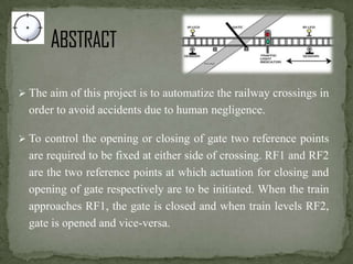
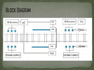


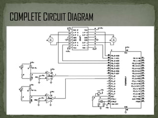


This document describes an automated railway gate controller project that uses infrared transmitters and receivers to automatically open and close railway gates based on the presence of an approaching train. When the train approaches the first reference point, the gate closes, and when the train passes the second reference point, the gate opens. The system utilizes amplitude shift keying modulation at 434MHz and a baud rate of 4800bps. An AT89S8253 microcontroller controls an IR transmitter LED and receiver to open and close the gate motor as trains pass through. The system aims to eliminate human error at unmanned railway crossings and reduce accidents.


![automaticrailwaygatecontrolusingarduinouno-200115134737[1].pptx](https://cdn.slidesharecdn.com/ss_thumbnails/automaticrailwaygatecontrolusingarduinouno-2001151347371-250826175600-5d686697-thumbnail.jpg?width=640&height=640&fit=bounds)