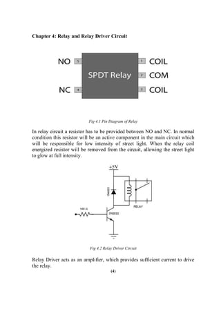
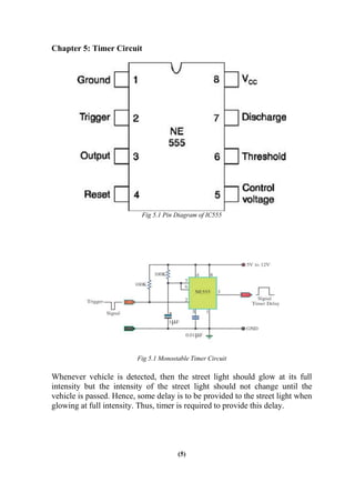
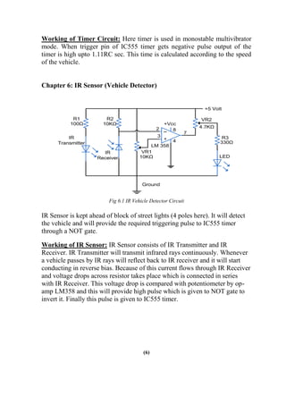
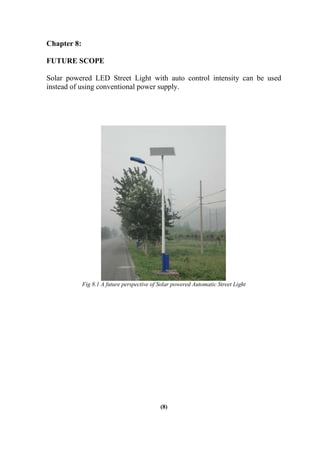
DESIGN AND IMPLEMENTATION OF AUTOMATIC
STREET LIGHT CONTROLLER
A Mini Project-1 Report
Submitted in Partial Fulfillment of the Requirements for the Degree
of
BACHELOR OF TECHNOLOGY
IN
ELECTRICAL ENGINEERING
By
Vasav Shethna (13bee110)
Tushar Shingala (13bee111)
Under the Guidance of
Prof. Manisha Shah
DEPARTMENT OF ELECTRICAL ENGINEERING
INSTITUTE OF TECHNOLOGY
NIRMA UNIVERSITY
Ahmedabad 382 481
November 2015
INSTITUTE OF TECHNOLOGY
NIRMA UNIVERSITY
DEPARTMENT OF ELECTRICAL ENGINEERING
AHMEDABAD – 382481
CERTIFICATE
THIS IS TO CERTIFY THAT THE MINI PROJECT-1 REPORT ENTITLED “ DESIGN AND
IMPLEMENTATION OF AUTOMATIC STREET LIGHT CONTROLLER ” SUBMITTED BY MR./MS.
VASAV SHETHNA (13BEE110) & TUSHAR SHINGALA (13BEE111)
TOWARDS THE PARTIAL FULFILLMENT OF THE REQUIREMENTS FOR THE AWARD OF THE DEGREE IN
BACHELOR OF TECHNOLOGY (ELECTRICAL ENGINEERING) OF NIRMA UNIVERSITY IS
THE RECORD OF WORK CARRIED OUT BY HIM/HER UNDER MY/OUR SUPERVISION AND GUIDANCE.
THE WORK SUBMITTED HAS IN OUR OPINION REACHED A LEVEL REQUIRED FOR BEING ACCEPTED
FOR EXAMINATION.
DATE: 6/11/2015
PROF. MANISHA SHAH
NAME AND SIGNATURE OF
GUIDE
PROF. (DR.) P.N.TEKWANI
HOD(EE)
ACKNOWLEDGEMENT
We have immense pleasure in successful completion of the work titled:
“DESIGN AND IMPLEMENTATION OF AUTOMATIC STREET LIGHT
CONTROLLER”. The special environment at Nirma University, Institute of
Technology, Ahmedabad that always supports educational activities,
facilitated our work on this presentation.
We greatly appreciate the motivation and understanding extended for the
presentation, by Prof. Manisha Shah and Prof. Dhiren Rathod, who
responded promptly and enthusiastically to our requests for expertise, despite
their congested schedules. We are indebted to all of them, who did their best
to bring improvements through their suggestions.
We thank our Dearest Parents, who encouraged us to extend our reach. With
their help and support, we have been able to complete this work.
(I)
ABSTRACT
Street lights are the major requirement in today's life of transportation for
safety purposes and avoiding accidents during night. In today's busy life no
one cares to switch on/off street lights as per the requirement. This project
focuses on saving electricity by detecting the movement of the vehicle on the
road and automatically switches on/off a block of street lights ahead of
vehicle.
Initially the intensity of street light is low, but whenever a vehicle is detected
then the street light glows to its full intensity. After the passage of the
vehicle it again goes back to its initial condition.
In this report an overview of the circuit for the same is explained along with
difficulties still encountered in practical implementation.
(II)
LIST OF CIRCUIT DIAGRAMS
Figure 1.1 LED Street Poles
Figure 2.1 LDR Circuit
Figure 3.1 Linear Power Supply
Figure 4.1 Pin Diagram of Relay
Figure 4.2 Relay Driver Circuit
Figure 5.1 Pin Diagram of IC555 Timer
Figure 5.2 Monostable Timer Circuit
Figure 6.1 IR Vehicle Detector Circuit
Figure 8.1 A future perspective of Solar powered Automatic Street Light
(III)
NOMENCLATURE/ABBREVIATIONS
LDR – Light Dependent Resistor
BJT – Bipolar Junction Transistor
LED – Light Emitting Diode
NO – Normally Open
NC – Normally Close
IR Sensor – InfraRed Sensor
ASLC – Automatic Street Light Control
(IV)
CONTENTS
Acknowledgement (I)
Abstract (II)
List of Figures/Tables (III)
Nomenclature/Abbreviations (IV)
Table of Contents
Chapter 1: Introduction (1)
Chapter 2: LDR circuit (2)
Chapter 3: Linear Power Supply (3)
Chapter 4: Relay and Relay Driver Circuit (4)
Chapter 5: Timer Circuit
Chapter 6: IR Sensor
Chapter 7: Advantages and Disadvantages of ASLC
Chapter 8: Future Scope
Conclusion
(5)
(6)
(7)
(8)
(9)
References (10)
CHAPTER 1: INTRODUCTION
Fig1.1 LED STREET POLES
THIS PROJECT REQUIRES TWO BASIC COMPONENTS I.E. LDR AND SENSORSThe
main consideration in the present field technologies are Automation, Power
consumption and cost effectiveness. Automation is intended to reduce man
power with the help of intelligent systems.
(1)
Chapter 2: LDR Circuit
Fig 2.1 LDR Circuit
During daytime there is no requirement of street lights so the LDR keeps the
street light off until the light level is low or the frequency of light is low the
resistance of the LDR is high. this prevents current from flowing to the base
of the transistors. thus the street lights do not glow. as soon as the light level
goes high or if light falling on the device is of high enough frequency,
photons absorbed by the semiconductor give bound electrons enough energy
to jump into the conduction band. the resulting free electron (and its hole
partner) conduct electricity, thereby lowering resistance.
(2)
Chapter 3: Linear Power Supply
Fig 3.1 Linear Power Supply
Linear Power Supply is required to supply constant DC voltage for the proper
functioning of the circuit.
Working of Linear Power Supply: First of all, the transformer step down
the normal 230V to 12V. The secondary of the transformer is connected to
the diode bridge rectifier which gives pulsating DC. The capacitor filters this
pulsating DC to nearly constant DC of 17V. Linear Voltage Regulator
LM7805 regulates this 17V DC to constant 5V output.
(3)
Chapter 4: Relay and Relay Driver Circuit
Fig 4.1 Pin Diagram of Relay
In relay circuit a resistor has to be provided between NO and NC. In normal
condition this resistor will be an active component in the main circuit which
will be responsible for low intensity of street light. When the relay coil
energized resistor will be removed from the circuit, allowing the street light
to glow at full intensity.
Fig 4.2 Relay Driver Circuit
Relay Driver acts as an amplifier, which provides sufficient current to drive
the relay.
(4)
Chapter 5: Timer Circuit
Fig 5.1 Pin Diagram of IC555
Fig 5.1 Monostable Timer Circuit
Whenever vehicle is detected, then the street light should glow at its full
intensity but the intensity of the street light should not change until the
vehicle is passed. Hence, some delay is to be provided to the street light when
glowing at full intensity. Thus, timer is required to provide this delay.
(5)
Working of Timer Circuit: Here timer is used in monostable multivibrator
mode. When trigger pin of IC555 timer gets negative pulse output of the
timer is high upto 1.11RC sec. This time is calculated according to the speed
of the vehicle.
Chapter 6: IR Sensor (Vehicle Detector)
Fig 6.1 IR Vehicle Detector Circuit
IR Sensor is kept ahead of block of street lights (4 poles here). It will detect
the vehicle and will provide the required triggering pulse to IC555 timer
through a NOT gate.
Working of IR Sensor: IR Sensor consists of IR Transmitter and IR
Receiver. IR Transmitter will transmit infrared rays continuously. Whenever
a vehicle passes by IR rays will reflect back to IR receiver and it will start
conducting in reverse bias. Because of this current flows through IR Receiver
and voltage drops across resistor takes place which is connected in series
with IR Receiver. This voltage drop is compared with potentiometer by op-
amp LM358 and this will provide high pulse which is given to NOT gate to
invert it. Finally this pulse is given to IC555 timer.
(6)
Chapter 7:
ADVANTAGES OF AUTOMATIC STREET LIGHT CONTROL
(1) By using automated street light control, we can reduce the energy
consumption. In manually operated street light it sometimes happen that
street lights are not switched off even though sunlight is there.
(2) Also street lights will on/off according to the sunny and rainy days. So it
reduced the dependency on manual operation.
(3) Circuit is reliable.
(4) It is fit and forget system.
(5) Complete elimination of manpower.
DISADVANTAGES OF AUTOMATIC STREET LIGHT CONTROL
(1) Sensitive to ambient light and requires careful shielding.
(2) Initial cost of investment is high.
(3) In practical implementation the circuit turns out to be much more
complex as it contains different sub-circuits.
(4) Sometimes it may happen that due to malfunction of IR sensor the street
light may not be able to glow at its full intensity.
(7)
Chapter 8:
FUTURE SCOPE
Solar powered LED Street Light with auto control intensity can be used
instead of using conventional power supply.
Fig 8.1 A future perspective of Solar powered Automatic Street Light
(8)
Conclusion
This project of AUTOMATIC STREET LIGHTS is a cost effective, practical
ecofriendly and the safest way to save energy. It clearly tackles the two
problems that world is facing today, saving of energy and also disposal of
incandescent lamps, very efficiently. According to statistical data we can
save more that 40 % of electrical energy that is now consumed by the
highways. Initial cost and maintenance can be the draw backs of this project.
With the advances in technology and good resource planning the cost of the
project can be cut down and also with the use of good equipment the
maintenance can also be reduced in terms of periodic checks. The LEDs
have long life, emit cool light, donor have any toxic material and can be used
for fast switching. For these reasons this project presents far more advantages
which can over come the present limitations. Keeping in view the long term
benefits and the initial cost would never be a problem as the investment
return time is very less.
(9)
References:
[1] Caponetto, R., Dongola, G., Fortuna, L., Riscica, N. and Zufacchi, D.
(2008), “Power consumption reduction in a remote controlled street lighting
system”, International Symposium on Power Electronics, Electrical Drives,
Automation and Motion.
[2] Sensors: Advancements in Modeling, Design Issues, Fabrication and
Practical by Subhas Chandra.
[3]HTTP://MICROCONTROLLERSLAB.COM/AUTOMATIC-CONTROL-OF-STREET-
LIGHTS/
[4] HTTP://WWW.ENGINEERSGARAGE.COM/FORUMS/8051/INTELLIGENT-STREET-
LIGHTING-SYSTEM-USING-8051
(10)
Mini-Project-1 Report

Mini-Project-1 Report

  • 1.
    DESIGN AND IMPLEMENTATIONOF AUTOMATIC STREET LIGHT CONTROLLER A Mini Project-1 Report Submitted in Partial Fulfillment of the Requirements for the Degree of BACHELOR OF TECHNOLOGY IN ELECTRICAL ENGINEERING By Vasav Shethna (13bee110) Tushar Shingala (13bee111) Under the Guidance of Prof. Manisha Shah DEPARTMENT OF ELECTRICAL ENGINEERING INSTITUTE OF TECHNOLOGY NIRMA UNIVERSITY Ahmedabad 382 481 November 2015
  • 2.
    INSTITUTE OF TECHNOLOGY NIRMAUNIVERSITY DEPARTMENT OF ELECTRICAL ENGINEERING AHMEDABAD – 382481 CERTIFICATE THIS IS TO CERTIFY THAT THE MINI PROJECT-1 REPORT ENTITLED “ DESIGN AND IMPLEMENTATION OF AUTOMATIC STREET LIGHT CONTROLLER ” SUBMITTED BY MR./MS. VASAV SHETHNA (13BEE110) & TUSHAR SHINGALA (13BEE111) TOWARDS THE PARTIAL FULFILLMENT OF THE REQUIREMENTS FOR THE AWARD OF THE DEGREE IN BACHELOR OF TECHNOLOGY (ELECTRICAL ENGINEERING) OF NIRMA UNIVERSITY IS THE RECORD OF WORK CARRIED OUT BY HIM/HER UNDER MY/OUR SUPERVISION AND GUIDANCE. THE WORK SUBMITTED HAS IN OUR OPINION REACHED A LEVEL REQUIRED FOR BEING ACCEPTED FOR EXAMINATION. DATE: 6/11/2015 PROF. MANISHA SHAH NAME AND SIGNATURE OF GUIDE PROF. (DR.) P.N.TEKWANI HOD(EE)
  • 3.
    ACKNOWLEDGEMENT We have immensepleasure in successful completion of the work titled: “DESIGN AND IMPLEMENTATION OF AUTOMATIC STREET LIGHT CONTROLLER”. The special environment at Nirma University, Institute of Technology, Ahmedabad that always supports educational activities, facilitated our work on this presentation. We greatly appreciate the motivation and understanding extended for the presentation, by Prof. Manisha Shah and Prof. Dhiren Rathod, who responded promptly and enthusiastically to our requests for expertise, despite their congested schedules. We are indebted to all of them, who did their best to bring improvements through their suggestions. We thank our Dearest Parents, who encouraged us to extend our reach. With their help and support, we have been able to complete this work. (I)
  • 4.
    ABSTRACT Street lights arethe major requirement in today's life of transportation for safety purposes and avoiding accidents during night. In today's busy life no one cares to switch on/off street lights as per the requirement. This project focuses on saving electricity by detecting the movement of the vehicle on the road and automatically switches on/off a block of street lights ahead of vehicle. Initially the intensity of street light is low, but whenever a vehicle is detected then the street light glows to its full intensity. After the passage of the vehicle it again goes back to its initial condition. In this report an overview of the circuit for the same is explained along with difficulties still encountered in practical implementation. (II)
  • 5.
    LIST OF CIRCUITDIAGRAMS Figure 1.1 LED Street Poles Figure 2.1 LDR Circuit Figure 3.1 Linear Power Supply Figure 4.1 Pin Diagram of Relay Figure 4.2 Relay Driver Circuit Figure 5.1 Pin Diagram of IC555 Timer Figure 5.2 Monostable Timer Circuit Figure 6.1 IR Vehicle Detector Circuit Figure 8.1 A future perspective of Solar powered Automatic Street Light (III)
  • 6.
    NOMENCLATURE/ABBREVIATIONS LDR – LightDependent Resistor BJT – Bipolar Junction Transistor LED – Light Emitting Diode NO – Normally Open NC – Normally Close IR Sensor – InfraRed Sensor ASLC – Automatic Street Light Control (IV)
  • 7.
    CONTENTS Acknowledgement (I) Abstract (II) Listof Figures/Tables (III) Nomenclature/Abbreviations (IV) Table of Contents Chapter 1: Introduction (1) Chapter 2: LDR circuit (2) Chapter 3: Linear Power Supply (3) Chapter 4: Relay and Relay Driver Circuit (4) Chapter 5: Timer Circuit Chapter 6: IR Sensor Chapter 7: Advantages and Disadvantages of ASLC Chapter 8: Future Scope Conclusion (5) (6) (7) (8) (9) References (10)
  • 8.
    CHAPTER 1: INTRODUCTION Fig1.1LED STREET POLES THIS PROJECT REQUIRES TWO BASIC COMPONENTS I.E. LDR AND SENSORSThe main consideration in the present field technologies are Automation, Power consumption and cost effectiveness. Automation is intended to reduce man power with the help of intelligent systems. (1)
  • 9.
    Chapter 2: LDRCircuit Fig 2.1 LDR Circuit During daytime there is no requirement of street lights so the LDR keeps the street light off until the light level is low or the frequency of light is low the resistance of the LDR is high. this prevents current from flowing to the base of the transistors. thus the street lights do not glow. as soon as the light level goes high or if light falling on the device is of high enough frequency, photons absorbed by the semiconductor give bound electrons enough energy to jump into the conduction band. the resulting free electron (and its hole partner) conduct electricity, thereby lowering resistance. (2)
  • 10.
    Chapter 3: LinearPower Supply Fig 3.1 Linear Power Supply Linear Power Supply is required to supply constant DC voltage for the proper functioning of the circuit. Working of Linear Power Supply: First of all, the transformer step down the normal 230V to 12V. The secondary of the transformer is connected to the diode bridge rectifier which gives pulsating DC. The capacitor filters this pulsating DC to nearly constant DC of 17V. Linear Voltage Regulator LM7805 regulates this 17V DC to constant 5V output. (3)
  • 11.
    Chapter 4: Relayand Relay Driver Circuit Fig 4.1 Pin Diagram of Relay In relay circuit a resistor has to be provided between NO and NC. In normal condition this resistor will be an active component in the main circuit which will be responsible for low intensity of street light. When the relay coil energized resistor will be removed from the circuit, allowing the street light to glow at full intensity. Fig 4.2 Relay Driver Circuit Relay Driver acts as an amplifier, which provides sufficient current to drive the relay. (4)
  • 12.
    Chapter 5: TimerCircuit Fig 5.1 Pin Diagram of IC555 Fig 5.1 Monostable Timer Circuit Whenever vehicle is detected, then the street light should glow at its full intensity but the intensity of the street light should not change until the vehicle is passed. Hence, some delay is to be provided to the street light when glowing at full intensity. Thus, timer is required to provide this delay. (5)
  • 13.
    Working of TimerCircuit: Here timer is used in monostable multivibrator mode. When trigger pin of IC555 timer gets negative pulse output of the timer is high upto 1.11RC sec. This time is calculated according to the speed of the vehicle. Chapter 6: IR Sensor (Vehicle Detector) Fig 6.1 IR Vehicle Detector Circuit IR Sensor is kept ahead of block of street lights (4 poles here). It will detect the vehicle and will provide the required triggering pulse to IC555 timer through a NOT gate. Working of IR Sensor: IR Sensor consists of IR Transmitter and IR Receiver. IR Transmitter will transmit infrared rays continuously. Whenever a vehicle passes by IR rays will reflect back to IR receiver and it will start conducting in reverse bias. Because of this current flows through IR Receiver and voltage drops across resistor takes place which is connected in series with IR Receiver. This voltage drop is compared with potentiometer by op- amp LM358 and this will provide high pulse which is given to NOT gate to invert it. Finally this pulse is given to IC555 timer. (6)
  • 14.
    Chapter 7: ADVANTAGES OFAUTOMATIC STREET LIGHT CONTROL (1) By using automated street light control, we can reduce the energy consumption. In manually operated street light it sometimes happen that street lights are not switched off even though sunlight is there. (2) Also street lights will on/off according to the sunny and rainy days. So it reduced the dependency on manual operation. (3) Circuit is reliable. (4) It is fit and forget system. (5) Complete elimination of manpower. DISADVANTAGES OF AUTOMATIC STREET LIGHT CONTROL (1) Sensitive to ambient light and requires careful shielding. (2) Initial cost of investment is high. (3) In practical implementation the circuit turns out to be much more complex as it contains different sub-circuits. (4) Sometimes it may happen that due to malfunction of IR sensor the street light may not be able to glow at its full intensity. (7)
  • 15.
    Chapter 8: FUTURE SCOPE Solarpowered LED Street Light with auto control intensity can be used instead of using conventional power supply. Fig 8.1 A future perspective of Solar powered Automatic Street Light (8)
  • 16.
    Conclusion This project ofAUTOMATIC STREET LIGHTS is a cost effective, practical ecofriendly and the safest way to save energy. It clearly tackles the two problems that world is facing today, saving of energy and also disposal of incandescent lamps, very efficiently. According to statistical data we can save more that 40 % of electrical energy that is now consumed by the highways. Initial cost and maintenance can be the draw backs of this project. With the advances in technology and good resource planning the cost of the project can be cut down and also with the use of good equipment the maintenance can also be reduced in terms of periodic checks. The LEDs have long life, emit cool light, donor have any toxic material and can be used for fast switching. For these reasons this project presents far more advantages which can over come the present limitations. Keeping in view the long term benefits and the initial cost would never be a problem as the investment return time is very less. (9)
  • 17.
    References: [1] Caponetto, R.,Dongola, G., Fortuna, L., Riscica, N. and Zufacchi, D. (2008), “Power consumption reduction in a remote controlled street lighting system”, International Symposium on Power Electronics, Electrical Drives, Automation and Motion. [2] Sensors: Advancements in Modeling, Design Issues, Fabrication and Practical by Subhas Chandra. [3]HTTP://MICROCONTROLLERSLAB.COM/AUTOMATIC-CONTROL-OF-STREET- LIGHTS/ [4] HTTP://WWW.ENGINEERSGARAGE.COM/FORUMS/8051/INTELLIGENT-STREET- LIGHTING-SYSTEM-USING-8051 (10)