Download to read offline
![ZERO TURNING RADIUS STRETCHER
A Project Submitted in Partial Fulfillment of the Requirement for the Award of the Degree
BACHELOR OF TECHNOLOGY
MECHANICAL ENGINEERING
RIZWAN SEIKH
AKASH KUMAR SINGH (ID No. 175126
VINOD KUMAR YADAV (ID No. 175105
NIDHI YADAV (ID No. 175139
Mr. HIMANSHU TIWARI
Department of Mechanical
Uma Nath Singh Institute of Engineering & Technology
VEER BAHADUR SINGH PURVANCHAL
JAUNPUR, UTTAR PRADESH
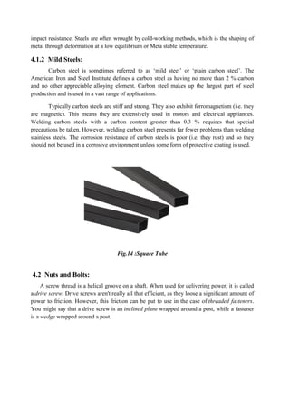
ZERO TURNING RADIUS STRETCHER
Project Submitted in Partial Fulfillment of the Requirement for the Award of the Degree
BACHELOR OF TECHNOLOGY
in
MECHANICAL ENGINEERING
Submitted By
RIZWAN SEIKH (ID No. 175150)
AKASH KUMAR SINGH (ID No. 175126)
VINOD KUMAR YADAV (ID No. 175105)
NIDHI YADAV (ID No. 175139)
Under the Supervision of
Mr. HIMANSHU TIWARI
(Assistant Professor)
Department of Mechanical Engineering
ath Singh Institute of Engineering & Technology
VEER BAHADUR SINGH PURVANCHAL UNIVERSITY
JAUNPUR, UTTAR PRADESH
[2017-2021]
Project Submitted in Partial Fulfillment of the Requirement for the Award of the Degree of
ath Singh Institute of Engineering & Technology
UNIVERSITY](https://image.slidesharecdn.com/zeroturningradiusstretcher-210720132816/85/ZERO-TURNING-RADIUS-STRETCHER-ZTRS-1-320.jpg)
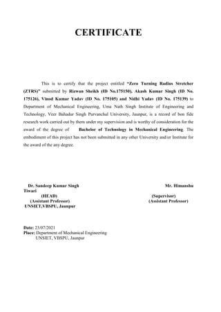

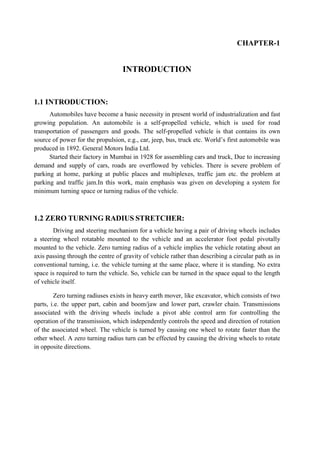
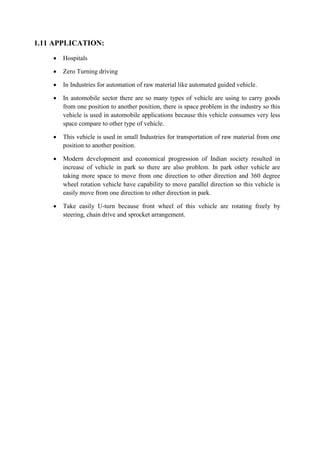
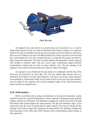
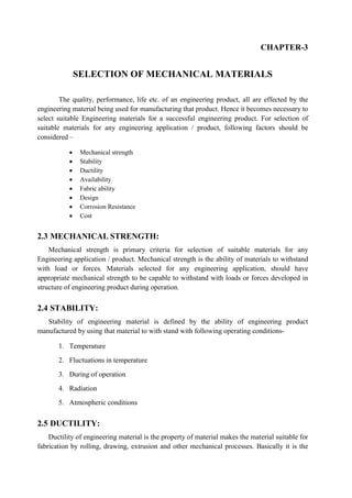
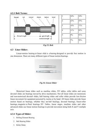
![2.2.3 Pliers:
Pliers are a hand tool used to hold objects firmly, possibly developed from tongs used
to handle hot metal in Bronze Age Europe.[1]
They are also useful
for bending and compressing a wide range of materials. Generally, pliers consist of a pair
of metal first-class levers joined at a fulcrum positioned closer to one end of the levers,
creating short jaws on one side of the fulcrum, and longer handles on the other side.[1]
This
arrangement creates a mechanical advantage, allowing the force of the hand's grip to be
amplified and focused on an object with precision. The jaws can also be used to manipulate
objects too small or unwieldy to be manipulated with the fingers.
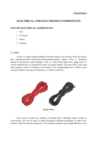
Fig.4: Pliers
Pincers are a similar tool with a different type of head used for cutting and pulling,
rather than squeezing. Tools designed for safely handling hot objects are usually called tongs.
Special tools for making crimp connections in electrical and electronic applications are often
called "crimping pliers"; each type of connection uses its own dedicated tool.
2.2.4 Hammer:
A hammer is a tool or device that delivers a blow (a sudden impact) to an object. Most
hammers are hand tools used to drive nails, fit parts, forge metal, and break apart objects.
Hammers vary in shape, size, and structure, depending on their purposes.
Hammers are basic tools in many trades. The usual features are a head (most often
made of steel) and a handle (also called a helve or haft). Although most hammers are hand
tools, powered versions exist; they are known as powered hammers. Types of power hammer
include steam hammers and trip hammers, often for heavier uses, such as forging.](https://image.slidesharecdn.com/zeroturningradiusstretcher-210720132816/85/ZERO-TURNING-RADIUS-STRETCHER-ZTRS-14-320.jpg)
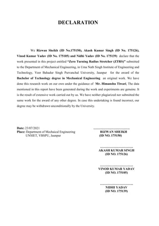
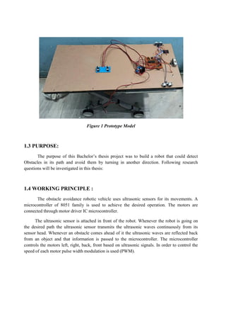
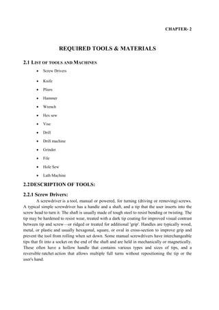
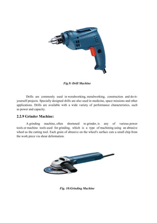
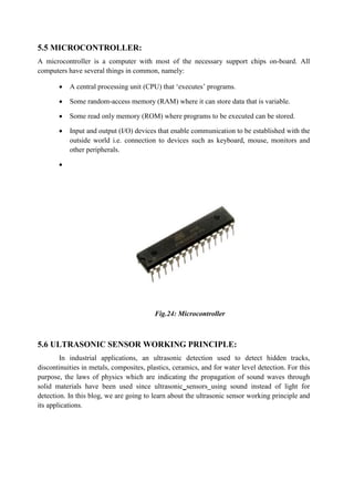
![Fig.5: Hammer
Some hammers have other names, such as sledgehammer, mallet and gavel. The term
"hammer" also applies to devices that deliver blows, such as the hammer of a firearm or the
hammer of a piano or the hammer ice scraper.
2.2.5 Wrench:
A wrench (or spanner outside of North America) is a tool used to provide grip
and mechanical advantage in applying torque to turn objects—usually rotary fasteners, such
as nuts and bolts or keep them from turning.
In Commonwealth English (excluding Canada), spanner is the standard term. The most
common shapes are called open-ended spanner and ring spanner. The term wrench is
generally used for tools that turn non-fastening devices (e.g. tap wrench and pipe wrench), or
may be used for a monkey wrench - an adjustable spanner.[1]
In North American English, wrench is the standard term. The most common shapes are
called open-end wrench and box-end wrench. In American English, spanner refers to a
specialised wrench with a series of pins or tabs around the circumference. (These pins or tabs
fit into the holes or notches cut into the object to be turned.) In American commerce, such a
wrench may be called a spanner wrench to distinguish it from the British sense of spanner.
Fig.6: Wrench](https://image.slidesharecdn.com/zeroturningradiusstretcher-210720132816/85/ZERO-TURNING-RADIUS-STRETCHER-ZTRS-15-320.jpg)
![Solder melts at approximately 185°C (365°F). Soldering irons are designed to reach a
temperature range of 200° to 480°C (392° to 896° F).Soldering
installation, repairs, and limited production work in electronics assembly. High
production lines use other soldering methods.
sheet metal objects. Less common uses inc
and plastic welding(Ultrasonic welding
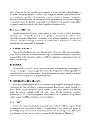
2.3.2 Solder:
Solder or in North America
between metal work pieces. Solder is melted in order to adhere to and connect the pieces after
cooling, which requires that an alloy suitable for use as solder have a lower melting
the pieces being joined. The solder should also be resistant to oxidative and corrosive effects
that would degrade the joint over time. Solder used in making electrical connections also needs
to have favourable electrical characteristics.
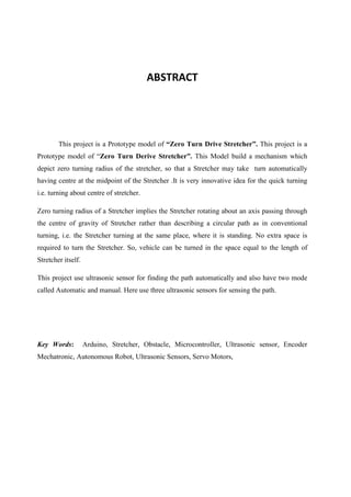
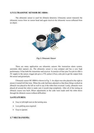
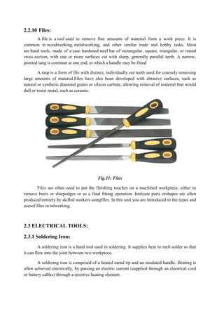
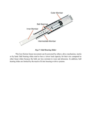
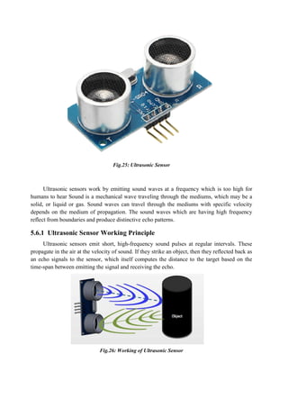
Solder melts at approximately 185°C (365°F). Soldering irons are designed to reach a
temperature range of 200° to 480°C (392° to 896° F).Soldering irons are most often used for
installation, repairs, and limited production work in electronics assembly. High
production lines use other soldering methods.[1]
Large irons may be used for soldering joints in
sheet metal objects. Less common uses include pyrography (burning designs into wood)
plastic welding(Ultrasonic welding could possibly be used if set correctly).
Fig.12: Soldering Iron
in North America is a fusible metal alloy used to create a permanent bond
between metal work pieces. Solder is melted in order to adhere to and connect the pieces after
cooling, which requires that an alloy suitable for use as solder have a lower melting
the pieces being joined. The solder should also be resistant to oxidative and corrosive effects
that would degrade the joint over time. Solder used in making electrical connections also needs
to have favourable electrical characteristics.
Solder melts at approximately 185°C (365°F). Soldering irons are designed to reach a
irons are most often used for
installation, repairs, and limited production work in electronics assembly. High-volume
Large irons may be used for soldering joints in
(burning designs into wood)
could possibly be used if set correctly).
used to create a permanent bond
between metal work pieces. Solder is melted in order to adhere to and connect the pieces after
cooling, which requires that an alloy suitable for use as solder have a lower melting point than
the pieces being joined. The solder should also be resistant to oxidative and corrosive effects
that would degrade the joint over time. Solder used in making electrical connections also needs](https://image.slidesharecdn.com/zeroturningradiusstretcher-210720132816/85/ZERO-TURNING-RADIUS-STRETCHER-ZTRS-20-320.jpg)
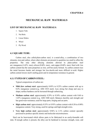
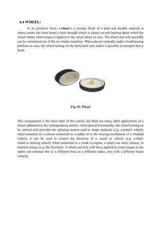
![1. Rolling-element Bearing
Rolling-element A rolling-element bearing is generally composed of a sleeve-like outer
ring and several rows of balls retained by cages. The cages were originally machined from
solid metal and were quickly replaced by stampings. It features smooth motion, low friction,
high rigidity and long life. They are economical, and easy to maintain and replace. Thomson
(currently owned by Danaher) is generally given credit for first producing [what is now known
as] a linear ball bearing.
Rolling-element bearings can only run on hardened steel or stainless steel shafting
(raceways).
bearings are more rigid than plane bearings.
Rolling-element bearings do not handle contamination well and require seals.
2.Ball Bearing Slides
Also called "ball slides", ball bearing slides are the most common type of linear slide.
Ball bearing slides offer smooth precision motion along a single-axis linear design, aided by
ball bearings housed in the linear base, with self-lubrication properties that increase reliability.
Constructed from materials such as Aluminum, hardened cold rolled steel and
galvanized steel, ball bearing slides consist of two linear rows of ball bearings contained by
four rods and located on differing sides of the base, which support the carriage for smooth
linear movement along the ball bearings.Ball bearing slide applications include delicate
instrumentation, robotic assembly, cabinetry, high-end appliances and clean room
environments, which primarily serve the manufacturing industry but also the furniture,
electronics and construction industries. For example, a widely used ball bearing slide in the
furniture industry is a ball bearing drawer slide.](https://image.slidesharecdn.com/zeroturningradiusstretcher-210720132816/85/ZERO-TURNING-RADIUS-STRETCHER-ZTRS-27-320.jpg)
![coils in loudspeakers. Edge-wound
flattened wire.
Electrical wiring is an electrical
distribution boards, sockets, and light fittings in a structure.Wiring is subject to safety
standards for design and installation. Allowable
according to the circuit operating
restrictions on the environmental conditions, such as ambient temperature range, moisture
levels, and exposure to sunlight and chemicals.
Associated circuit protection, control and distribution devices within a building's wiring
system are subject to voltage, curre
5.2 BRUSHED DC ELECTRIC
A brushed DC motor is an internally
from a direct current power source. Brushed motors were the first commercially important
application of electric power to driving mechanical loads, and DC distribution systems were
used for more than 100 years to operate motors in commercial and industrial buildings.
Brushed DC motors can be varied in speed by changing the operating voltage or the s
the magnetic field. Depending on the connections of the field to the power supply, the speed
and torque characteristics of a brushed motor can be altered to provide steady speed or speed
inversely proportional to the mechanical load. Brushed mot
electrical propulsion, cranes, paper machines and steel rolling mills. Since the brushes wear
down and require replacement, brushless motors using
displaced brushed motors from many applications.
wound[1]
coil springs, such as the Slinky toy, are made of special
electrical installation of cabling and associated devices such as switches,
, and light fittings in a structure.Wiring is subject to safety
standards for design and installation. Allowable wire and cable types and sizes are specified
according to the circuit operating voltage and electric current capability, with further
ons on the environmental conditions, such as ambient temperature range, moisture
levels, and exposure to sunlight and chemicals.
Associated circuit protection, control and distribution devices within a building's wiring
system are subject to voltage, current and functional specification. Wiring safety codes vary
ELECTRIC MOTOR:
is an internally commutated electric motor designed to be run
power source. Brushed motors were the first commercially important
ation of electric power to driving mechanical loads, and DC distribution systems were
used for more than 100 years to operate motors in commercial and industrial buildings.
Brushed DC motors can be varied in speed by changing the operating voltage or the s
the magnetic field. Depending on the connections of the field to the power supply, the speed
and torque characteristics of a brushed motor can be altered to provide steady speed or speed
inversely proportional to the mechanical load. Brushed motors continue to be used for
electrical propulsion, cranes, paper machines and steel rolling mills. Since the brushes wear
down and require replacement, brushless motors using power electronic devices
displaced brushed motors from many applications.
Fig.21: DC Geared Motor
toy, are made of special
installation of cabling and associated devices such as switches,
, and light fittings in a structure.Wiring is subject to safety
types and sizes are specified
capability, with further
ons on the environmental conditions, such as ambient temperature range, moisture
Associated circuit protection, control and distribution devices within a building's wiring
nt and functional specification. Wiring safety codes vary
designed to be run
power source. Brushed motors were the first commercially important
ation of electric power to driving mechanical loads, and DC distribution systems were
used for more than 100 years to operate motors in commercial and industrial buildings.
Brushed DC motors can be varied in speed by changing the operating voltage or the strength of
the magnetic field. Depending on the connections of the field to the power supply, the speed
and torque characteristics of a brushed motor can be altered to provide steady speed or speed
ors continue to be used for
electrical propulsion, cranes, paper machines and steel rolling mills. Since the brushes wear
power electronic devices have](https://image.slidesharecdn.com/zeroturningradiusstretcher-210720132816/85/ZERO-TURNING-RADIUS-STRETCHER-ZTRS-32-320.jpg)
![When the armature becomes horizontally aligned, the torque becomes zero. At this point, the
commutator reverses the direction of current through the coil, reversing the magnetic field.
A simple DC electric motor. When the coil is powered, a
armature. The left side of the armature is pushed away from the left
Fig.22
When a current passes through the coil wound
positive pole is acted upon by an upwards force, while the other side is acted upon by a
downward force. According to Fleming's left hand rule
coil, making it rotate. To make the motor rotate in a constant direction, "direct current"
commutator make the current reverse in direction every half a cycle (in a two
causing the motor to continue to rotate in the same direction.
5.3BATTERY:
As they are inexpensive compared to newer technologies, lead
used even when surge current is not important and other designs could provide higher
densities. In 1999 lead–acid battery sales accounted for 40
sold worldwide (excluding China and Russia), equivalent to a manufacturing market value of
about $15 billion.[8]
Large-format lead
power supplies in cell phone towers, high
power systems. For these roles, modified versions of the standard cell may be used to improve
storage times and reduce maintenance requirements.
mat batteries are common in these roles, collectively known as
acid) batteries.
When the armature becomes horizontally aligned, the torque becomes zero. At this point, the
reverses the direction of current through the coil, reversing the magnetic field.
A simple DC electric motor. When the coil is powered, a magnetic field is generated around the
armature. The left side of the armature is pushed away from the left magnet and drawn toward the right,
Fig.22: Brushless DC Electric Motor
When a current passes through the coil wound around a soft iron core, the side of the
positive pole is acted upon by an upwards force, while the other side is acted upon by a
Fleming's left hand rule, the forces cause a turning effect on the
coil, making it rotate. To make the motor rotate in a constant direction, "direct current"
commutator make the current reverse in direction every half a cycle (in a two
causing the motor to continue to rotate in the same direction.
As they are inexpensive compared to newer technologies, lead–acid batteries are widely
used even when surge current is not important and other designs could provide higher
acid battery sales accounted for 40–45% of the value from batteries
sold worldwide (excluding China and Russia), equivalent to a manufacturing market value of
format lead–acid designs are widely used for stora
cell phone towers, high-availability settings like hospitals, and
power systems. For these roles, modified versions of the standard cell may be used to improve
storage times and reduce maintenance requirements. Gel-cells and
batteries are common in these roles, collectively known as VRLA (valve
When the armature becomes horizontally aligned, the torque becomes zero. At this point, the
reverses the direction of current through the coil, reversing the magnetic field.
is generated around the
and drawn toward the right,
around a soft iron core, the side of the
positive pole is acted upon by an upwards force, while the other side is acted upon by a
, the forces cause a turning effect on the
coil, making it rotate. To make the motor rotate in a constant direction, "direct current"
commutator make the current reverse in direction every half a cycle (in a two-pole motor) thus
acid batteries are widely
used even when surge current is not important and other designs could provide higher energy
45% of the value from batteries
sold worldwide (excluding China and Russia), equivalent to a manufacturing market value of
acid designs are widely used for storage in backup
availability settings like hospitals, and stand-alone
power systems. For these roles, modified versions of the standard cell may be used to improve
and absorbed glass-
VRLA (valve-regulated lead–](https://image.slidesharecdn.com/zeroturningradiusstretcher-210720132816/85/ZERO-TURNING-RADIUS-STRETCHER-ZTRS-33-320.jpg)
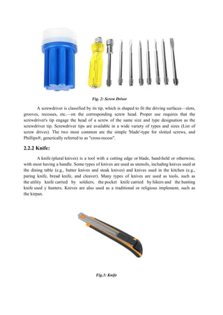
![The lead–acid battery was invented in 1859 by French physicist
earliest type of rechargeable battery. Despite having a very low energy
low energy-to-volume ratio, its ability to supply high
relatively large power-to-weight ratio. These features, along with their low cost, make them
attractive for use in motor vehicles to provide the high current required by
In the charged state, the chemical energy of the battery is stored in the potential
difference between the pure lead at the negative side and
the aqueous sulphuric acid. The electrical energy produced by a discharging lead
can be attributed to the energy released when the strong chemical bonds of water (H
molecules are formed from H
charging, the battery acts as a
batteries such as the Ca–Sb and Sn
LIST OF ELECTRONICS COMPONENTS
1. Microcontroller
2. Ultrasonic Sensors
3. Diode
4. Voltage Regulators
was invented in 1859 by French physicist Gaston Planté
battery. Despite having a very low energy-to-
volume ratio, its ability to supply high surge currents means that the cells have a
weight ratio. These features, along with their low cost, make them
ttractive for use in motor vehicles to provide the high current required by starter motors.
Fig.23: Battery
In the charged state, the chemical energy of the battery is stored in the potential
difference between the pure lead at the negative side and the PbO2 on the positive side, plus
the aqueous sulphuric acid. The electrical energy produced by a discharging lead
can be attributed to the energy released when the strong chemical bonds of water (H
molecules are formed from H+
ions of the acid and O2−
ions of PbO2.[9]
Conversely, during
charging, the battery acts as a water-splitting device. Liquid metal and
Sb and Sn–Bi also use this effect.
LIST OF ELECTRONICS COMPONENTS
Gaston Planté and is the
-weight ratio and a
means that the cells have a
weight ratio. These features, along with their low cost, make them
starter motors.
In the charged state, the chemical energy of the battery is stored in the potential
on the positive side, plus
the aqueous sulphuric acid. The electrical energy produced by a discharging lead–acid battery
can be attributed to the energy released when the strong chemical bonds of water (H2O)
Conversely, during
device. Liquid metal and molten-salt](https://image.slidesharecdn.com/zeroturningradiusstretcher-210720132816/85/ZERO-TURNING-RADIUS-STRETCHER-ZTRS-34-320.jpg)
![REFERENCES
[1] V. Prasannabalaji, R. Rakesh, S. Sairam . “Staircase powergeneration using piezoelectric
transducers”, Advance inElectronic and Electric Engineering, 2013; 3: 747–754p.
[2] G.Dhanalakshmi ,T.Manjulai ,“Footstep Power GenerationSystem” ,International Journal
Of Engineering And ComputerScience, ISSN:2319-7242, Volume 6 Issue 4 April 2017,
PageNo. 21011-21014,
[3] Yogesh Motey, Pooja Dekate, “Footstep Power GenerationSystem”, International Journal
of Innovations in Engineeringand Science, Vol. 2, No.6, 2017.
[4] K.Ramakrishna, Guruswamy Revana, “Generation ofElectrical Power through
Footsteps”, International Journal ofMultidisciplinary and Current Research, ISSN: 2321-
3124.
[5] “Interfacing Piezo Film to Electronics”, Measurement Specialties. March 2006, Retrieved
December 2, 2007.
[6] Alfredo Vazquez Carazo (January 2000), “Novel Piezoelectric Transducers for High
Voltage Measurements”, Universitat Politecnica de Catalunya: 242.
[7] Orcutt, Mike, “Managing Light To Increases Solar Efficiency”, MIT Technology Review,
Retrieved 2018-03-14.
[8] Binoy Boban, Tom Jose v, Sijvo MT , “Electricity generation from footstep ;a Generative
energy Resource’’ International journal of sciventic and research publication 1-3, March
2013](https://image.slidesharecdn.com/zeroturningradiusstretcher-210720132816/85/ZERO-TURNING-RADIUS-STRETCHER-ZTRS-39-320.jpg)
![[9] U.K Singh and R.H. Middleton has developed a system “piezoelectric power scavenging of
mechanical vibration energy” research publication In 4 Oct 2007
[10] Mechatronics (ICOM) ,2011 4th International conference by Fakhazan
,M.N.,Muthalif,A.G.A.](https://image.slidesharecdn.com/zeroturningradiusstretcher-210720132816/85/ZERO-TURNING-RADIUS-STRETCHER-ZTRS-40-320.jpg)

This document describes a project to design a zero turning radius stretcher. A zero turning radius stretcher can turn within its own length, allowing it to maneuver in tight spaces. The project aims to build a prototype model that uses ultrasonic sensors to detect obstacles and allow the stretcher to turn automatically or manually to avoid collisions. The stretcher mechanism will allow it to rotate about its center point for tight turns without needing additional space.