Industrial training report on dlw varanasi for Main Receiving Substation, Tra...Devendra Kumar
Industrial training report on dlw Varanasi for Main Receiving Substation, Traction assembly shop, Maintenance area 2 and Loco Testing Shop(LTS).The industrial training report of DLW (DIESEL LOCOMOTIVE WORKS) is a different trade. i.e. Electronics and Communication, Electrical, Mechanical, Electrical & Electronics and many engineering holders have participated. The content of my industrial topic Main Receiving Substation, TRACTION ASSEMBLY SHOP, Maintenance area 2 and Loco Testing Shop
this is ppt based on my 4 weeks training at D.L.W varanasi I have included brief introduction along with introduction and working of various shops hope you will find helpful
DLW SUMMER TRAINING REPORT FOR ECE BRANCH SUBHAM SINGH
this report is very usful for student who are doing in a DLW summer training and also learns a lot of thing from this report .I have learnt a lot of things from DLW training and i feel lucky to this part of summer training in a DLW ,varanasi .And last things,I suggest to all of u ,please dont do training for attendance purpose ,honestly u should learn a lot of things which is better for ur future.DLW is an integrated plant and its manufacturing facilities are flexible in nature.
DLW is an integrated plant and its manufacturing facilities are flexible in nature. These can be utilized for manufacture of different design of locomotives of various gauges suiting customer requirements and other products.
4 weeks at internship - DLW VARANASI (U.P.) By Parvind GuptaParvind Gupta
About the industry:
Diesel Locomotive Works [DLW] is production unit under the ministry of railways. DLW is only manufacture of diesel electric locomotive with ALCO & General Motors [GM] based technologies in the words.
DLW is an integrated plant and its manufacturing facilities are flexible in nature. These can be utilized for manufacture of different design of locomotives of various gauges suiting customer requirements and other products.
Summer Training Report,DIESEL LOCOMOTIVE WORKS,VARANASI(DLW)Vivek Yadav
Summer Training Report,
Locomotive Manufacturing Workshops(EES,LTS,LFS,HMS)
DIESEL LOCOMOTIVE WORKS, VARANASI(DLW),
MECHANICAL ENGINEERING,
Diesel locomotive works (DLW) is production unit under the ministry of railways. This was set up in collaboration with American Locomotive Company (ALCO) USA in 1961 and the first locomotive was rolled out in 1964. This unit produces diesel electronic locomotives and DG sets for Indian railways and other customers in India and abroad.
DLW Summer Training in Various Shop Like Telephone Exchange, ETS, MSS, SCADA. With Front Page Conclusion and Reference. In other Complete Summer Training Report for ECE Branch Student. if you want to download this report then click on the given link-
https://uploadocean.com/0rrwnlcvg2o8
DLW is an integrated plant and its manufacturing facilities are flexible in nature. These can be utilized for manufacture of different design of locomotives of various gauges suiting customer requirements and other products.
4 weeks at internship - DLW VARANASI (U.P.) By Parvind GuptaParvind Gupta
About the industry:
Diesel Locomotive Works [DLW] is production unit under the ministry of railways. DLW is only manufacture of diesel electric locomotive with ALCO & General Motors [GM] based technologies in the words.
DLW is an integrated plant and its manufacturing facilities are flexible in nature. These can be utilized for manufacture of different design of locomotives of various gauges suiting customer requirements and other products.
Summer Training Report,DIESEL LOCOMOTIVE WORKS,VARANASI(DLW)Vivek Yadav
Summer Training Report,
Locomotive Manufacturing Workshops(EES,LTS,LFS,HMS)
DIESEL LOCOMOTIVE WORKS, VARANASI(DLW),
MECHANICAL ENGINEERING,
Diesel locomotive works (DLW) is production unit under the ministry of railways. This was set up in collaboration with American Locomotive Company (ALCO) USA in 1961 and the first locomotive was rolled out in 1964. This unit produces diesel electronic locomotives and DG sets for Indian railways and other customers in India and abroad.
DLW Summer Training in Various Shop Like Telephone Exchange, ETS, MSS, SCADA. With Front Page Conclusion and Reference. In other Complete Summer Training Report for ECE Branch Student. if you want to download this report then click on the given link-
https://uploadocean.com/0rrwnlcvg2o8
HELLO FRINDS THIS REPORT IS OF INDUSTRIAL TRAINING ON DIESEL LOCOMOTIVE TECHNOLOGY.
IT IS VERY HELP FULL FOR YOU .
SO GO THROUGH IT .
**********************Best Of Luck ************************
INTRODUCTION OF INDIAN RAILWAY
DIESEL LOCOMOTIVE WORKSHOP .CHARBAGH
DIESEL ELECTRIC LOCOMOTIVE
WORKING MECHANISIM
IMPORTANT COMPONENTS OF LOCOMOTIVES
a) POWER PACK
b) FUEL SECTION
c) LUBE OIL CONTROL SECTION
i. FUEL INJECTION PUMP (FIP)
ii. INJECTORS
d) TURBO SUPER CHARGING (TSC)
e) BRAKES
f) COMPRESSOR / EXPRESSOR
g) GOVERNORS
h) TRACTION MOTER
i) BOGIE
j) GENERATOR
k) RADIATOR
l) ENGINE SECTION
m) CROSS HEAD
i. INLET AND EXHAUST VALVE
FAILURE ANALYSIS
a) MAGNAFLUX LAB
b) ULTRASONIC TEST
c) ZYGLO TEST
d) RDP TEST
It is a Vocational Training Report (Summer Training Report) of 4 weaks in DLW, Varanasi, which consists introduction of DLW, Varanasi and 4 shops SMS (Sheet Metal Shop), SAS (Sub Assembly Shop), TMS (Truck Machine Shop) and LFS (Loco Frame Shop).
A REVIEW :MODELLING OF BRUSHED DC MOTOR AND VARIOUS TYPE OF CONTROL METHODSJournal For Research
This Review Paper introducing the modeling of Brushed DC motor and different PID control techniques. A brushed DC motor is commutated an internally which is electric motor designed to be run by a direct current power supply. A Brushed motors were the first commercially important application for convert electric power to driving mechanical loads, and DC power distribution systems were used for more than 100 years to operate motors in commercial and industrial Applications. A conventional brushed DC Motor consist basically two parts,first one is the stationary body of the motor called the Stator and the other one is inner part which rotates producing the movement called the Rotor or“ Armature†for DC motors. For the motion control of DC motor in almost applications, PID controller is used. The PID controllers have a long history in control engineering and they have been proven to be robust, simple and stable for many real world applications. Roughly, P action is related to the present error, I action is based on the past history of error, and D action is related to the future behavior of the error. From estimation point of view P, D, and I correspond to filtering, smoothing and prediction problems respectively.This control mode is combination of the Proportional, the Integral, and the Derivative mode. This is most powerful but complex controller mode. It provides accurate and stable control of the three controller mode. It is recommended in system where the load changes frequently. The Three-term , PID controllers are probably the most widely used industrial controller. An Even complex industrial control systems may comprises a control network whose main control building block is a PID control module. The three-term PID controller has had a long history of use and has survived the changes of technology from the analogue era in to the digital computer control system age quite satisfactorily. It was the first controller to be mass produced for the high- range volume market that existed in the process industries.
International Journal of Engineering Research and Applications (IJERA) is an open access online peer reviewed international journal that publishes research and review articles in the fields of Computer Science, Neural Networks, Electrical Engineering, Software Engineering, Information Technology, Mechanical Engineering, Chemical Engineering, Plastic Engineering, Food Technology, Textile Engineering, Nano Technology & science, Power Electronics, Electronics & Communication Engineering, Computational mathematics, Image processing, Civil Engineering, Structural Engineering, Environmental Engineering, VLSI Testing & Low Power VLSI Design etc.
Courier management system project report.pdfKamal Acharya
It is now-a-days very important for the people to send or receive articles like imported furniture, electronic items, gifts, business goods and the like. People depend vastly on different transport systems which mostly use the manual way of receiving and delivering the articles. There is no way to track the articles till they are received and there is no way to let the customer know what happened in transit, once he booked some articles. In such a situation, we need a system which completely computerizes the cargo activities including time to time tracking of the articles sent. This need is fulfilled by Courier Management System software which is online software for the cargo management people that enables them to receive the goods from a source and send them to a required destination and track their status from time to time.
Student information management system project report ii.pdfKamal Acharya
Our project explains about the student management. This project mainly explains the various actions related to student details. This project shows some ease in adding, editing and deleting the student details. It also provides a less time consuming process for viewing, adding, editing and deleting the marks of the students.
Vaccine management system project report documentation..pdfKamal Acharya
The Division of Vaccine and Immunization is facing increasing difficulty monitoring vaccines and other commodities distribution once they have been distributed from the national stores. With the introduction of new vaccines, more challenges have been anticipated with this additions posing serious threat to the already over strained vaccine supply chain system in Kenya.
Forklift Classes Overview by Intella PartsIntella Parts
Discover the different forklift classes and their specific applications. Learn how to choose the right forklift for your needs to ensure safety, efficiency, and compliance in your operations.
For more technical information, visit our website https://intellaparts.com
Sachpazis:Terzaghi Bearing Capacity Estimation in simple terms with Calculati...Dr.Costas Sachpazis
Terzaghi's soil bearing capacity theory, developed by Karl Terzaghi, is a fundamental principle in geotechnical engineering used to determine the bearing capacity of shallow foundations. This theory provides a method to calculate the ultimate bearing capacity of soil, which is the maximum load per unit area that the soil can support without undergoing shear failure. The Calculation HTML Code included.
COLLEGE BUS MANAGEMENT SYSTEM PROJECT REPORT.pdfKamal Acharya
The College Bus Management system is completely developed by Visual Basic .NET Version. The application is connect with most secured database language MS SQL Server. The application is develop by using best combination of front-end and back-end languages. The application is totally design like flat user interface. This flat user interface is more attractive user interface in 2017. The application is gives more important to the system functionality. The application is to manage the student’s details, driver’s details, bus details, bus route details, bus fees details and more. The application has only one unit for admin. The admin can manage the entire application. The admin can login into the application by using username and password of the admin. The application is develop for big and small colleges. It is more user friendly for non-computer person. Even they can easily learn how to manage the application within hours. The application is more secure by the admin. The system will give an effective output for the VB.Net and SQL Server given as input to the system. The compiled java program given as input to the system, after scanning the program will generate different reports. The application generates the report for users. The admin can view and download the report of the data. The application deliver the excel format reports. Because, excel formatted reports is very easy to understand the income and expense of the college bus. This application is mainly develop for windows operating system users. In 2017, 73% of people enterprises are using windows operating system. So the application will easily install for all the windows operating system users. The application-developed size is very low. The application consumes very low space in disk. Therefore, the user can allocate very minimum local disk space for this application.
Final project report on grocery store management system..pdfKamal Acharya
In today’s fast-changing business environment, it’s extremely important to be able to respond to client needs in the most effective and timely manner. If your customers wish to see your business online and have instant access to your products or services.
Online Grocery Store is an e-commerce website, which retails various grocery products. This project allows viewing various products available enables registered users to purchase desired products instantly using Paytm, UPI payment processor (Instant Pay) and also can place order by using Cash on Delivery (Pay Later) option. This project provides an easy access to Administrators and Managers to view orders placed using Pay Later and Instant Pay options.
In order to develop an e-commerce website, a number of Technologies must be studied and understood. These include multi-tiered architecture, server and client-side scripting techniques, implementation technologies, programming language (such as PHP, HTML, CSS, JavaScript) and MySQL relational databases. This is a project with the objective to develop a basic website where a consumer is provided with a shopping cart website and also to know about the technologies used to develop such a website.
This document will discuss each of the underlying technologies to create and implement an e- commerce website.
Immunizing Image Classifiers Against Localized Adversary Attacksgerogepatton
This paper addresses the vulnerability of deep learning models, particularly convolutional neural networks
(CNN)s, to adversarial attacks and presents a proactive training technique designed to counter them. We
introduce a novel volumization algorithm, which transforms 2D images into 3D volumetric representations.
When combined with 3D convolution and deep curriculum learning optimization (CLO), itsignificantly improves
the immunity of models against localized universal attacks by up to 40%. We evaluate our proposed approach
using contemporary CNN architectures and the modified Canadian Institute for Advanced Research (CIFAR-10
and CIFAR-100) and ImageNet Large Scale Visual Recognition Challenge (ILSVRC12) datasets, showcasing
accuracy improvements over previous techniques. The results indicate that the combination of the volumetric
input and curriculum learning holds significant promise for mitigating adversarial attacks without necessitating
adversary training.
2. Contents
1. Introduction to DLW
2. Maintenance service shop
2.1 Classification of MSS
* Winding Shop
* Electronic Shop
* Meter Shop
* Battery Shop* Battery Shop
* Over Hydraulic Shop
3. Central Transport Shop
3.1 Fort Lift Truck
3.2 Mini Crane
4. SCADA
4.1 Components of SCADA system
5. Colony
2
3. Introduction to DLW
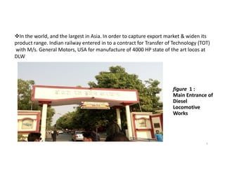
The Diesel Locomotive Works (DLW) in Varanasi, India , is a production unit owned
by Indian Railways, that manufactures diesel-electric locomotives and its spare parts.
It is the largest diesel-electric locomotive manufacturer in India. It is located on DLW
to BHU road of the metropolitan city of Varanasi.
Diesel Locomotive works was set up in 1961 with technical collaboration from M/s.
3
Diesel Locomotive works was set up in 1961 with technical collaboration from M/s.
ALCO/USA with a modest beginning of manufacturing 4 locos 1964, today DLW is the
largest Diesel Locomotive manufacturer.
Founded in 1961, the DLW rolled out its first locomotive three years later, on 3
January 1964. It manufactures locomotives which are variants based on the
original ALCO designs dating to 1960s and the GM EMD designs of the 1990s.
4. DLW has an annual production capacity of 250 locomotives and plans to increase it
to 275 based on the current demand.Since inception, DLW has produced total 8099
locomotives (up to 31st January, 2018) of various types.
DLW now manufactures “More than one locomotive a day”. DLW manufactured 334
diesel-electric locomotives in last financial year 2016-17, which is the highest ever loco
production by any loco manufacturing unit in India .
Diesel Locomotive Works is an ISO 9002 certified manufacturer of diesel electricDiesel Locomotive Works is an ISO 9002 certified manufacturer of diesel electric
locomotive and is one of the biggest industrial complexes in eastern part of the
country.
After assimilation of this technology, DLW will become the only factory in the world
capable of producing ALCO as well as General Motors designs of locomotives. DLW is
only manufacture of diesel –electric locomotive with both ALCO and GENERAL
MOTORS.
4
5. figure 1 :
In the world, and the largest in Asia. In order to capture export market & widen its
product range. Indian railway entered in to a contract for Transfer of Technology (TOT)
with M/s. General Motors, USA for manufacture of 4000 HP state of the art locos at
DLW
figure 1 :
Main Entrance of
Diesel
Locomotive
Works
5
6. 2. Maintenance Service Shop
The technical meaning of maintenance involves functional checks, servicing, repairing or
replacing of necessary devices, equipment, machinery, building infrastructure, and
supporting utilities in industrial, business, governmental, and residential installations.
Over time, this has come to often include both scheduled and preventive maintenance
as cost-effective practices to keep equipment ready for operation at the utilization stage
of a system lifecycle.
6
of a system lifecycle.
2.1 Classification of Maintains service shop:-
There are five types of maintains service
shop, these are following below-
1. Winding Shop 2. Electronics Lab
3. Meter 4. Battery Shop
5. Over Hydraulic Shop
7. 2.11 Winding Shop:-
An ideal step motor would have zero mechanical friction, its torque
would be proportional to ampere-turns and its only electrical characteristic would be
inductance. Ampere-turns simply mean that torque is proportional to the number of turns
of wire in the motor’s stator multiplied by the current passing through those turns of wire.
Anytime there are turns of wire surrounding a magnetic material such as the iron in the
motor’s stator, it will have an electrical property called inductance. Inductance describes
the energy stored in a magnetic field anytime current passes through this coil of wire.
7
Fig.2.11
Internal part of 3-phase motor
8. 2.12 Electronic Lab:-
There is a full-fledged Electronic Lab to cater to maintenance need of highly
sophisticated CNC machines and component / subassembly level trouble shooting of PCBs, Servo
Drives, and Microprocessor based controllers and electronic units. This Lab also supports other Zonal
Railways in repair of PCBs.
8
Fig 2.12 A view of Electronic lab in DLW
9. 2.13 Battery Shop:-
An electric battery is a device consisting of two or more electrochemical cells
that convert stored chemical energy into electrical energy. Each cell has a positive terminal, or
cathode, and a negative terminal, or anode. The terminal marked positive is at a higher electrical
potential energy than is the terminal marked negative. When a battery is connected to an
external circuit , Electrolytes are able to move as ions within, allowing the chemical reactions to
be completed at the separate terminals and so deliver energy to the external circuit. It is the
movement of those ions within the battery which allows current to flow out of the battery to
perform work.
9
perform work.
Chemical action during discharge
Pbo2 + H2 + H2SO4= PBSO4 + 2H2O ( at + Ve )------ (i)
Pb + SO4 = PbSO4 (at – Ve ) --------------- (ii)
Chemical action during charging
PbSO4 + H2 = Pb + H2SO4(at – Ve )------------- (iii)
PbSO4 + SO4 + 2H2O = PbO2 +2H2O ( at + Ve )------- (iv)
10. 2.14 Meter Shop:-
Meter (in locomotive) is a device that measures the amount of loco speed,
air pressure ,Fuel, diesel pressure, power of electricity and meter-calibration etc.
10
Fig 2.14 A view of Meter shop in DLW
11. 2.15 Over hydraulic Shop:-
Hydraulics is a technology and applied science using engineering
, chemistry, and other sciences involving the mechanical properties and use of liquids.
At a very basic level, hydraulics is the liquid counterpart of pneumatics, which
concerns gases. Fluid mechanics provides the theoretical foundation for hydraulics,
which focuses on the applied engineering using the properties of fluids. In its fluid
power applications, hydraulics is used for the generation, control, and transmission
11
power applications, hydraulics is used for the generation, control, and transmission
of power by the use of pressurized liquids. Hydraulic topics range through some parts
of science and most of engineering modules, and cover concepts such as pipe flow
dam design, fluidics and fluid control circuitry. The principles of hydraulics are in use
naturally in the human body within the vascular system and erectile tissue.
12. 3. Central Transport Shop
Introduction:-
Meaning of the transport is movement of any things. But in workshops, it
can be defined as movement of machines or materials from one place to another place
for utilization called transport. The vehicle by which these are transported called
transportation. In workshops Fort Lift Truck are used for transport. In this workshop we
use Mini Crane or Crane for movement of light and heavy part of machine.use Mini Crane or Crane for movement of light and heavy part of machine.
On the
process of working if the any part of transportation vehicle getting damage, such as
motor does not working properly . After several testing resolve the problem which
occurs in motor.
In central transport shop electrical department works is maintenance
of motor. If the motor getting damage and not to be operate again then it can be
replaced by new motor. The efficiency of new motor is better than previous motor.
13. 3.1 Useful Machines for transport:-
There are several equipments are used for transport.
3.1.1 Fork Lift Truck:-
A forklift (also called lift truck, jitney, fork truck, fork hoist, and forklift
truck) is a powered industrial truck used to lift and move materials over short distances. The
forklift was developed in the early 20th century by various companies, including Clark.
General operation:-
Forklifts are rated for loads at a
13
Forklifts are rated for loads at a
specified maximum weight and a specified forward
center of gravity. It can be lifted the load upto 5000
pound safely.
Fig3.1.1 A View of Fork Lift Truck
14. 3.3.2 Mini Crane:-
A crane is a type of machine, generally equipped with a hoist
rope, wire ropes or chains, and sheaves, that can be used both to lift and lower
materials and to move them horizontally. It is mainly used for lifting heavy things and
transporting them to other places. The device uses one or more simple machines to
create mechanical advantage and thus move loads beyond the normal capability of a
human
14
Fig3.2.2 A view of mini crane
In crane, maintenance of moving parts are
include in electrical department.
16. 4. SCADA
Introduction:-
Supervisory control and data acquisition (SCADA) is a control system architecture
that uses computers, networked data communications and graphical user interfaces for high-level
process supervisory management, but uses other peripheral devices such as programmable logic
controller (PLC) and discrete PID controllers to interface with the process plant or machinery. The
operator interfaces that enable monitoring and the issuing of process commands, such asoperator interfaces that enable monitoring and the issuing of process commands, such as
controller set point changes, are handled through the SCADA computer system.
However, the real-
time control logic or controller calculations are performed by networked modules that connect to
the field sensors and actuators.
large SCADA systems have grown to become very similar
to distributed control systems in function, but using multiple means of interfacing with the plant.
They can control large-scale processes that can include multiple sites, and work over large
distances as well as small distance.
17. 4.1 Component of SCADA system:-
There are following components of SCADA system-
1. Supervisory computers 2. Remote terminal units
3. Programmable logic controllers 4. Communication infrastructure
5. Human-machine interface
4.1.1 Supervisory computers:-
17
4.1.1 Supervisory computers:-
In smaller SCADA systems, the supervisory computer may be
composed of a single PC, in which case the HMI is a part of this computer. In larger SCADA
systems, the master station may include several HMIs hosted on client computers, multiple
servers for data acquisition, distributed software applications, and disaster recovery sites. To
increase the integrity of the system the multiple servers will often be configured in a dual-
redundant or hot-standby formation providing continuous control and monitoring in the
event of a server malfunction or breakdown.
18. 4.1.2 Remote terminal units:-
Remote terminal units, also known as (RTUs), connect to sensors
and actuators in the process, and are networked to the supervisory computer system. RTUs are
"intelligent I/O" and often have embedded control capabilities such as ladder logic in order to
accomplish bolean logic operations.
4.1.3 Programmable logic controllers:-
18
4.1.3 Programmable logic controllers:-
These are connected to sensors and actuators in
the process, and are networked to the supervisory system in the same way as RTUs. PLCs
have more sophisticated embedded control capabilities than RTUs, and are programmed in
one or more IEC 61131-3 programming languages. PLCs are often used in place of RTUs as
field devices because they are more economical, versatile, flexible and configurable.
19. 4.1.4 Communication infrastructure:-
This connects the supervisory computer system to the
RTUs and PLCs, and may use industry standard or manufacturer proprietary protocols. Both
RTU's and PLC's operate autonomously on the near-real time control of the process, using the
last command given from the supervisory system. Failure of the communications network
does not necessarily stop the plant process controls, and on resumption of communications,
the operator can continue with monitoring and control.
19
4.1.5 Human-machine interface:-
The human-machine interface (HMI) is the operator
window of the supervisory system. It presents plant information to the operating personnel
graphically in the form of mimic diagrams, which are a schematic representation of the plant
being controlled, and alarm and event logging pages.
20. 5 Colony
Introduction:-
Electrical transmission is the process of transferring electrical energy to the
Consumer. Electrical energy generated at high power facility and stepped up by using step up
transformer and then transmitted through the transmission line at high voltage . After
20
transformer and then transmitted through the transmission line at high voltage . After
transmitting at high voltage it stepped down by using step down transformer and then
distributed at low voltage. For heavy consumer 3-phase supply are produced but for light
consumer 1-phase supply are produced.
There is three main part of supply system
1. Generation
2. Primary and secondary transmission
3. Primary and secondary distribution
22. 5.1 Generating station:-
G.S. represents the generating station where electric power is
produced by 3-phase alternators operating in parallel. The usual generation voltage is 11 kV.
For economy in the transmission of electric power, the generation voltage (i.e., 11 kV) is stepped
upto 132 kV at the generating station with the help of 3-phase transformers.
5.2 Primary transmission:-
22
5.2 Primary transmission:-
The electric power at 132 kV is transmitted by 3-phase, 3-wire
overhead system to the outskirts of the city. This forms the primary transmission
5.3 Secondary Transmission:-
The primary transmission line terminates at the receiving station
(RS) which usually lies at the outskirts of the city. At the receiving station, the voltage is reduced
to 33kV by step-down transformers. From this station, electric power is transmitted at 33kV by
3-phase, 3-wire overhead system to various sub-stations (SS) located at the strategic points in
the city. This forms the secondary transmission.
23. 5.4 Primary distribution:-
The secondary transmission line terminates at the sub-station (SS)
where voltage is reduced from 33 kV to 11kV, 3-phase, 3-wire. The 11 kV lines run along the
important road sides of the city. This forms the primary distribution. It may be noted that big
consumers (having demand more than 50 kW) are generally supplied power at 11 kV for
further handling with their own sub-stations.
23
5.5 Secondary distribution:-
The electric power from primary distribution line (11 kV) is
delivered to distribution sub-stations (DS). These sub-stations are located near the
consumers’ localities and step down the voltage to 400 V, 3-phase, 4-wire for secondary
distribution. The voltage between any two phases is 400 V and between any phase and
neutral is 230 V.