Download to read offline
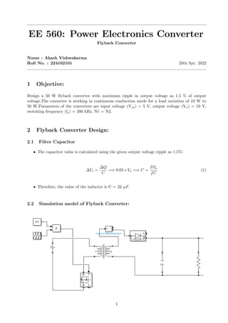
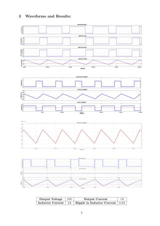

This document summarizes the design of a 50W flyback converter with an input voltage of 5V, output voltage of 10V, and switching frequency of 200kHz. The converter is designed to operate in continuous conduction mode for loads between 10W and 50W, with maximum output voltage ripple of 1.5% of the output voltage. The design calculations show that a 22uF capacitor is required to limit the output ripple to the specified level. Simulation waveforms confirm the output voltage is 10V with 1A current, while the inductor current is 2A with 0.3A ripple.


